 Skip to content
How Do You Choose the Right End Mill Geometry?A Practical Guide to Rake Angle, Helix Angle and Flute Design in Modern CNC Milling
Table of Contents
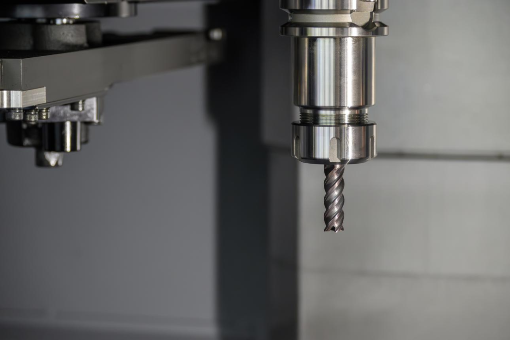
Why does one end mill cut smoothly for hours while another breaks only minutes after entering the workpiece? Why can two tools made from the same carbide grade behave completely differently under seemingly identical cutting conditions? For many machinists and purchasing engineers, the first instinct is often to look at the coating, the carbide substrate, or the machine itself. Yet in real machining applications, the answer is often much simpler—and much more fundamental. The real difference frequently lies in geometry.
End mill geometry determines how the cutter enters material, how chips leave the cutting zone, how heat is generated, and how vibration is transferred through the tool body. It influences spindle load, tool life, surface finish, dimensional accuracy, and even machining cost per part. A premium carbide grade can still fail if the geometry is wrong for the material being machined. On the other hand, a well-designed geometry often allows a tool to outperform expectations even under aggressive cutting conditions.
For this reason, understanding end mill geometry is not just useful for tool manufacturers. It matters equally to CNC programmers, operators, distributors, and buyers selecting tools for production.
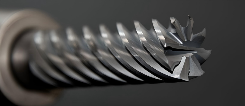
Why does end mill geometry matter so much in CNC milling?
In modern CNC machining, efficiency is no longer measured only by spindle speed or feed rate. Productivity depends on how effectively a tool converts rotation into controlled material removal. Geometry is the interface that makes this possible.
Every feature on an end mill—from flute shape to helix angle—changes the way cutting forces are distributed. It controls whether chips evacuate cleanly or pack inside the slot. It determines whether heat leaves with the chip or remains concentrated at the cutting edge. It affects whether the tool cuts quietly or begins vibrating under load.
This becomes even more important in today’s machining environments, where manufacturers are pushing harder materials, higher spindle speeds, deeper axial engagement, and tighter tolerance requirements. As cutting parameters increase, geometry becomes increasingly sensitive. Small design differences can create significant performance changes.
That is why modern carbide end mills are rarely designed as universal tools. Most are optimized for specific materials and machining strategies. Geometry is the reason a tool can feel “perfect” in aluminum yet unstable in stainless steel.
What role does rake angle play in cutting performance?
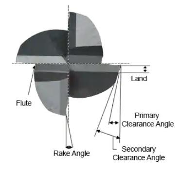
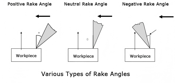
Among all geometric features, rake angle has perhaps the most immediate influence on cutting behavior. It controls how aggressively the edge enters the material and how the chip begins to form.
A larger positive rake angle creates a sharper cutting edge. The tool enters material more easily, requiring less cutting force. Chips shear faster and flow more freely along the flute. This reduces heat and usually improves surface finish. That is why end mills designed for aluminum often use highly positive rake geometry combined with polished flutes.
When machining softer and ductile materials such as aluminum, copper, or plastics, this sharper geometry helps prevent material from sticking to the cutting edge. It improves chip evacuation and reduces built-up edge formation.
However, sharpness is not always an advantage. In harder materials, too much rake angle weakens the edge. Under heavy load, the cutting edge becomes vulnerable to micro-chipping or premature failure. This is why tools for hardened steel or stainless steel generally use a smaller positive rake angle, trading some sharpness for strength and durability.
The best rake angle is always a compromise between cutting ease and edge stability. Tool designers constantly balance these two factors depending on application.
Why is helix angle often considered the heart of end mill design?
If rake angle determines how the tool cuts into material, helix angle largely determines how the tool behaves once cutting begins.
Helix angle influences chip evacuation, vibration control, axial force direction, and overall cutting smoothness. It is one of the most visible differences between end mills—and often one of the most misunderstood.
A lower helix angle generally creates a stronger edge and more rigid cutter body. It works well in hard materials or roughing applications where strength is more important than finish. A higher helix angle tends to cut more smoothly and evacuate chips more efficiently. It reduces radial cutting force and improves surface quality.
This is why high-helix carbide end mills are widely preferred for aluminum machining. Chips leave the cutting zone quickly, reducing recutting and heat buildup.
By contrast, steel machining often favors moderate helix geometry because it provides a more balanced combination of strength, chip control, and tool life.
Typical helix angle reference
Application | Common Helix Angle |
General steel milling | 30°–35° |
Stainless steel | 35°–40° |
Aluminum | 40°–45° |
High-speed finishing | 45°+ |
Anti-vibration milling | Variable helix |
Variable helix designs have become especially popular in recent years because they help suppress harmonic vibration and chatter, particularly in long-reach machining and high-speed side milling.

How does flute count affect machining results?
Flute count seems simple at first glance, but it has a direct impact on machining stability.
More flutes generally mean greater rigidity. Less flute space means a larger core diameter, which increases strength. This helps improve tool stability and often leads to better surface finish.
But there is always a trade-off.
As flute count increases, chip space becomes smaller. If chips cannot evacuate effectively, they remain trapped in the cutting zone. Recutting occurs. Heat rises. Tool wear accelerates rapidly.
This is why 2-flute and 3-flute end mills dominate aluminum machining. Their larger flute valleys allow chips to escape freely, especially during slotting.
Four-flute cutters are more common in steel because chip volume is smaller and rigidity becomes more important.
Six-flute tools are typically reserved for hardened steel finishing, where shallow radial cuts and high feed rates benefit from increased edge contact and rigidity.
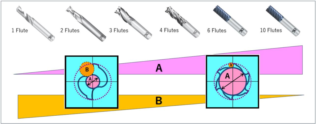
Common flute count comparison
Flute Count | Best Use | Main Benefit |
2 Flute | Aluminum slotting | Maximum chip evacuation |
3 Flute | Aluminum general milling | Balance of feed and chip space |
4 Flute | Steel milling | Rigidity + finish |
6 Flute | Hardened steel finishing | Stability + wear resistance |
There is no universally “better” flute count. The correct choice always depends on material, depth of cut, and machining strategy.
How should geometry change depending on the material?
This is where end mill selection becomes practical.
Different materials behave differently during cutting. Aluminum produces large soft chips and tends to weld. Stainless steel work-hardens and generates heat quickly. Hardened steel creates high edge pressure. Geometry must respond accordingly.
A tool designed for aluminum typically benefits from a high helix angle, polished flute surface, larger flute depth, and sharp positive rake. The goal is fast chip evacuation and reduced adhesion.
A steel-cutting end mill usually requires stronger edge support and balanced chip control. Moderate helix geometry with four flutes often performs best.
For hardened steel, rigidity becomes critical. A stronger core, reduced rake angle, and multi-flute design help protect the cutting edge while maintaining dimensional control.
Material-based geometry selection guide
Material | Recommended Geometry |
Aluminum | 2–3 flute / 45° helix / polished flute |
Carbon steel | 4 flute / 35° helix |
Stainless steel | 4–5 flute / variable helix |
Hardened steel | 4–6 flute / reinforced core |
Titanium | variable helix / heat-resistant geometry |
So what geometry should you choose?
The most effective end mill geometry is never chosen by one parameter alone. Rake angle, relief angle, helix angle, flute depth, and flute count all work together as a system.
The right selection depends on the material being machined, machine rigidity, cutting strategy, spindle capability, coolant condition, and whether the operation is roughing or finishing.
That is why experienced machinists rarely ask only “What diameter end mill do I need?”
Instead, they ask deeper questions.
How will chips evacuate?
Where will heat go?
How rigid is the setup?
What cutting forces will be generated?
How much vibration can the tool tolerate?
Those questions lead to the right geometry.
And geometry leads to performance.

Final thoughts
Choosing an end mill is never only about diameter or coating. Geometry is what transforms carbide into a cutting solution.
When geometry matches the application, the tool cuts cleaner, lasts longer, and performs more predictably. Chips evacuate smoothly, surface finish improves, spindle load decreases, and machining becomes more stable.
In many cases, improving tool performance does not begin by changing speeds and feeds.
It begins by choosing the correct cutting edge geometry from the start.
For manufacturers looking to improve CNC milling performance, geometry is not a detail.
It is the design language of the tool itself.





