
Why Deep Hole Drilling Still Fails Even with High-Pressure Coolant — A Practical Guide to Chip Control and Stability
Table of Contents
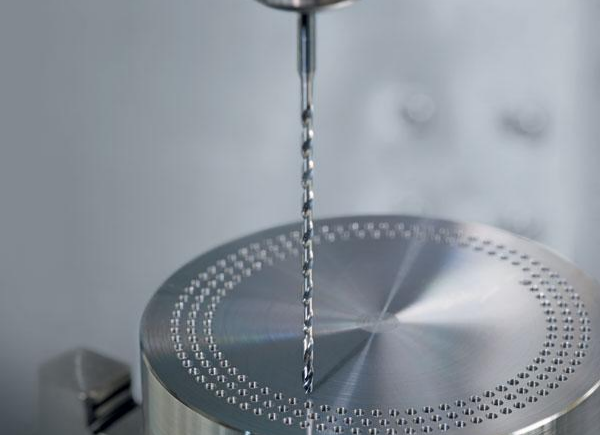
Deep hole drilling, typically defined as a length-to-diameter ratio (L/D) greater than 10, is often described as a “routine” machining process. In reality, it is anything but routine. It represents one of the most complex interactions between tool geometry, chip formation, coolant behavior, and machine stability. Many manufacturers believe that upgrading to high-pressure coolant systems will automatically solve their chip evacuation problems. Yet, in real production environments—especially in industries such as hydraulic systems, mold ejectors, and aerospace fasteners—failures persist even with coolant pressures exceeding 30 bar or more.
So why does deep hole drilling still fail under seemingly ideal conditions? The answer lies in a common but critical misunderstanding: chip evacuation is not controlled by coolant pressure alone. Instead, it is the result of a dynamic balance between chip formation, tool design, and cutting parameters. When this balance is broken, no amount of pressure can compensate for it.

When High-Pressure Coolant Becomes a Problem Instead of a Solution
High-pressure coolant (HPC) has become a standard feature in modern deep hole drilling, especially for carbide drills with internal coolant channels. Its primary role is to assist chip evacuation and reduce heat concentration at the cutting edge. However, what is often overlooked is that coolant pressure must work in harmony with the chipbreaker geometry of the tool. When this relationship is ignored, increasing pressure can actually degrade machining performance.
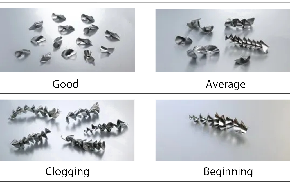
In practical testing on stainless steel 304 with a Ø12 mm carbide deep hole drill at L/D 15, a clear pattern emerges. As coolant pressure increases from 20 bar to 50 bar, chip morphology improves significantly, transitioning from long, tangled chips to stable C-shaped chips that evacuate smoothly. This is the ideal condition for deep hole drilling. However, when pressure is further increased to around 80 bar, the behavior changes again—but not for the better. Instead of forming controlled chips, the material is fragmented into micro-sized or fan-shaped debris. These smaller particles do not flow efficiently through the flute. Instead, they accumulate between the tool flank and the hole wall, increasing friction and accelerating wear.
The result is counterintuitive: higher pressure leads to worse surface finish and reduced tool life. Surface roughness can double, and tool failure becomes more frequent. This phenomenon highlights an important principle: there is always an optimal pressure window, and exceeding it introduces instability rather than improving performance.
Effect of Coolant Pressure on Chip Formation and Surface Quality
Coolant Pressure | Chip Morphology | Stability | Surface Roughness |
20 bar | Long string chips | Poor | Ra 2.5 μm |
50 bar | Uniform C-shaped chips | Stable | Ra 1.6 μm |
80 bar | Powder / fragmented | Unstable | Ra 3.2 μm |
This is why modern carbide deep hole drills—especially those designed for internal cooling—must be selected together with a suitable pressure range. Tools with larger flute volume and optimized chipbreaker geometry, such as those developed for high-efficiency drilling, can tolerate higher pressures. In contrast, tools with limited chip space require more controlled coolant delivery to avoid premature chip fragmentation.
Why Traditional Cutting Parameters No Longer Work in Deep Hole Drilling
If coolant pressure is only part of the story, then cutting parameters are the other half—and often the more decisive one. Many machinists still apply a conventional strategy of high spindle speed combined with low feed rate, assuming this reduces cutting force and improves tool life. In shallow drilling, this may work. In deep hole drilling, it often leads directly to failure.
The fundamental issue is chip thickness. When the feed rate is too low, the chip becomes thin and lacks the rigidity needed to curl properly. Instead of forming compact, controlled shapes, it turns into long, stringy chips that tangle inside the flute. These chips are extremely difficult to evacuate, especially in deep holes where space is limited. On the other hand, increasing the feed rate within a reasonable range increases chip thickness, allowing the chipbreaker to function effectively and produce short, stable chips.
However, feed rate cannot be increased indefinitely. When it becomes too high, cutting forces rise sharply, and the long, slender structure of a deep hole drill begins to deflect. This introduces vibration, which further disrupts chip formation and reduces tool life. Similarly, excessive spindle speed increases centrifugal force, amplifying tool deflection and causing unstable cutting conditions.
Relationship Between Feed Rate and Chip Behavior
Feed Rate (mm/rev) | Chip Condition | Machining Result |
< 0.05 | Thin, stringy chips | Chip clogging |
0.08–0.15 | Stable C-shaped | Optimal performance |
> 0.25 | Thick, aggressive | Vibration risk |
The optimal cutting zone for deep hole drilling is therefore not at the extremes, but in a balanced region: moderate cutting speed combined with medium-to-high feed rate. In most steel applications, a cutting speed of 50–80 m/min and a feed rate of 0.08–0.15 mm/rev provide stable performance.
An even more advanced approach is to maintain constant chip thickness throughout the drilling process. As the depth increases and tool rigidity decreases, the spindle speed can be slightly reduced while keeping the feed rate constant. This maintains consistent cutting conditions and prevents the gradual deterioration of chip formation.
Tool Rigidity: The Invisible Limitation You Can’t Ignore
Even with perfect coolant and cutting parameters, deep hole drilling can fail if tool rigidity is insufficient. This becomes especially critical when the length-to-diameter ratio exceeds 20. At this point, the tool behaves less like a rigid cutting instrument and more like a flexible structure subject to dynamic forces.
Solid carbide deep hole drills offer excellent stiffness due to their high elastic modulus, making them suitable for L/D ratios up to around 15. Beyond this range, however, their natural frequency decreases, increasing the risk of resonance with the cutting process. This resonance manifests as chatter, poor surface finish, and accelerated tool wear.
To address this, many advanced machining setups use heavy metal anti-vibration tool holders, often made from tungsten alloys. These tools incorporate internal damping mechanisms that absorb vibration energy and significantly improve dynamic stability. In deep hole drilling applications with L/D ratios between 20 and 30, such systems can increase stability by two to three times compared to standard carbide tools.
Tool Selection Based on L/D Ratio
L/D Ratio | Recommended Tool Type |
≤ 15 | Solid carbide deep hole drill |
15–25 | Anti-vibration holder + carbide drill |
> 25 | Step drilling / staged machining |
Proper clamping is equally important. A minimum clamping length of four times the tool diameter is recommended to ensure stability and minimize micro-movement at the interface. Without this, even the best tool design cannot perform effectively.
Why Material-Specific Strategies Are Essential
One of the most overlooked aspects of deep hole drilling is the variation in chip behavior across different materials. Applying the same parameters to stainless steel, aluminum, and superalloys is a guaranteed way to encounter problems.
Low carbon steels, for example, tend to produce continuous chips due to their ductility. In this case, higher cutting speeds combined with larger feed rates help promote thermal softening and chip breakage. Aluminum alloys present a different challenge: their tendency to adhere to the cutting edge. Here, lubrication becomes more important than pressure, and polished carbide or PCD tools are often necessary to reduce friction. Superalloys such as Inconel 718 introduce yet another complexity, with strong work hardening effects that demand a minimum chip thickness to avoid rubbing and edge chipping.
Understanding these differences is essential for selecting the right carbide deep hole drill and optimizing its performance in real production environments.
What Defines a High-Performance Deep Hole Drill?
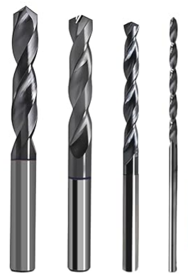
A high-performance deep hole drill is not defined by coating alone. Instead, it is the result of a carefully engineered combination of features designed to control chip formation and maintain stability under extreme conditions. These include optimized chipbreaker geometry to ensure consistent chip curling, large flute volume to facilitate evacuation, and internal coolant channels that deliver coolant precisely to the cutting zone.
In our experience, tools such as HNCarbide deep hole drills are designed with these principles in mind. Their geometry supports stable chip formation within the critical pressure window, while their internal coolant system ensures efficient heat removal without over-fragmenting chips. Combined with high-precision grinding and advanced coatings, these tools are capable of maintaining consistent performance even in demanding applications such as stainless steel and alloy steel deep hole drilling.

Conclusion: Deep Hole Drilling Is a System, Not a Single Variable
Deep hole drilling cannot be optimized by adjusting a single parameter. Increasing coolant pressure without considering chip formation, or reducing feed rate without understanding its effect on chip thickness, often leads to worse results rather than improvements.
The key to success lies in treating the process as an integrated system. Chip morphology, cutting force, vibration, and coolant behavior must all be aligned. By monitoring chip shape, machine load, and cutting sound, engineers can build a feedback loop that allows continuous optimization.
Ultimately, the goal is simple: achieve stable chip formation and reliable evacuation. Once this is accomplished, improvements in tool life, surface quality, and productivity naturally follow.


