 Skip to content
Types of Taps: How to Choose for Blind Holes, Through Holes and Difficult Materials
Table of Contents
A broken tap in a nearly finished part costs more than the tool itself. The operator must recover it, inspect the thread and often scrap a component that has already passed through several operations. The first selection question is therefore simple: where will the chips go? Hole type and workpiece material answer much of that question before substrate or coating enters the discussion.
The four families below cover most shop-floor choices. Their names describe how they cut or form the thread, but each family still has variations in chamfer, thread tolerance, flute geometry and surface treatment. Check the supplier’s application data for the exact tool rather than treating a family name as a complete specification.
Start with chip direction
Tap family | What happens to chips | Best starting point | Main limitation |
Straight-flute cutting tap | Chips remain in the flutes or are flushed away | Hand tapping, repair, cast iron and other short-chip materials | Limited control of long, stringy chips |
Right-hand spiral-flute cutting tap | Flutes draw chips toward the hole entrance | Blind holes in ductile materials | Reduced core strength as flute volume increases |
Spiral-point cutting tap | Point pushes chips ahead of the tap | Through holes in steels and other chip-forming alloys | Needs a clear exit and room for chips beyond the thread |
Form or roll tap | Produces no cutting chips | Ductile materials when chip control is critical | Requires a different pilot-hole size and higher torque |
Straight-flute taps: simple, but chip control is limited
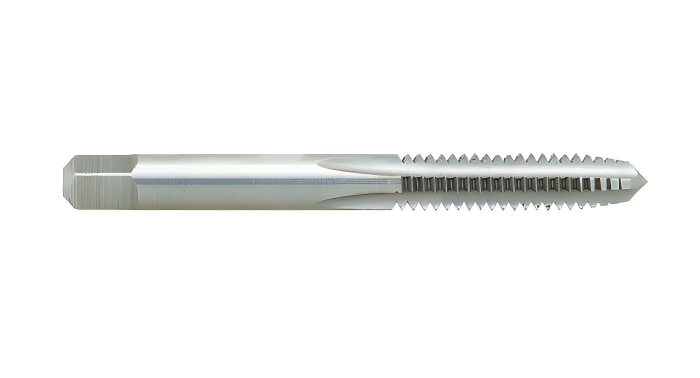
The flutes run parallel to the tap axis. This makes straight-flute taps straightforward to manufacture and regrind, and their relatively substantial core can be useful where rigidity matters. They are familiar in hand-tap sets and repair work. Machine versions can work well in cast iron, free-machining brass and other materials that produce small, broken chips.
The geometry does not actively lift or push long chips. In a blind hole in low-carbon steel or stainless steel, those chips can pack near the bottom or drag against finished thread flanks as the tap reverses. Coolant delivery, hole depth and chamfer length matter. A straight-flute tap can cut either hole type in a suitable application; it is not a universal first choice for every material simply because it fits both.
Spiral-flute taps: pull chips out of blind holes
A conventional right-hand spiral-flute tap for a right-hand thread carries chips back toward the hole entrance. That is why this style is commonly specified for blind-hole production in steel, aluminum and stainless steel. It is particularly useful when the thread must approach the bottom without a large chip pocket.
More helix generally improves chip lifting, but removes material from the tap core. The suitable angle depends on alloy, chip shape, diameter, depth and the manufacturer’s geometry. A figure such as 35° or 45° is a product feature, not a safe universal rule. A spiral-flute tap may also be used in some through-hole applications; it is simply often less efficient there than a spiral-point design that sends chips through the exit.
Spiral-point taps: send chips through the exit
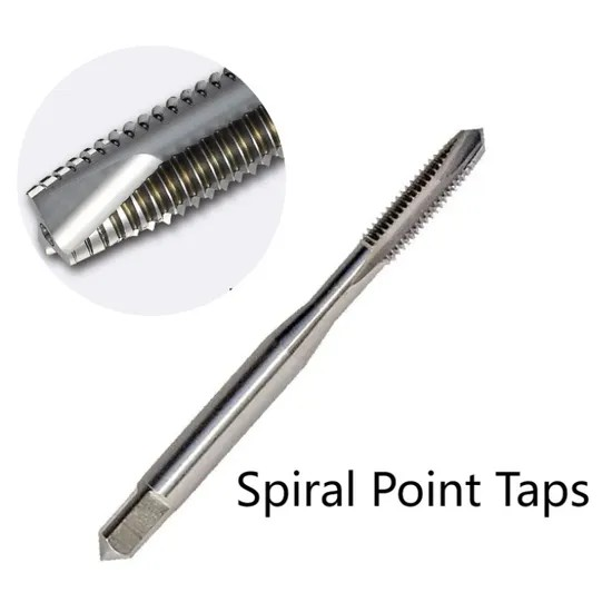
Also called gun taps, spiral-point taps usually have straight main flutes and an angled cutting point. The point drives chips forward, away from the newly cut thread. With a clear exit, this gives reliable chip flow, a strong core and productive through-hole tapping in many steels and stainless grades.
Do not use the ordinary spiral-point choice in a blind hole: the chips have nowhere to go and can compact under the chamfer. Confirm that the drill breaks through completely and that there is sufficient clearance beneath the workpiece. In fixture plates or stacked parts, a nominally through hole can behave like a blind hole if the exit is blocked.
Form taps: no chips, but a different process
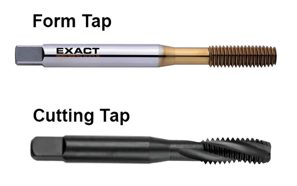
A form tap displaces metal instead of cutting it. Its lobed profile presses the pilot-hole wall into the thread shape, so chip evacuation disappears from the problem. That is attractive for blind holes, deep small threads and automated lines where a stray chip can stop assembly. Formed threads can have a smooth surface and favorable strength in suitable materials, though the outcome depends on the alloy and process rather than on the tap alone.
The tradeoff is higher torque and a much tighter dependence on pilot-hole diameter. The pilot hole is larger than the one used for a cutting tap of the same nominal thread, but its exact size must come from the tap maker’s chart for the material and desired thread percentage. Too small a hole can overload the tap or raise the thread crest; too large a hole produces an incomplete thread. Use a lubricant suitable for forming, especially in stainless steel.
Aluminum, copper alloys and many low-carbon steels are common candidates. Some austenitic and duplex stainless grades can also be formed with a purpose-designed tap, sufficient torque and controlled lubrication. Cast iron and other brittle materials are poor candidates because they cannot flow plastically in the required way. Qualification trials are especially important in work-hardening alloys.
Match the tap to the material and hole
Workpiece and hole | Practical starting choice | What to confirm in a trial |
Cast iron, through or blind | Straight-flute cutting tap, often with geometry for abrasive short chips | Dust removal, wear and thread gauge results |
Carbon or low-alloy steel, through | Spiral-point tap | Exit clearance, chip shape and thread size |
Carbon or low-alloy steel, blind | Right-hand spiral-flute tap | Chip lifting, bottom clearance and reversal |
Aluminum, blind | Polished spiral-flute cutter or form tap if the alloy is sufficiently ductile | Built-up edge, lubrication and pilot-hole control |
Austenitic stainless, through | Application-specific spiral-point tap | Work hardening, lubrication, torque and tap life |
Austenitic stainless, blind | Application-specific spiral-flute tap; form tap only after qualification | Chip packing or forming torque, thread quality |
Duplex stainless, including 2205 | Purpose-designed PM-HSS cutting tap; assess forming only with supplier support | Torque, work hardening, coolant and repeatability |
This table is a starting point, not a substitute for a tapping trial. Thread size, depth-to-diameter ratio, fixturing and machine synchronization may change the answer. A blind M3 thread and a shallow M20 thread have very different breakage risks even in the same alloy.
Substrate and coating come after geometry
Conventional HSS is economical for moderate duty. Cobalt-bearing HSS-E and powder-metallurgy HSS offer more heat resistance or a useful toughness–wear balance for demanding steels, depending on grade and heat treatment. PM-HSS can support refined cutting edges and consistent performance in stainless or titanium applications, but an advertised life multiplier from one test should not be applied to every shop. Solid-carbide taps can work in stable, high-volume applications, including certain cast irons; their lower tolerance for impact and misalignment makes them a specialized choice rather than an automatic upgrade.
Coatings also need an application match. TiN and TiCN are familiar wear-resistant options for many steels. TiAlN, AlCrN and other coatings appear on taps designed for difficult alloys, but the coating name alone does not establish suitability for duplex 2205. Edge preparation, flute geometry, substrate and lubrication have to work together. A coated tap that welds chips to the edge or runs beyond the machine’s torque capacity will still fail.
For purchasing, request the manufacturer’s workpiece-group recommendation, pilot-drill chart, thread tolerance, chamfer style, maximum depth and coolant guidance. Ask for trial results in the actual alloy rather than accepting a generic “stainless steel” label. Duplex 2205, for example, should be specified by grade and condition because its behavior differs from free-machining austenitic stainless.
A short troubleshooting check before changing taps
Symptom | Likely process issue | First check |
Chips packed at a blind-hole bottom | Chip flow points down, or clearance is inadequate | Tap family, usable depth and drill depth |
Scratched or torn thread flanks | Chips rub on reversal or material adheres to the edge | Chip evacuation, lubricant and edge condition |
High or rising torque | Pilot hole too small, edge wear or poor lubrication | Measure hole size and inspect the tap |
Intermittent breakage | Misalignment, blocked through-hole exit or unstable reversal | Holder, runout, synchronization and fixture clearance |
Formed thread fails gauging | Incorrect forming pilot hole or material variation | Supplier chart, hole measurement and thread percentage |
Before changing to a harder substrate or more expensive coating, measure the drilled hole and inspect the chips. A correct tap cannot compensate for a pilot hole that is undersized, a blocked exit or inadequate coolant.

Choose the process, then the product
For a ductile material in a blind hole, start with a chip-lifting spiral-flute tap; evaluate a form tap when chip-free production and the alloy’s formability justify the higher torque. For a clear through hole, start with a spiral-point tap. Use straight flutes where chips break readily or the job calls for hand tapping and repair. Then specify substrate, coating, chamfer and tolerance for the actual alloy and machine.
HNCarbide can help review thread geometry, material grade and production conditions when a standard tap selection is giving inconsistent results. Send the drawing and application details so the recommendation can be checked against the real hole, rather than a generic material label.





