 Skip to content
Twist Drill Anatomy Explained: How Geometry Controls Hole Quality, Tool Life, and Drilling Efficiency
Table of Contents
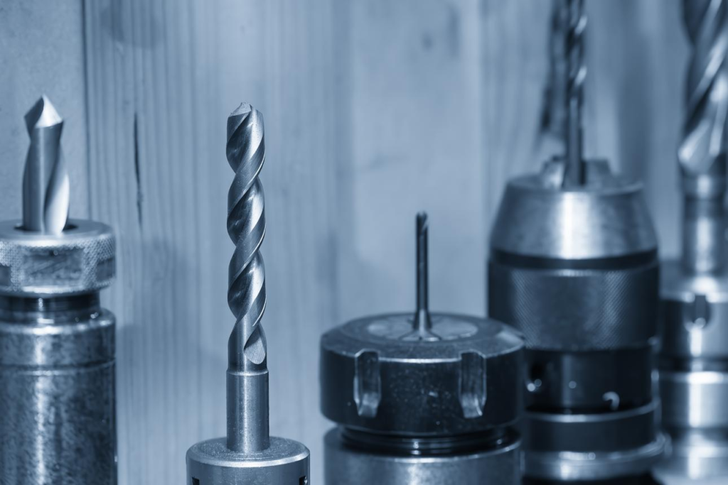
A twist drill may appear to be one of the simplest cutting tools in a machine shop, but in reality it is a highly engineered product. Every edge, surface, angle, and relief area affects how the tool enters material, forms chips, dissipates heat, maintains hole size, and resists wear over time. When users experience poor hole finish, oversize diameters, broken drills, or unstable cutting, the problem is often not the machine itself—it starts with the drill geometry.
For manufacturers, maintenance workshops, CNC machining centers, and metal fabrication companies, understanding drill anatomy is more than technical theory. It directly impacts productivity and cost per hole. A correctly designed drill can increase tool life dramatically, reduce cycle times, and improve consistency across thousands of parts.
At HNCarbide, we supply precision drilling tools for steel, stainless steel, cast iron, aluminum, and non-ferrous materials. In this guide, we explain how a standard twist drill is constructed, why each structural feature matters, and how professional users can choose better tools for modern machining.
Why Does Drill Geometry Matter So Much?
Many buyers compare drills only by price, coating color, or material grade. However, geometry is often the real difference between a low-cost tool and a high-performance one. Two drills made from similar raw material can perform completely differently if their point design, flute shape, margin accuracy, and web thickness are not the same.
During drilling, the tool must cut at the outer diameter while simultaneously pushing material aside at the center. It must evacuate chips upward through narrow flutes while rotating under load. It must remain straight inside the hole while resisting vibration and heat. That is a complex mechanical task for a tool that many people consider “basic.”
This is why industrial drilling tools from premium manufacturers focus heavily on geometry optimization. It is also why end users should understand how a twist drill works before choosing products for production use.
What Are the Main Sections of a Standard Twist Drill?
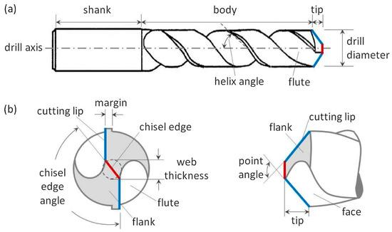
A standard Twist Drill Bit is generally divided into three functional sections: the cutting part, the guiding part, and the shank. The shank is used for clamping, while the cutting and guiding sections determine actual machining performance.
The cutting part is located at the point of the drill and performs material removal. This area includes the lips, chisel edge, rake surfaces, and flank surfaces. It is responsible for penetration, chip formation, cutting pressure, and hole entry quality.
Behind the point is the guiding section. Once the drill enters the hole, this area stabilizes movement, maintains diameter, supports chip evacuation, and reduces friction between tool and workpiece.
When these two zones are designed correctly, drilling becomes faster, smoother, and more predictable.
How Is the Cutting Part Constructed?
The cutting part of a standard twist drill consists of four key features: the rake face, flank face, main cutting edges, and chisel edge. Although these terms are technical, their roles are easy to understand once connected to real machining behavior.
The rake face is the surface over which chips flow immediately after material is cut. Its smoothness and angle affect chip control and cutting resistance. In sticky materials such as aluminum or austenitic stainless steel, polished rake faces can significantly reduce built-up edge and chip adhesion.
The flank face sits behind the cutting lip and faces the newly machined hole wall. This area provides clearance so the drill can cut rather than rub. If clearance is insufficient, friction rises quickly and heat builds at the cutting edge. If excessive, edge strength is weakened.
The main cutting edges, often called lips, are the primary cutting lines extending from the center toward the outer diameter. Most of the actual material removal occurs here. Lip symmetry is critical. Unequal lips often lead to oversized holes, vibration, poor surface finish, and shortened tool life.
At the center is the chisel edge, an area that does not cut efficiently like the lips. Instead, it pushes material aside under high pressure. Because spindle speed approaches zero at the centerline, this region tends to generate high thrust force and heat.
Why Is the Chisel Edge Often the Hidden Problem?
Many drilling issues begin at the center of the drill point. Since rotational speed at the center is minimal, the chisel edge behaves more like an extrusion wedge than a true cutting edge. This increases thrust load, makes entry less stable, and raises the risk of walking on hard surfaces.
That is why modern drills often use split-point grinding or web thinning. These designs shorten the chisel edge and improve self-centering behavior. They also reduce axial force, which helps smaller machines and handheld equipment drill more easily.
For users drilling stainless steel, alloy steel, or high-volume production parts, point thinning is one of the most valuable upgrades available. It improves both operator experience and tool life.
Drill Point Style | Entry Stability | Thrust Force | Best Use |
Standard 118° Point | Moderate | Higher | General-purpose drilling |
135° Split Point | High | Lower | CNC, stainless steel |
Web-Thinned Point | High | Lower | Harder materials, production use |
How Does the Guiding Part Improve Hole Accuracy?
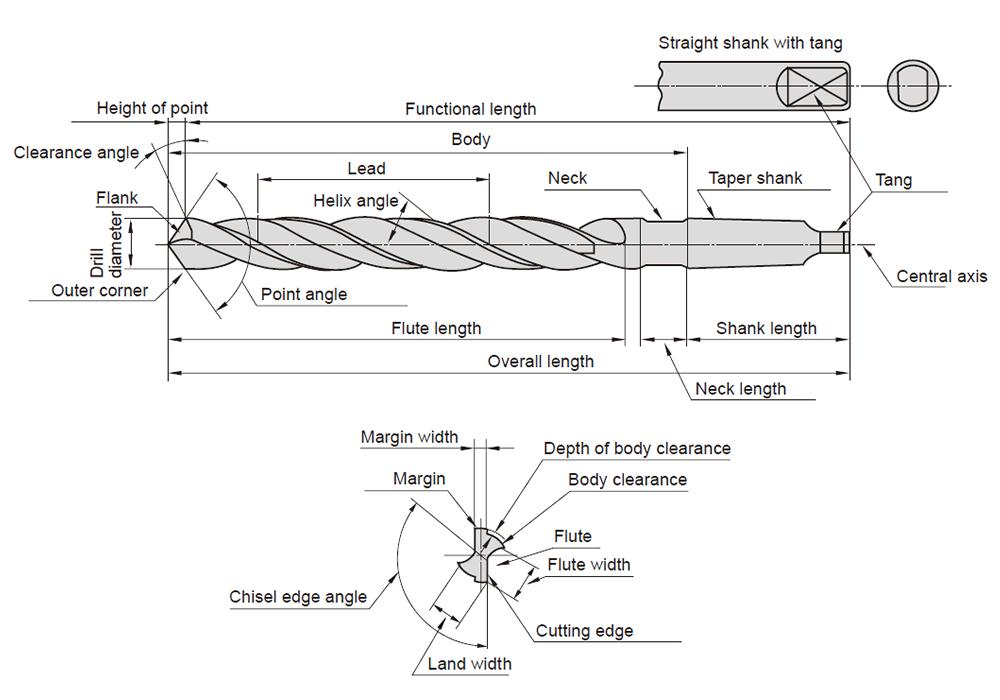
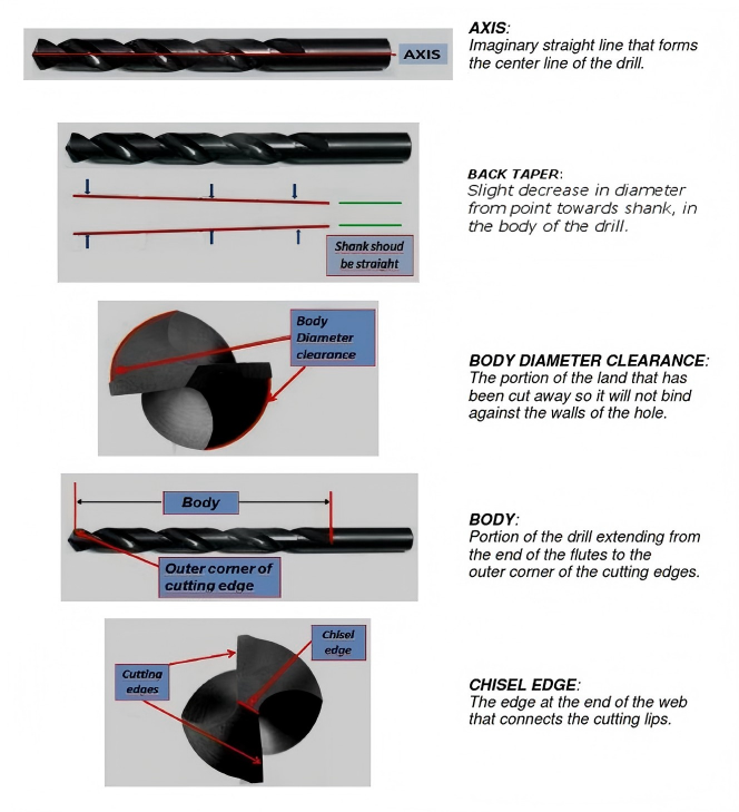
Once the drill enters the workpiece, the guiding section becomes extremely important. This portion includes the flutes, margins, body clearance, back taper, and web structure.
The flutes are the helical grooves running along the drill body. Most people recognize them visually, but their function goes far beyond appearance. Flutes create the rake geometry, provide a path for chip evacuation, allow coolant access, and influence core strength. A poorly designed flute can trap chips and create sudden breakage, especially in deeper holes.
Margins are the narrow raised lands along the outer diameter. These lightly contact the wall of the hole and guide the drill during rotation. Precision margins help maintain hole size and roundness. Low-quality margins often create oversize holes or rough surfaces.
Body clearance refers to the slight reduction in body diameter behind the margin. Without this relief, the drill would rub heavily against the hole wall, creating friction and heat.
Back taper is another subtle but important feature. Many quality drills are ground slightly smaller toward the shank. This minimizes drag in deep holes and improves straightness.
The web, or core, is the solid center material between the flutes. It provides strength and torque resistance. If too thin, the drill becomes fragile. If too thick, thrust force increases due to a wider chisel edge.
How Does Flute Geometry Affect Chip Evacuation?
Chip control is one of the biggest reasons drills fail. Even a sharp drill can break if chips are not evacuated properly. Flute geometry determines how efficiently chips leave the cutting zone.
For steel, a medium helix angle usually offers balanced performance. For aluminum, higher helix designs help remove long stringy chips quickly. For cast iron or brittle materials, lower helix angles can improve stability and control shorter chips.
This is why industrial buyers should never use one drill design for every material. Material-specific flute geometry can dramatically improve output and reduce downtime.
Helix Angle | Typical Material | Performance Characteristic |
15°–20° | Cast iron, brass | Stable, controlled chips |
25°–30° | Carbon steel | General-purpose balance |
35°–40° | Aluminum, stainless | Fast chip evacuation |
Why Do Some Drills Produce Oversized or Rough Holes?
Hole quality problems are often blamed on spindle runout or machine condition, but drill geometry frequently plays a major role.
If the two lips are unequal in length or angle, the drill cuts unevenly and enlarges the hole. If margins are inconsistent, the tool may wobble slightly inside the hole. If flute surfaces are rough, chips can scratch the wall during evacuation. If the point is worn, the drill may rub instead of cut.
In production environments where tolerances matter, geometry consistency from tool to tool is essential. This is one reason professional manufacturers inspect point symmetry, diameter tolerance, and flute grinding accuracy during production.
For users who repeatedly struggle with hole size variation, switching to precision-ground drills is often more effective than adjusting feeds and speeds endlessly.
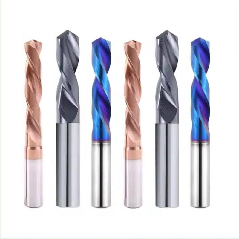
HSS or Solid Carbide: Which Twist Drill Is Better?
The answer depends on machine capability, material type, and production volume.
High Speed Steel Twist Drill Bit remains popular because it is economical, versatile, and easier to resharpen. It performs well in maintenance work, manual drilling, and lower-speed general fabrication.
Solid Carbide Twist Drill Bit is preferred in CNC machining and high-volume production because it offers higher hot hardness, better wear resistance, and greater rigidity. This allows faster cutting speeds and longer life, particularly in stainless steel, alloy steel, and abrasive materials.
If cost per hole matters more than initial purchase price, carbide is often the better long-term investment.
Drill Type | Initial Cost | Speed Capability | Tool Life | Best For |
HSS | Lower | Moderate | Moderate | Maintenance, hand drilling |
Cobalt HSS | Medium | Moderate | Better | Stainless steel |
Solid Carbide | Higher | High | Long | CNC production |
What Does HNCarbide Recommend for Modern Industrial Users?
For general steel fabrication, a DIN338 style HSS or cobalt drill with 118° or 135° point geometry remains a practical choice. It offers reliable performance with broad compatibility.
For stainless steel, we typically recommend split-point cobalt drills or solid carbide drills with polished flutes. Stainless generates heat quickly and tends to work harden, so sharp geometry and chip evacuation are essential.
For CNC production lines, internal coolant carbide drills in 3×D, 5×D, or deeper lengths are often the most efficient solution. These tools improve chip evacuation, reduce cycle time, and support stable unattended machining.
At HNCarbide, we also provide OEM solutions based on customer material type, machine platform, and target hole tolerance.
How Can You Choose the Right Twist Drill Faster?
Start by asking practical questions rather than comparing only price.
What material are you drilling? Is the hole through or blind? What depth ratio is required? Are you using a hand drill, drill press, or CNC machining center? How many holes per month will be produced? Is coolant available?
Once these answers are clear, selecting geometry becomes much easier. The wrong drill often costs more in downtime, scrap, and replacement than the right drill costs to buy.

Final Thoughts: A Better Drill Is Built Through Better Geometry
A twist drill is not just a sharpened cylinder of steel. It is a precision cutting system where every detail matters. The rake face influences chip flow. The lips determine cutting efficiency. The chisel edge controls thrust force. The margins guide the hole. The flute evacuates waste. The web provides strength.
When all of these elements are balanced, drilling becomes faster, cleaner, and more economical.
At HNCarbide, we focus on supplying twist drills designed for real industrial performance—not just catalog appearance. Whether you need HSS jobber drills, cobalt stainless drills, or carbide CNC drilling solutions, we help customers choose geometry that matches production reality.
If you are sourcing drills for steel, stainless steel, cast iron, or aluminum applications, contact HNCarbide today for technical recommendations and OEM support.


