Turning Chipbreaker Geometry and Chip Shapes: A Practical Guide to Chip Control
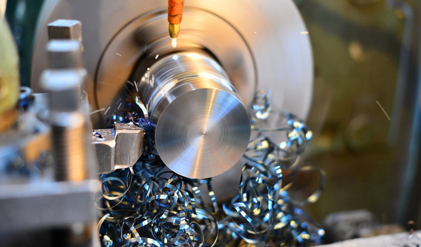
Long, stringy chips are more than a housekeeping problem. They can wrap around the chuck, drag across a finished diameter, damage an insert, block an automated cycle, or put an operator at risk. Yet a chipbreaker that snaps every chip into tiny fragments is not automatically the best choice either. Excessive chip impact can raise cutting-force variation and mark a finish pass.
Good chip control means producing a chip that is safe, predictable, and suitable for the operation. The right result depends on the interaction between chipbreaker geometry, workpiece material, feed, depth of cut, cutting speed, tool angles, and setup rigidity.
What a turning chipbreaker actually does
During turning, the material ahead of the cutting edge shears and flows across the rake face. A chipbreaker changes that flow path. Its groove, land, rake transitions, bumps, and pocket walls force the chip to bend. Once the bending strain is high enough, the chip breaks against the tool flank, the uncut workpiece surface, or its own previously formed coil.
Three outcomes matter on the shop floor:
- The chip must curl tightly enough to avoid becoming a continuous ribbon.
- Its flow direction must keep it away from the finished surface, toolholder, chuck, and operator.
- Breakage must occur without imposing more load than the cutting edge and setup can tolerate.
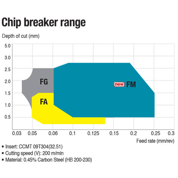
This is why chipbreaker selection charts use both feed per revolution and depth of cut. A groove that works well at 0.25 mm/rev and 2 mm depth of cut may not engage the chip at 0.06 mm/rev and 0.3 mm depth of cut. At the light condition, the chip may pass over the groove without enough contact or bending.
Classical chipbreaker groove cross-sections
Traditional carbide turning tools are often explained through three basic groove cross-sections. Modern indexable inserts use more complex three-dimensional forms, but the same mechanics still help when comparing finishing, medium, and roughing geometries.
Groove form | Geometry and chip action | Typical use and limitation |
Straight plus radius | A short straight rake section leads into a radiused groove. Narrower grooves and smaller radii create tighter curl and higher bending strain. | The most general classical form. A groove that is too narrow can pack chips, raise load, and chip the cutting edge. |
Full radius | The groove is formed mainly by a continuous arc, without a long straight rake section. It can maintain edge support while offering a smooth chip path. | Useful where a positive rake and free cutting action are needed, including ductile materials. The actual range still depends on feed and depth of cut. |
Conical pocket | A localized depression near the nose redirects and curls a relatively narrow chip. | Can help at light finishing depths, but may increase force concentration. It is a poor choice when a slender workpiece is already prone to deflection. |
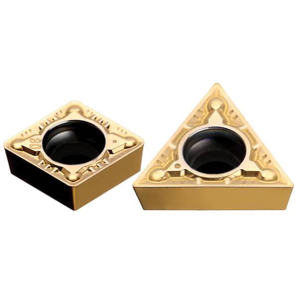
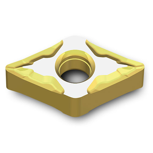
On a pressed carbide insert, these concepts are combined with edge lands, local rake changes, chip-control bumps, and different geometry around the nose and straight cutting edge. The molded top face is therefore better treated as a three-dimensional flow surface than as one simple groove.
Groove orientation and chip-flow direction
Classical turning-tool terminology also describes the angle between the chipbreaker groove and the main cutting edge. Three arrangements are useful as mental models.
An outward-inclined groove is wider and deeper near the tool nose. It starts curling the chip early and tends to direct the chip toward the tool flank, where it may break into C-shaped or figure-six chips. This arrangement generally offers a broad breaking range at medium cutting conditions.
A parallel groove keeps a similar width and depth along the cutting edge. Chips commonly curl toward the uncut workpiece surface and break there. It can remain effective across a wider variation in depth of cut than a strongly angled groove.
An inward-inclined groove is narrower near the nose and wider toward the rear. With a slightly negative inclination angle, it can produce a tight helical coil that flows away from the workpiece. The working range is usually narrower, so it is more sensitive to feed and depth-of-cut changes.
These descriptions are most relevant to ground or brazed tool forms. For an indexable insert, use the maker’s geometry map and cutting data rather than trying to infer performance from the top-face appearance alone.
Chip shapes and what they reveal
Chip shape can be described at two levels. The microscopic classification tells you how the material deformed during cutting. The macroscopic shape tells you what the chip will do inside the machine.
Material deformation at the cutting zone
Continuous chips are typical when machining ductile materials with a positive rake, small undeformed chip thickness, and sufficient cutting speed. They usually accompany stable force and a good surface, but they require deliberate chip control.
Segmented chips have visible shear bands or sections. They become more likely with lower-ductility materials, heavier chip thickness, a less positive rake, or reduced speed. Cutting force variation and surface roughness may increase.
Discontinuous chips form as separate pieces. They are common in brittle materials such as gray cast iron, although severe conditions can also produce them in other materials. The cutting edge sees repeated impact, and airborne fragments require guarding and extraction.
Macroscopic chip forms in the machine
Chip form | What it usually indicates | Shop-floor judgment |
Long ribbon or tangled chip | Insufficient curl or breakage; chipbreaker not engaged; feed too low for the geometry; ductile material at a stable cutting condition | Unacceptable around chucks, probes, automatic cycles, and finished surfaces. Correct the process rather than pulling chips by hand. |
C-shaped or figure-six chip | Strong curl followed by breakage against the tool or workpiece | Usually safe for roughing and medium turning. Very frequent impact may be undesirable on a delicate finishing pass. |
Open helical chip | Controlled curl with space between turns | Often a good general-purpose result because it clears the cutting zone and is easy to handle. |
Tight helical coil | Stable, compact curling with little space between turns | Can be desirable in finish turning if the coil leaves the surface cleanly and does not grow into a nest. |
Spring-like chip | Heavy cut with a larger curl radius, often broken by contact with the workpiece or by its own weight | Suitable for heavy turning when the chip falls away safely and does not strike the edge. |
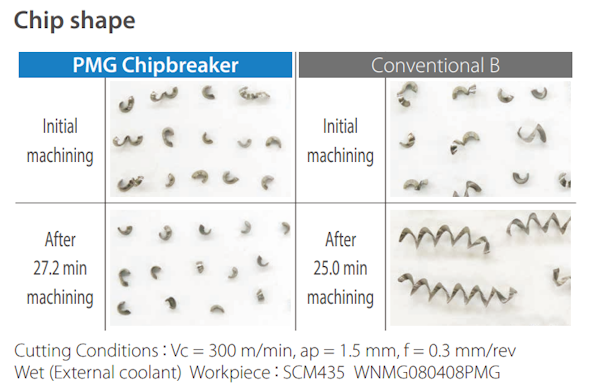
Short broken fragments | Brittle material or very aggressive chip breaking | Normal in cast iron, but excessive fragmentation in steel may signal high impact, an overly strong breaker, or unstable engagement. |
The variables that move a process into or out of the chipbreaker window
Feed per revolution usually has the strongest immediate effect. Increasing feed thickens and stiffens the chip, so it pushes more firmly into the chipbreaker and is easier to fracture. This is why a finishing chipbreaker designed for 0.05-0.15 mm/rev may fail when the programmed feed drops well below its lower limit.
Depth of cut changes the chip width and the length of cutting edge in contact. If depth of cut is too small for a medium or roughing geometry, the chip may interact only with the nose area and miss the intended groove. If it is too large, the wider chip can become difficult to steer and may exceed the geometry’s capacity.
Cutting speed affects temperature, friction, and material flow. Higher speed often makes chips more continuous in ductile steels. Reducing speed may help break a chip in some cases, but it can also promote built-up edge and hurt surface finish. Speed should therefore be adjusted after checking whether the insert geometry, feed, and depth of cut are correctly matched.
Tool angles change the undeformed chip thickness and its direction. A larger entering angle generally produces a thicker, narrower chip at the same feed and depth of cut, which can improve breakage. A more positive rake lowers cutting force but usually makes the chip easier to flow and harder to break. A negative land adds edge strength and deformation, but also raises cutting force. A larger nose radius can spread the cut and reduce effective chip thickness, which may make light finishing chips harder to control.
Coolant delivery also matters. A well-directed high-pressure jet can lift and steer the chip, shorten tool-chip contact, and improve chip breakage in stainless steel and heat-resistant alloys. A poorly aimed flood stream may cool the process without changing chip flow.
How to select a chipbreaker for roughing, medium turning, and finishing
Start with the insert supplier’s application map for the exact workpiece material group. Then place the planned feed and depth of cut inside the geometry’s recommended zone. Do not select a chipbreaker only by labels such as F, M, or R; those codes are manufacturer-specific.
For roughing, prioritize edge support, chip capacity, and predictable evacuation. A wider, stronger geometry accepts heavier chip load but may not break chips in a light cut.
For medium turning, look for the broadest stable window that covers normal variation in stock allowance. This is often the best first choice for general production because it tolerates modest changes in feed and depth of cut.
For finishing, the geometry must engage at low chip thickness without making the edge fragile. A sharp positive cutting action reduces radial force and protects the surface. The preferred chip is often an open or tight helix that leaves the workpiece cleanly. Small C-shaped chips can be acceptable if they do not strike the finished diameter.
Troubleshooting poor chip control
Symptom | Likely cause | Practical correction |
Long ribbon chips at a light finish cut | Feed and depth of cut are below the chipbreaker’s range; nose radius is large relative to chip thickness | Move to a finishing geometry, increase feed within finish requirements, or reduce nose radius. |
Chip nest around the chuck or toolholder | Chip flows in the wrong direction or never reaches a breaking point | Check insert hand and holder orientation, use a geometry with better steering, improve coolant direction, and verify feed. |
Chips scratch the finished diameter | Curl direction sends the chip back toward the surface | Change chipbreaker or entering angle, redirect coolant, or adjust tool path so the chip exits into free space. |
Insert chips shortly after improving chip breakage | Groove is too aggressive, chips pack in the pocket, or cutting force exceeds edge strength | Use a stronger geometry, open the chip space, reduce feed or depth of cut, and check tool overhang and workholding. |
Chip shape changes as stock allowance varies | One chipbreaker is being used outside its depth-of-cut window | Use a broader medium geometry or split the operation into roughing and finishing tools. |
Good chips but unstable surface finish | Repeated chip impact, built-up edge, or excessive force variation | Favor a freer-cutting finishing geometry, check speed and coolant, and confirm that chips are not hitting the workpiece. |
A practical evaluation method for production trials
Record chip shape together with the actual cutting condition. A photo of a good chip is not useful unless it is tied to material grade, hardness, insert designation, corner radius, feed, depth of cut, speed, coolant method, and tool overhang.
During a trial, change one variable at a time. Feed is usually the first lever, followed by depth of cut if stock allowance permits. Inspect whether the chipbreaker is engaged and whether the chip contacts the workpiece, flank, or holder. Watch the finished surface for chip marks and check the insert edge for chipping or crater wear.
The best setup is not the one that makes the shortest chip in a ten-second test. It is the one that keeps chip form, tool life, surface finish, and machine uptime stable across the full batch.

Conclusion
Turning chip control is a geometry-and-conditions problem. Chipbreaker groove width, depth, radius, orientation, and local rake features set the intended curl, while feed and depth of cut determine whether the chip reaches that geometry with enough stiffness to break. Cutting speed, entering angle, rake, nose radius, coolant, and setup rigidity then shift the result.
When specifying carbide turning inserts, send the supplier the real operating window rather than one nominal cutting condition. HNCarbide can use the workpiece material, hardness, operation type, depth-of-cut range, feed range, stability limits, and target surface finish to recommend a more suitable insert geometry and grade for production testing.