Through-Tool Coolant Pressure Levels in CNC Machining:A practical selection guide for pressure, flow, chip control, and system design
Table of Contents

A coolant pump may show 70 bar on its nameplate while the cutting edge receives far less useful energy. Restrictions in the rotary union, toolholder, sealing interfaces, drill channels, and nozzles all change the pressure and flow that reach the cut. That is why buying a higher-pressure pump alone does not guarantee shorter chips, cooler cutting, or longer tool life.
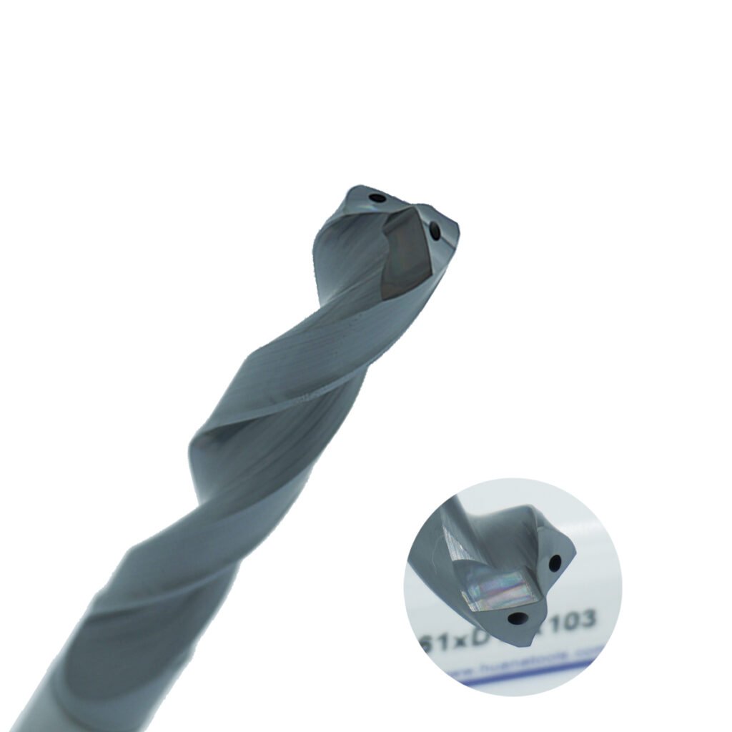
Through-tool coolant works when the entire delivery chain is matched to the operation. The fluid travels through the spindle, turret, holder, or cutting tool and exits close to the cutting edge. It is less likely than flood coolant to be blocked by the workpiece or a growing chip nest. The practical result can be better heat removal, lubrication, and chip evacuation, especially in deep holes, enclosed pockets, and turning operations that produce long, ductile chips.
This guide uses four working pressure bands to compare systems. They are useful for process planning and supplier discussions, but they are not a universal industry standard. Machine builders and tooling companies often use different labels. Always confirm the rated pressure, available flow, filtration requirement, permitted spindle speed, and pressure limit of every component in the coolant path.
What through-tool coolant changes at the cutting edge
External flood coolant must travel around the tool, workpiece, fixture, and chips. In open milling, that may be adequate. In a hole 10 diameters deep or behind the chip in a turning cut, the stream often cannot reach the hottest contact zone. Internal delivery shortens that path and makes the outlet position repeatable after a tool change.
Pressure and flow do different jobs. Pressure gives the jet velocity and penetration needed to reach the interface and influence chip curl. Flow carries heat and transports chips out of the cut. A very small orifice can create high pressure with too little volume to clear a large drill flute. A large passage may deliver plenty of flow but lower pressure at the outlet. The correct balance depends on tool diameter, number of outlets, coolant viscosity, hole depth, and chip volume.
Haas, for example, offers through-spindle coolant systems around 21 bar and 69 bar. Its application guidance connects these systems with deep-hole drilling, deep pocketing, higher feed rates, and chip removal. Sandvik Coromant reports visible chip-control benefits at 35 bar in some stainless-steel turning work and recommends 70 bar for difficult chip breaking with suitable high-precision holders and insert geometries. These are application-specific reference points, not proof that one pressure suits every machine.
A practical four-level pressure framework
The ranges below organize common shop-floor applications. Use them as a starting point. The actual pressure at the cutting edge may be lower than the pump setting, and required flow rises with tool diameter and the number of coolant outlets.
Working level | Nominal pressure | Typical flow reference | What it usually provides | Common applications |
Low-pressure internal coolant | Up to 20 bar (2 MPa) | 10-30 L/min | Basic cooling and chip flushing; limited jet penetration | General cutting, semi-finishing, finishing, shallow pockets, short holes |
Medium-pressure internal coolant | 20-50 bar (2-5 MPa) | 15-40 L/min | Stronger delivery into the cut and better evacuation; chip breaking remains geometry-dependent | General production machining, moderate-depth holes, enclosed features |
High-pressure coolant | 50-100 bar (5-10 MPa) | 20-50 L/min | High-velocity jet, improved access to the tool-chip interface, and greater influence on chip curl | Stainless steel, titanium, deep holes, deep cavities, unattended turning |
Ultra-high-pressure coolant | Above 100 bar (10 MPa) | 30-60 L/min or application-specific | Strong chip-lifting and chip-breaking effect, with demanding sealing and filtration requirements | Nickel alloys, difficult stainless grades, Swiss-type work, severe chip-control problems |
The flow values are indicative rather than design specifications. A 3 mm drill and a multi-outlet face mill cannot be sized from the same chart. Ask the machine and tool suppliers for pressure-flow curves at the intended outlet area.

Low-pressure internal coolant: up to 20 bar
Low-pressure delivery puts coolant in a better location than an external hose, even when the jet does not have enough energy to influence chip formation. It is useful for finishing, light milling, short-hole drilling, and general work where heat and chips are manageable.
Its limitation appears when a continuous chip shields the interface or a deep hole traps swarf. More pump pressure may help, but first check whether the tool has suitable internal channels and whether the outlet points at the rake face or flute. Poor direction wastes pressure.
Medium-pressure internal coolant: 20 to 50 bar
This range covers many production machines equipped with through-spindle coolant. It can improve delivery in moderate-depth drilling and enclosed pockets without the cost and maintenance burden of a 70-bar or higher system.
Expect more reliable cooling and flushing, not automatic chip breaking. Insert geometry, feed per revolution, depth of cut, material condition, and jet position still govern chip shape. If long stainless-steel chips persist, increasing pressure within this band may produce only a small change unless the holder and chipbreaker were designed for precision coolant.
High-pressure coolant: 50 to 100 bar
High-pressure systems become attractive when chips interrupt production. A well-aimed jet can enter the space between the chip and rake face, reduce contact length, lift the chip, and tighten its curl. In ductile materials, this may turn long ribbons into pieces that leave the work zone without wrapping around the tool or component.
The same jet improves access to a region that conventional flood coolant struggles to reach. This matters in austenitic stainless steel, titanium alloys, and heat-resistant superalloys, where heat tends to remain close to the cutting edge. Tool life gains depend on stable delivery. Pulsation, a clogged filter, or pressure loss through a restrictive connection can erase the expected benefit.

Ultra-high-pressure coolant: above 100 bar
Pressures above 100 bar are used where chip control is severe enough to justify a specialized system. Examples include nickel-based alloys, oil-cooled Swiss-type machines, and operations that cannot tolerate stringy chips. The stronger jet can produce a pronounced chip-lifting effect, but it also magnifies weaknesses in the system.
Rotary unions, turret seals, hoses, fittings, holders, collets, and tools must all carry the rated pressure. Fine filtration becomes more important because a small particle can block a precision nozzle or damage a close-tolerance pump. Higher pressure also adds heat to the coolant through pumping and may require more tank capacity or temperature control.
The five process effects that matter
1. Heat removal where heat is generated
Most cutting heat is created by material shearing and friction at the tool-chip contact. Internal channels place coolant close to those sources instead of cooling the general enclosure. Lower edge temperature can slow diffusion, oxidation, plastic deformation, and thermal cracking, although the dominant wear mechanism changes with tool material and operation.
Do not assume that the workpiece will always run cooler just because the pump pressure is higher. If flow is starved, the jet may have high velocity but insufficient heat-carrying capacity. Record both pressure and flow during trials.
2. Lower friction and less adhesion
Coolant that reaches the rake and clearance faces can reduce sliding friction and limit material adhesion. This is useful when stainless steel, aluminum, or other ductile materials tend to form a built-up edge. A more stable interface often improves surface finish and dimensional consistency.
Lubrication also depends on fluid chemistry and concentration. Pressure cannot compensate for a poorly maintained emulsion, bacterial degradation, excessive tramp oil, or the wrong additive package.
3. Chip evacuation before recutting occurs
In drilling, the coolant must push chips along the flutes and out of the hole. In pocket milling, it should prevent chips from collecting where the cutter will strike them again. In turning, the objective is often to move broken chips away from the component and chuck.
Re-cut chips damage cutting edges and can mark finished surfaces. A stable internal stream reduces this risk, but outlet size and flute space still matter. Large chip volume requires enough flow, not pressure alone.

4. More controllable chip formation
At high pressure, a jet directed at the rake face can lift the chip and reduce its curl radius. Seco describes this effect in its Jetstream tooling, where accurately positioned coolant cools the chip and lifts it from the rake face. Sandvik similarly notes that chip breaking depends on insert type, pressure and flow, and accurate jet direction.
This is why a standard holder with an improvised hose rarely matches a holder designed around fixed precision nozzles. The repeatable outlet angle is part of the cutting system.
5. More stable production, not simply faster cutting
The strongest business case is often fewer interruptions. Short, controlled chips reduce manual clearing, tool damage, surface scratches, and the risk of a chip nest stopping an unattended cycle. Longer tool life can reduce changeovers and offset checks. Higher cutting data may follow, but it should come after the process is stable.

Match pressure to the machining problem
Machining condition | Starting pressure approach | What to verify during the trial |
Short-hole drilling in steel or cast iron | Low to medium pressure may be sufficient | Complete chip exit, flute packing, thrust load, hole size and finish |
Deep-hole drilling above about 8-10xD | Medium or high pressure with adequate flow | No pecking requirement, outlet flow at depth, filter loading, tool temperature |
Austenitic stainless-steel turning | High pressure with a precision-coolant holder | Chip length, chip direction, notch wear, built-up edge, surface damage |
Titanium or nickel-alloy turning | High pressure; consider above 100 bar only with approved tooling | Edge temperature symptoms, flank wear, chipping, seal condition, coolant temperature |
Deep pocket milling | Medium to high pressure depending on cutter diameter | Chip re-cutting, pocket packing, available flow through all outlets |
Finishing where chips are already controlled | Low or medium pressure | Dimensional stability, finish, foaming, unnecessary pump energy |
The useful trial is not “70 bar versus flood coolant” with every other variable changed. Keep the tool, geometry, cutting data, concentration, and measurement method constant. Compare chip form, tool wear after a fixed cutting time, cycle interruptions, surface finish, and coolant temperature. Then decide whether the next pressure step pays for itself.
System details that decide whether high pressure works
Tool and holder pressure ratings
Every interface must be approved for the selected pressure. A cutting tool with internal holes is not automatically suitable for 100 bar. Confirm the maximum rating for the spindle union, turret, holder, reduction sleeves, seals, fittings, and tool. Leakage at one interface reduces performance and can contaminate spindle or turret components.

Filtration and coolant cleanliness
Small outlets require clean fluid. Cutting Tool Engineering reports that filtration requirements become finer as pressure rises, with example systems using filters in the 10-25 micrometre range and some pumps requiring even finer protection. The correct specification depends on pump design, rotary union, and nozzle diameter.
Tank capacity, return flow, and heat
A pump that draws coolant faster than the machine returns it will cavitate or pulse. The tank must have enough working volume, settling capacity, and return flow for the selected duty cycle. Higher pump power also adds heat. If dimensional tolerance is tight, monitor coolant temperature rather than treating thermal control as a separate issue.
Pressure at the tool, not at the pump
Pressure losses occur across hoses, valves, rotary unions, holder interfaces, and small internal channels. Install measurement points close to the spindle or turret where possible. A pressure switch at the pump confirms that the pump is working; it does not confirm that a blocked drill is receiving coolant.
Coolant concentration and foaming
Higher agitation can expose a marginal coolant mix. Check the supplier’s recommended concentration, water quality, defoaming behavior, and compatibility with high-pressure pumps. Foam reduces pump stability and can make tank-level readings misleading.
A buyer’s checklist for a through-tool coolant package
Question for the machine, pump, or tooling supplier | Why it belongs in the purchase specification |
What pressure and flow are available at the tool outlet for the proposed tool diameter? | Pump ratings alone do not show usable delivery at the cut. |
Which components are rated for the maximum pressure and spindle speed? | Prevents seal, union, hose, and holder failures. |
What filtration level is required, and how is a blocked filter detected? | Protects the pump and prevents nozzle blockage. |
Can the system select different pressure setpoints by tool or operation? | Avoids wasting energy and over-pressurizing light-duty tools. |
Is the machine tank large enough for the required flow and duty cycle? | Reduces starvation, aeration, pulsation, and thermal drift. |
What maintenance is required for filters, pump oil, seals, and concentration control? | Converts the purchase price into a realistic operating cost. |
Can the supplier support a cutting trial on the actual material and feature? | Confirms chip control and tool-life value before full production release. |
Common mistakes when upgrading internal coolant
The first is specifying pressure without flow. The second is assuming that any through-coolant tool will survive the maximum system pressure. A third common mistake is keeping the old filtration arrangement after installing smaller nozzles and a tighter pump. Those errors lead to weak performance, leaks, clogging, or premature pump wear.
Another mistake is raising pressure before correcting chipbreaker selection and cutting data. High-pressure coolant supports chip control; it does not replace the mechanical conditions needed to bend and break a chip. In some finishing operations, the chip is too thin to break regardless of pressure.
Finally, shops sometimes apply the highest setting to every tool. That adds energy consumption and heat while increasing stress on seals and small tools. A system with programmable pressure by tool number is usually more useful than one fixed at its maximum output.

How to choose the right level
Start with the failure mode. If the problem is flute packing in a deep hole, prioritize through-tool flow and a clear return path. If stainless-steel chips wrap around the component, examine insert geometry, feed, nozzle position, and high-pressure capability together. If finish drifts during a long cycle, record coolant temperature and concentration before buying a larger pump.
For many shops, 20-50 bar is a sensible production range for general through-spindle work. Operations involving deep holes, titanium, austenitic stainless steel, or unattended turning often justify 50-100 bar. Pressures above 100 bar should be treated as an engineered process with rated tooling, fine filtration, adequate tank capacity, and a measured return on investment.
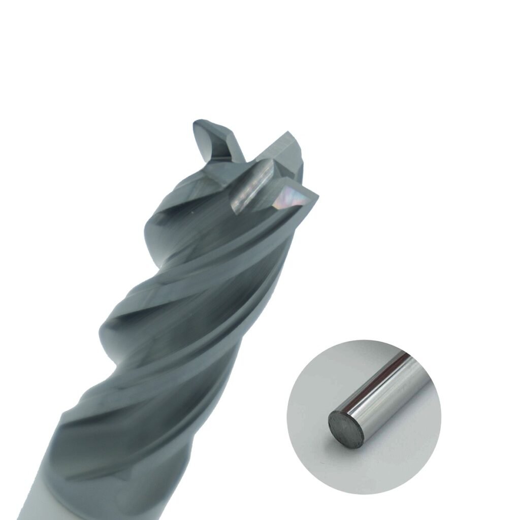
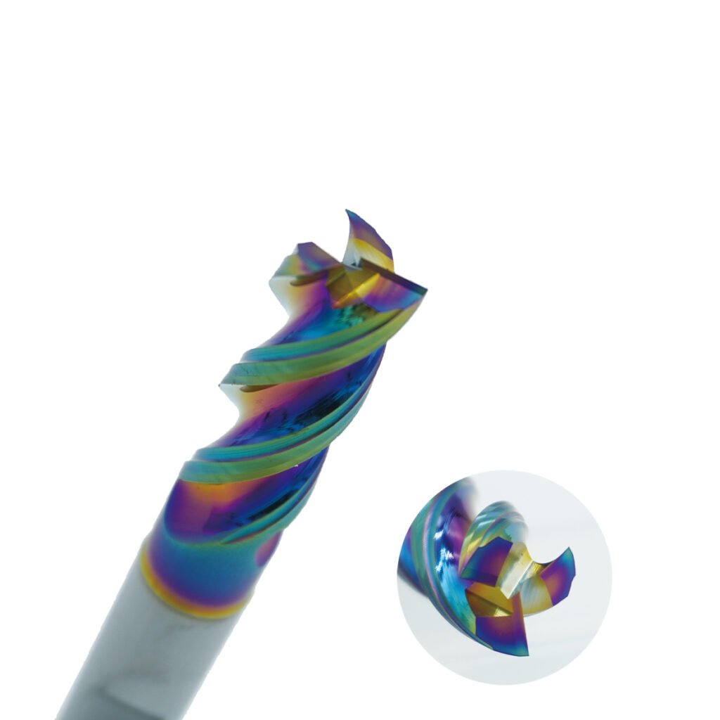
HNCarbide can help review the cutting-tool side of that system, including internal-channel tool selection, coolant-hole geometry, and application requirements. The useful specification is not simply a pressure number. It is a matched combination of pressure, flow, direction, filtration, and tool geometry that reaches the cutting edge consistently.