 Skip to content
Thermal Deformation of Cutting Tools in Precision Machining
Table of Contents
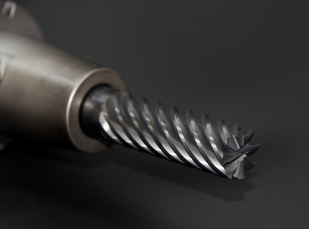
Precision machining is often discussed through geometry: spindle runout, machine accuracy, fixture rigidity, tool wear, and inspection method. Those factors matter, but they do not explain every drifting bore, every taper that appears late in a batch, or every finish pass that behaves differently after the machine has been cutting for an hour.
Heat is the quiet variable behind many of those changes. In fine turning, hard milling, mold finishing, jig grinding, micro-machining, and other tight-tolerance work, a few microns of thermal growth can move a part from stable production to repeated adjustment. Some machining studies report that thermal effects can account for a large share of total error in precision operations, sometimes in the 40% to 70% range. The exact number depends on the machine, process, material, duty cycle, and measurement method, but the direction is clear: when tolerances move into the micron range, thermal behavior becomes a process variable, not background noise.
For carbide tooling, the problem is easy to underestimate. The insert or end mill may be small, stiff, and made from a material that tolerates very high cutting temperatures. That does not mean it stays dimensionally still. The cutting edge sits in a severe thermal gradient. It is heated by chip formation and friction, cooled by chips, coolant, air, and the toolholder, and loaded mechanically at the same time. The result is not a neat textbook expansion. It is a moving geometry at the point where the part is being made.
Where the heat comes from
Most tool heating starts with cutting heat. When the cutting edge shears metal, the material ahead of the edge deforms plastically. At the same time, friction occurs between the chip and rake face, and between the flank face and the freshly machined surface. A large portion of the mechanical energy becomes heat.
Much of that heat leaves with the chip. The exact heat split changes with material, speed, feed, depth of cut, tool geometry, coating, coolant, and chip shape. In many turning examples, only a smaller portion enters the tool compared with the chip, but the cutting edge has very little thermal mass. Even a modest heat share can create a high local temperature rise.
Carbide tools can see extremely high edge temperatures in severe cutting. Published examples and shop experience often place hot-zone temperatures in the hundreds of degrees Celsius, and in demanding conditions the cutting edge can approach or exceed 1000 deg C. At that level, the issue is no longer only tool wear. Thermal expansion, coating stress, softened work material, built-up edge, and thermal cracking may all become part of the accuracy problem.
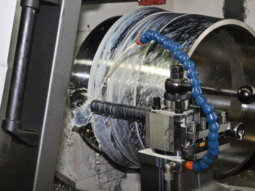
The heat source is not limited to the cutting zone. Spindles, bearings, ball screws, motors, hydraulic units, coolant temperature, and the shop environment all influence the relative position between tool and workpiece. On some machines the spindle and main drive dominate thermal drift. On others, hydraulics, long-axis travel, or enclosure temperature matter more. The cutting tool is only one part of the thermal chain, but it is the part that directly touches the tolerance.
How tool thermal growth becomes a part error
Thermal deformation matters because it changes the intended relative position between the cutting edge and the workpiece. In turning, a tool that grows radially toward the workpiece effectively increases depth of cut. The machined diameter can become smaller as the tool warms. In boring, the same idea may appear as a bore size shift. In milling, thermal movement of the spindle, holder, or cutting edge can change wall location, floor flatness, parallelism, and surface texture.
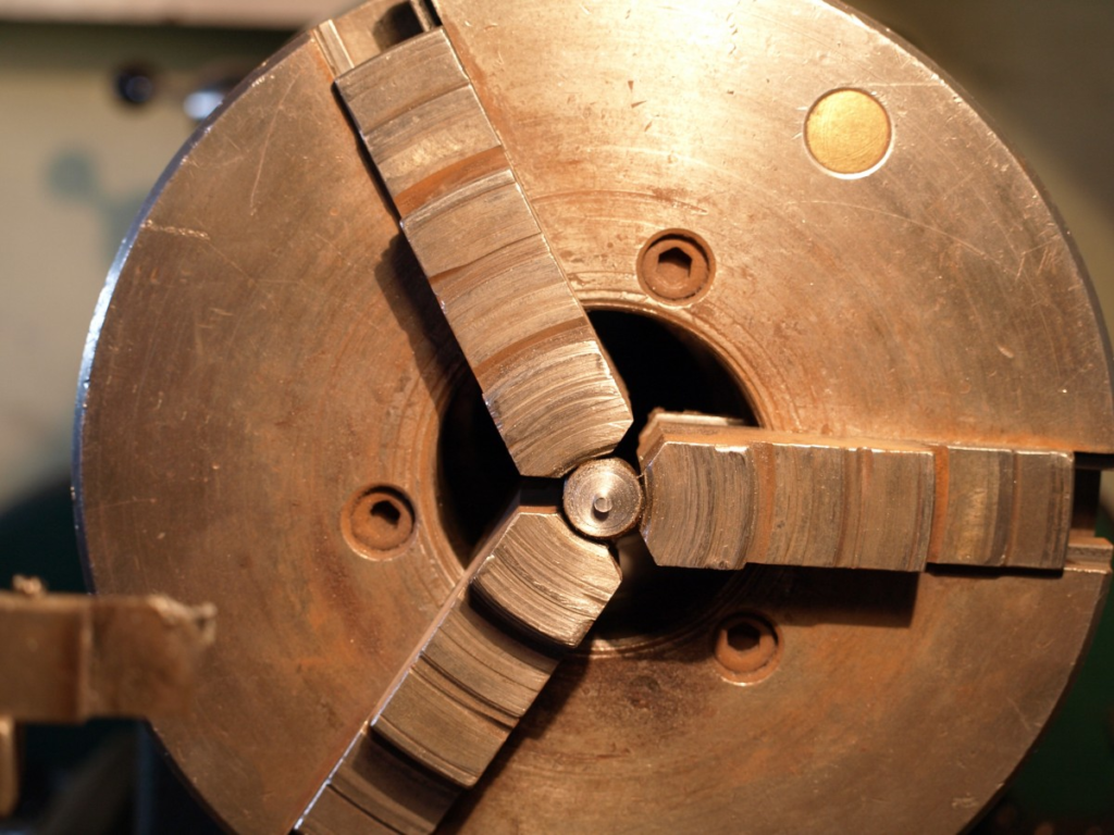
The hard part is that the error is time-dependent. At the beginning of a production run, the machine, holder, tool, and workpiece may be near ambient temperature. As cutting continues, temperature rises until heat input and heat removal move toward balance. During that warm-up period, dimensions can drift even though the program, tool offset, fixture, and operator method have not changed.
That makes thermal deformation especially troublesome in batch production. The first few parts may measure differently from the parts made after thermal stabilization. If the operator adjusts offsets too early, later parts may drift in the opposite direction. If the shop ignores the warm-up period, it may mistake thermal drift for random tool wear or machine instability.
Thermal growth also interacts with wear. A worn flank face increases rubbing and heat. Higher cutting speed raises heat generation. Longer tool overhang increases the sensitivity of the tool system to both mechanical and thermal displacement. A tool can therefore become less accurate as it wears, not only because the edge geometry changes, but because the thermal state changes with it.
Typical symptoms in precision machining
Thermal deformation rarely announces itself as a single obvious failure. It usually appears as a pattern. A machinist may see a diameter that trends smaller over time in OD turning, a bored hole that walks after several parts, a milled wall that needs offset correction after warm-up, or a fine finishing pass that produces different roughness at the end of a long cycle.
Symptom on the part or process | Likely thermal contribution | Practical check |
Dimensions drift in one direction during the first parts of a batch | Tool, holder, spindle, or machine structure is warming toward steady state | Measure parts by sequence number and compare with spindle/load time |
Finish pass cuts heavier after a long roughing cycle | Tool length, radial edge position, or spindle position has shifted with heat | Separate roughing and finishing measurements; check tool offset trend |
Bore size changes after tool wear increases | Worn edge produces more rubbing heat and changes thermal expansion | Inspect flank wear and compare bore size before and after insert change |
Flatness or parallelism shifts on milled surfaces | Spindle or tool system tilts as temperature changes | Probe reference surfaces before and after warm-up |
Offset correction works briefly, then needs another correction | The process has not reached thermal equilibrium | Track temperature, cycle time, and part size together |
These checks are simple, but they are powerful because they separate thermal drift from random noise. If part size follows time in cut, spindle warm-up, coolant temperature, or tool wear progression, the shop has a thermal problem to control. If size changes randomly with no trend, the root cause may be fixture movement, chip recutting, inspection variation, or another mechanical issue.
Modeling and simulation: useful, but not magic
For high-value parts and tight tolerance processes, thermal behavior can be modeled. Finite element analysis is widely used to estimate the temperature field and deformation of cutting tools under defined cutting loads and heat flux. More detailed models may include tool wear, changing contact length, chip-tool friction, and coolant boundary conditions.
Simulation is useful because it shows where the tool system is sensitive. It can help engineers compare toolholder materials, overhang length, insert geometry, internal cooling channels, or compensation strategies before cutting expensive parts. It can also explain why a process that looks stable mechanically still produces thermal dimensional drift.
In production, however, the model must be grounded in measurement. Cutting conditions vary. Coolant nozzles move. Inserts wear. Operators change tools. Raw material lots behave differently. A practical model should therefore be treated as a decision aid: it narrows the variables, points to the likely heat path, and supports compensation, but it should not replace part measurement and process trials.
Control methods that work on the shop floor
Thermal deformation can be reduced in two ways: prevent excessive heat from entering the tool system, and compensate for the remaining movement. Most stable processes use both.
The first layer is process control. Cutting speed, feed, radial engagement, axial depth of cut, and tool path strategy all affect heat input. Reducing heat does not always mean slowing everything down. In milling, a better chip load and engagement strategy may move heat into the chip instead of rubbing it into the edge. In turning, a sharper geometry or more suitable chipbreaker may reduce friction. In hard materials, conservative finishing data may be necessary, but too light a cut can also rub and heat the edge.
Tool geometry and toolholding come next. A shorter overhang reduces sensitivity to both force and thermal growth. Rigid holders, clean tapers, balanced tools, and repeatable clamping help prevent thermal drift from being mixed with mechanical movement. Carbide grade and coating also matter because they influence heat resistance, friction, and wear behavior at the cutting edge.
Coolant strategy is another major lever. Flood coolant, high-pressure coolant, through-tool coolant, minimum quantity lubrication, and dry machining each create different thermal behavior. Coolant should reach the cutting zone, not merely wet the outside of the holder. For deep holes, narrow slots, and high-speed finishing, poor coolant access can leave the cutting edge hot even when the machine looks flooded.
Control area | What to adjust | Why it helps |
Cutting parameters | Speed, feed, engagement, depth of cut, step-over, finishing allowance | Controls heat generation and where heat leaves the cut |
Tool and holder | Shorter overhang, stable clamping, suitable carbide grade, coating, edge prep | Reduces sensitivity to thermal and mechanical displacement |
Cooling | Nozzle position, coolant pressure, through-tool delivery, coolant temperature | Removes heat and keeps thermal conditions repeatable |
Process timing | Warm-up cycle, consistent cycle sequence, roughing/finishing separation | Avoids critical finishing while the system is still drifting |
Inspection feedback | First-off checks, in-process probing, trend charts, wear inspection | Separates thermal drift from wear, setup, and measurement noise |
For some applications, material choice in the toolholder can help. Low-expansion alloys and specially designed internal cooling structures have been studied for reducing thermal deformation. They are not universal answers, because stiffness, cost, damping, clamping method, and machinability of the holder must also be considered. Still, they show a useful principle: thermal stability should be designed into the tool system, not treated only as an offset problem.
Compensation closes the loop
Once thermal drift is measurable and repeatable, compensation becomes practical. The simplest form is procedural: warm the machine and tool system before producing critical dimensions, then inspect after the process reaches a stable state. Many shops already do this informally, but documenting the warm-up time and the expected dimensional trend makes it more reliable.
More advanced compensation uses temperature sensors, spindle load data, process time, probing results, or non-contact measurement to estimate thermal growth. The CNC can then apply a coordinate shift, tool-length correction, or axis compensation value. In research and high-end production, machine-learning models are increasingly used to predict thermal error from multiple temperature points and process variables.
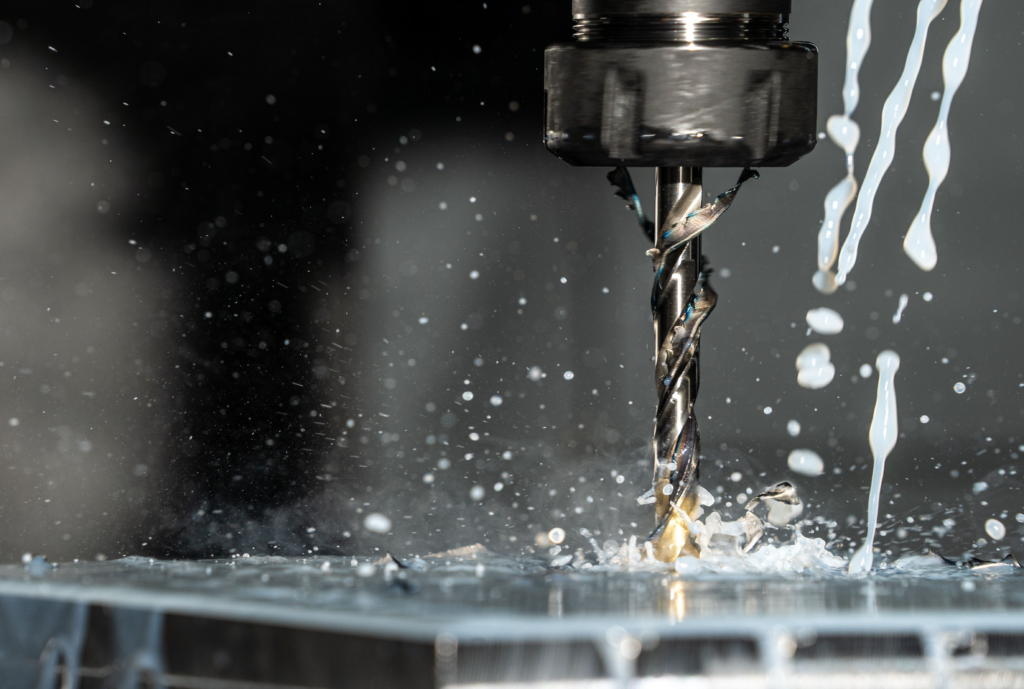
Compensation should be introduced carefully. A weak model can make the process worse by correcting the wrong axis, overreacting to temporary changes, or hiding a coolant or wear problem that should be fixed directly. The best sequence is usually measurement first, root-cause reduction second, compensation third.
A practical troubleshooting workflow
When a precision process shows unexplained dimensional drift, start with a short controlled study. Run the machine from cold or from a defined warm condition. Measure the same feature on each part in order. Record cycle time, spindle time, coolant state, tool number, tool wear, and any offset changes. If possible, measure a reference feature that should not be affected by the cutting tool in the same way.
Then look for trend, not just tolerance failure. If the first five parts move quickly and later parts stabilize, warm-up is likely. If drift accelerates as the insert wears, wear-driven heat is likely. If the dimension changes after a long roughing cycle but recovers after idle time, heat soak in the spindle, holder, or workpiece may be involved. If only one feature shifts, the issue may be local tool growth or tool path order.
Question to ask | Useful evidence | Typical action |
Does the error follow time in cut? | Sequential part measurements show a warm-up curve | Add a warm-up routine or schedule critical finishing after stabilization |
Does the error follow tool wear? | Size drift increases with flank wear or edge rounding | Change insert life limit, geometry, coating, or coolant delivery |
Does the error follow coolant condition? | Drift changes with coolant temperature, pressure, or nozzle position | Stabilize coolant temperature and improve delivery to the cutting zone |
Does the error follow operation order? | Finishing after heavy roughing produces a different result | Split roughing and finishing, add dwell/cooling time, or revise sequence |
Is drift repeatable enough to model? | Similar curve appears across repeated runs | Apply controlled offset compensation or sensor-based correction |
This kind of study does not require a laboratory. It requires disciplined data collection and a willingness to stop treating offsets as isolated events. Once the trend is visible, the right fix becomes much easier to justify.

Conclusion
Tool thermal deformation is not an exotic problem reserved for ultra-precision laboratories. It appears anywhere cutting heat, tool wear, process time, and tight tolerances meet. In rough work, the effect may be hidden inside a generous tolerance band. In precision machining, it can become the difference between a stable process and a batch that needs constant correction.
The practical answer is not a single coolant, coating, model, or compensation algorithm. It is a controlled system: reduce unnecessary heat, keep the tool and holder rigid, deliver coolant where it matters, allow the machine to reach a predictable thermal state, and use measurement data to compensate only when the drift is repeatable.
For shops selecting carbide end mills, drills, or turning inserts for tight-tolerance work, HNCarbide can help match tool geometry, grade, coating, and application data to the thermal demands of the process. The goal is simple: keep the cutting edge productive without letting heat quietly move the tolerance.





