
T-Slot Cutter Milling Fixture Design: How Workholding Affects Quality and Efficiency
Table of Contents
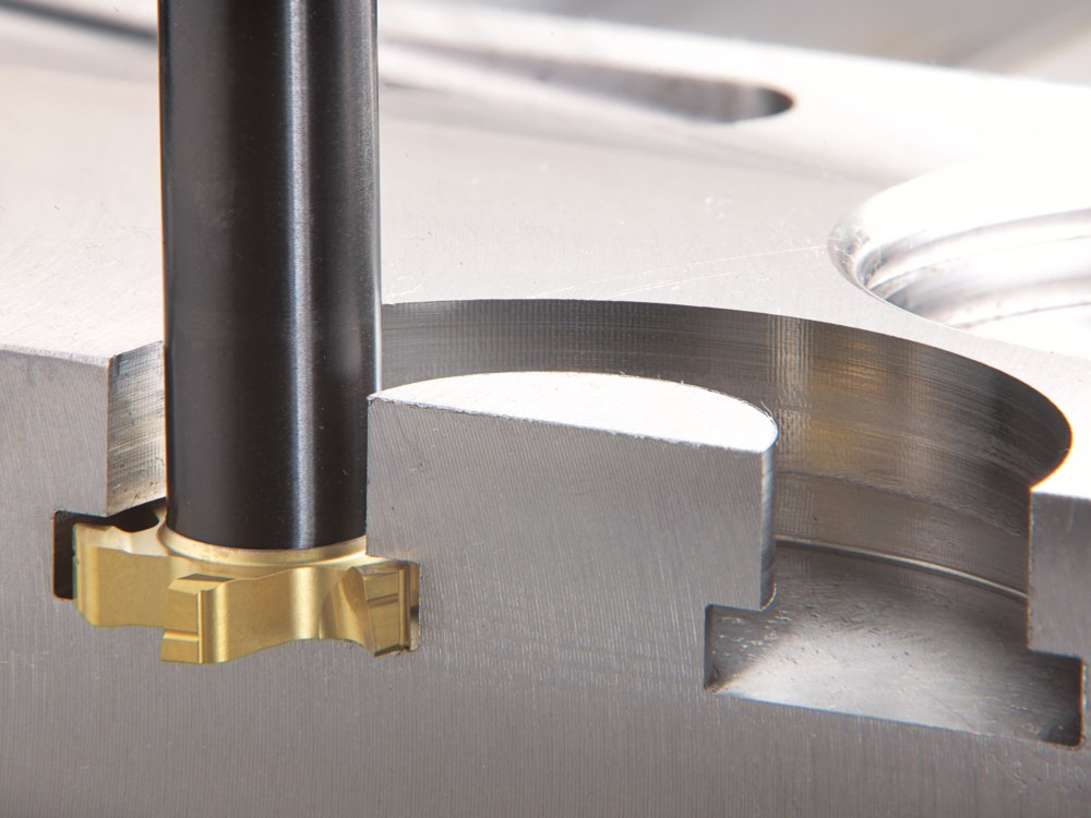
A T-slot cutter is rarely the forgiving part of a milling setup. The tool enters a narrow slot, cuts on a hidden side face, and often works with limited chip space. If the workpiece lifts, the clamp relaxes, or chips pack inside the groove, the result can be a noisy cut, poor slot size, damaged edges, or a broken cutter.
That is why fixture design matters so much in T-slot milling. The cutter, machine tool, and workholding system behave as one process. A rigid machine and a sharp carbide T-slot cutter still cannot produce stable slots if the fixture allows vibration or pushes the part in the wrong direction.
This guide explains how to choose and design milling fixtures for parts machined with T-slot cutters. It is written for CNC shops, tooling buyers, process engineers, and production teams that need more consistent slot quality and better cycle efficiency.
Why T-Slot Milling Is Sensitive to Fixture Quality
T-slot milling is more demanding than many open-face milling operations because the cutting forces are less visible and less forgiving. The cutter is typically working inside or below the top surface of the workpiece. Chips have fewer ways to escape. The tool overhang may be longer than a standard end mill. Cutting force changes as each tooth engages and exits the material.
In practical shop-floor terms, the fixture must control four things at the same time:
Process risk | What happens in the cut | Fixture requirement |
Part lifting | Slot width, flatness, and location drift as the workpiece rises from the datum | Clamp force should push the part into its locating surfaces |
Vibration | Chatter marks, burrs, chipped cutter teeth, poor finish | Fixture body, supports, and clamp points need enough stiffness |
Chip packing | Recuts chips, heat rises, cutter edge breaks down | Provide chip space, coolant flow, and an escape path |
Wrong fixture orientation | Slot location changes from part to part | Use reliable locating keys, stops, and repeatable setup references |
This is also why lubrication and coolant should not be treated as afterthoughts. A T-slot cutter run dry or with poor chip evacuation is easier to chip, especially in steel, stainless steel, and interrupted cuts. The right cutting fluid, oil mist, or coolant strategy depends on the material and machine, but the fixture should not block that fluid from reaching the cutting zone.
Main Milling Fixture Types Used Around T-Slot Cutter Work
Milling fixtures can be grouped by how the workpiece feeds through the cut and how production is organized. The categories are not just textbook labels. They point to real differences in cycle time, part loading, and fixture cost.
Fixture type | Typical use | Strengths | Watch-outs for T-slot milling |
General adjustable milling vise or modular fixture | Prototype, repair, small batch, mixed part families | Fast setup, low tooling cost, easy adjustment | Needs custom jaws or stops when datum control is critical |
Linear-feed fixture | Worktable feeds in a straight line during milling | Simple machine relationship, good for slot features along one axis | Fixture must resist cutter torque and vibration during the long feed stroke |
Indexing fixture or rotary table fixture | Multi-face milling, angular slots, repeated indexed positions | Repeatable angles and fewer manual resets | Added fixture height can reduce rigidity and tool clearance |
Multi-part fixture | Batch production with several parts per cycle | Higher spindle utilization and shorter handling time per part | Clamp force must be balanced so all parts locate equally |
Linked or pneumatic clamping fixture | Medium to high volume production | Fast loading, consistent clamping force | Requires good maintenance and fail-safe clamp confirmation |
Circular continuous-feed fixture | Large-volume work on rotary table or rotary milling equipment | Loading and unloading can happen while other parts are cutting | More complex fixture timing, guarding, and process control |
For small-batch T-slot work, a milling vise with dedicated jaws is often the most practical answer. For higher-volume parts, the fixture usually becomes more specialized: multiple parts, linked clamps, air or hydraulic actuation, and fixed locating features that reduce operator judgment.
Selecting the Fixture Based on Production Volume
Fixture cost only makes sense when it is compared with the cost of bad parts, slow loading, and cutter failures. A shop making ten pieces should not build the same fixture as a shop making ten thousand. At the same time, a cheap setup that breaks cutters every shift is not really cheap.
For prototypes and small batches, start with a standard milling vise, precision parallels, stops, and custom jaws if the part geometry requires it. The key rule is to direct cutting force toward the fixed jaw whenever possible. If the cutting force tends to pull the part upward or away from the fixed jaw, the setup may look solid at rest but move during the cut.
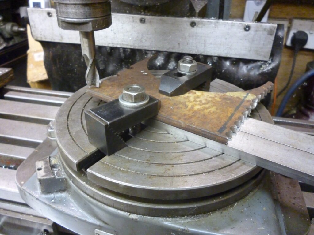
For small to medium batches, adjustable fixtures, subplates, and indexing devices can reduce setup time while keeping flexibility. A graduated rotary table or indexing plate is useful when parts need several angular positions or multiple milled faces. The operator can position the part repeatably without building a fully dedicated fixture.
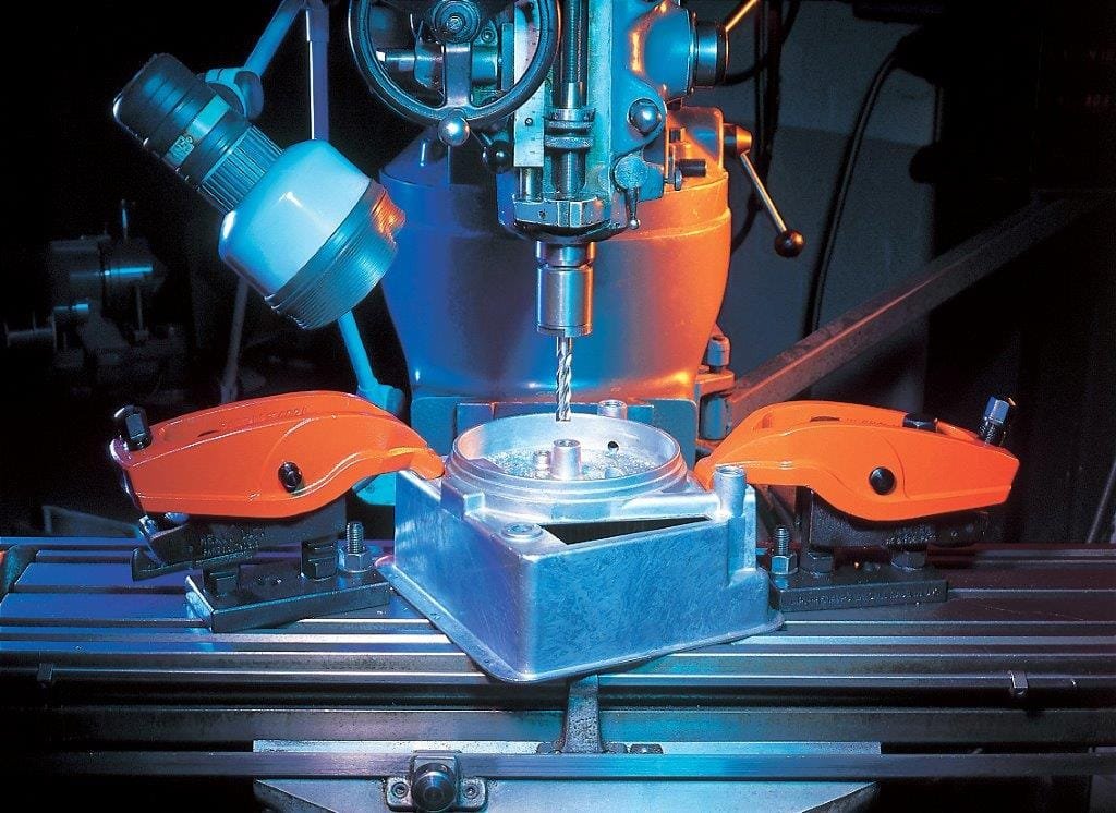
For high-volume production, dedicated fixtures become easier to justify. A good production fixture may hold several workpieces, use linked clamps, or use pneumatic or hydraulic clamping to reduce loading time. The best designs remove small operator decisions: the part drops against defined locators, clamps apply force in the intended direction, and chips do not collect on the datum surfaces.
Structural Design Requirements for T-Slot Cutter Fixtures
T-slot cutter operations create variable cutting forces. Milling is an interrupted process, and the force direction can change as the cutter tooth enters and exits the material. If the workpiece has extra stock, scale, casting variation, or uneven roughing allowance, the cutting load can be even less predictable.
A fixture for this work should therefore be designed for rigidity first. Keep the fixture as low as practical, keep the workpiece close to the machine table, and avoid tall narrow fixture bodies. As a practical guideline, the fixture height-to-width relationship should stay conservative; a fixture that is tall compared with its base is more likely to vibrate or rock under side load.
The workpiece surface being machined should not hang far outside the support area unless the design includes strong auxiliary support. Overhang turns cutting force into leverage. That leverage shows up as chatter, taper, slot mismatch, or clamp loosening.
Locating Rough Castings, Forgings, and Uneven Blanks
If the fixture locates on a machined datum, the design problem is usually straightforward. If it locates on a casting, forging, saw-cut blank, or rough flame-cut surface, the fixture must tolerate real blank variation.
For cast and forged blanks, fixture design should be based on the blank drawing as well as the finished part drawing. The fixture needs to account for draft, parting lines, gate or riser marks, scale, and uneven stock allowance. A locator placed where a casting feature varies too much can make the fixture unreliable even if the finished part model looks simple.
Auxiliary supports are often needed when rough surfaces are used for location. These supports should not fight the primary locators. Their job is to prevent deflection and vibration after the part has already seated against the main datum surfaces. Adjustable supports, screw jacks, or self-aligning pads can be helpful when blank variation is expected.
Thin walls, long ribs, and unsupported ears deserve extra attention. T-slot milling can pull or push these features enough to create spring-back. The slot may measure correctly in the fixture but shift after unclamping. If the part relaxes after machining, add support near the cutting zone or revise the machining sequence so the most flexible areas are not cut last under high load.
Clamp Force Direction: The Detail That Often Decides the Setup
A clamp is not good just because it is tight. It must push the part in a direction that helps the locating scheme.
When clamping from the side, the clamp force should act lower than the side support point or be arranged so the combined force presses the part into the supporting surfaces. If the clamp acts too high on the workpiece, it can create a tipping moment. The part may lift from the primary datum, especially when the cutter adds side force.
The clamp point should also be close to the part’s centerline or mass center when possible. This reduces twisting and helps distribute force evenly across the support points. For irregular parts, a floating pad or two-point pressure pad can make the clamp more stable than a single hard contact point.
Self-locking matters as well. Milling vibration can relax a weak clamp, especially in long cuts. Wedges, toggle mechanisms, screw clamps, and properly designed mechanical advantage devices can help maintain force. In production fixtures using air or hydraulic clamping, the design should include enough holding margin and a practical way to confirm clamp status.
Tool Setting, Fixture Keys, and Machine Table Alignment
T-slot cutter work usually needs careful tool-to-fixture alignment. A small shift in cutter position can change slot symmetry, undercut width, or wall clearance. For manual and semi-automatic setups, tool setting blocks, feeler gauges, or setting gauges should be placed where the operator can see and use them easily.
The tool setting device should normally be located near the end where the cutter begins entering the workpiece. That makes setup more intuitive and reduces the chance of checking the wrong side of the fixture.
For fixtures mounted to a milling machine table, the bottom of the fixture body should use locating keys when repeatable alignment is needed. Two keys spaced far apart help align the fixture with the machine table T-slots and reduce the load carried only by the hold-down bolts. Even when the feature being cut is not strictly parallel to the table axis, keys can improve setup stability because they resist the torque created by cutting forces.
Chip Evacuation and Coolant Access
T-slot cutter fixtures need real chip space. If the fixture traps chips under the part or around the slot, the next part may not sit on the datum. If chips pack inside the groove, the cutter may recut them and break an edge.
Good fixture design leaves open channels for chips and coolant. Avoid closed pockets below the cutting area unless they are easy to clean. Add reliefs, chip wells, drain holes, or sloped surfaces where appropriate. If coolant is used, make sure the fixture does not block coolant from reaching the cutter and does not trap fluid in a way that creates corrosion or cleaning problems.
For dry machining, air blast or vacuum extraction may be needed. This is especially important in aluminum, cast iron, and materials that produce small chips or dust. For steel T-slot milling, coolant or cutting oil can reduce heat and improve tool life, but it still needs a path to reach the hidden cutting edge.
Common T-Slot Milling Problems and Fixture-Related Fixes
Problem seen on the part or cutter | Likely fixture-related cause | Practical correction |
Slot width varies from part to part | Part shifts against movable jaw or unstable stop | Push cutting force toward fixed locators; add positive stops |
Chatter inside the T-slot | Fixture too tall, weak support near the cut, excessive overhang | Lower fixture height, add support, shorten tool overhang where possible |
Cutter teeth chip early | Workpiece vibration, chip packing, poor coolant access | Improve clamping stiffness, add chip clearance, revise coolant/air delivery |
Burrs or poor finish on one side | Part tilts under side clamp or lifts from datum | Lower clamp contact point, add floating pad or auxiliary support |
Operator spends too long loading parts | Too many loose clamps, unclear part location | Use dedicated jaws, linked clamps, hard stops, or multi-part fixture design |
Good first part, drifting later parts | Chips collect on locating surfaces | Add chip relief and cleaning access; keep datum pads away from chip flow |
These fixes sound simple, but they are often what separates a stable production process from a setup that depends on one experienced operator’s feel.
Final Thoughts
T-slot cutter performance is not only a tool problem. It is a system problem. The cutter needs enough rigidity, chip room, lubrication, and force control to work as intended. A fixture that looks strong on the bench may still fail in the cut if it lets the part lift, traps chips, or places clamping force too high.
For occasional work, a good vise setup with custom jaws and careful support may be enough. For repeated production, dedicated fixtures with repeatable location, balanced clamping, and open chip paths usually pay back through fewer rejects, faster loading, and longer cutter life.
HNCarbide supplies carbide cutting tools for milling, drilling, turning, and custom machining applications. If your T-slot milling process is limited by tool life or slot consistency, the best starting point is to review the cutter, fixture, material, coolant, and feed strategy together rather than changing only one variable.


