 Skip to content
Stainless Steel End Mills vs General Purpose Carbide End Mills
Table of Contents
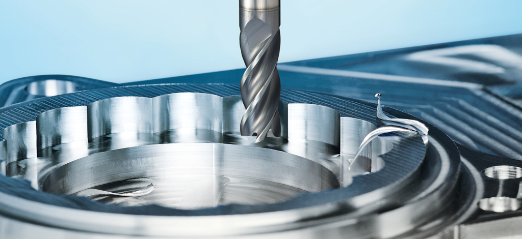
A carbide end mill that runs reliably in carbon steel can start leaving burrs, squealing in corners or losing its cutting edges when the next job is 316L. The diameter may be correct and the tool may still be sharp. What has changed is the relationship between the workpiece, the cutting edge and the programmed toolpath.
Stainless steel end mills are designed around those demands. Compared with a general purpose carbide end mill, they may use different rake geometry, flute spacing, edge preparation and coating. Both tools can be made from solid carbide. A stainless-specific label describes the intended application, rather than a separate class of tool material.
For a CNC shop, the useful question is whether a dedicated design keeps the cut stable and maintains part quality through the planned tool life. This guide focuses on solid carbide end mills, with particular attention to common austenitic grades such as 304 and 316L.
What the tool names actually mean
A general purpose end mill is intended to cover a range of materials and routine operations. It can be a sensible choice for a shop making short runs in several steels. Some general purpose carbide tools also list stainless steel in their application range.
A stainless steel end mill gives more design attention to a particular material group or cutting strategy. That might mean a versatile four-flute cutter for pockets and shoulders, or a higher-flute-count tool intended for controlled radial engagement. Neither name defines a universal geometry.
Tool application ranges overlap. A variable-geometry carbide end mill may support both steel and stainless steel, while another design is optimized for a narrower material group or cutting strategy. Check the recommended alloy conditions, radial engagement and operation limits for the exact cutter instead of relying on its name alone.
Selection factor | General purpose carbide end mill | Stainless-focused carbide end mill |
Intended use | Routine work across a stated material range | Selected stainless grades or demanding stainless operations |
Substrate | Solid carbide is common | Solid carbide is also common; grade choice supports the application |
Cutting geometry | Compromise across supported materials | Geometry selected for cutting forces, adhesion and edge durability |
Flute arrangement | Conventional or variable geometry | Variable pitch or helix may help control vibration |
Coating | May be coated or uncoated | Heat and wear resistant coating often specified |
Main application test | Does it maintain the required finish and tool life? | Does it improve stability and consistency in the intended operation? |
Why stainless steel exposes weaknesses in a milling setup
Austenitic stainless can work harden when it is deformed. An edge that repeatedly rubs or takes an ineffective cut can leave a more difficult surface for the next tooth. Adhesion at the cutting edge can also disturb chip formation and damage the finish.
The consequences are familiar at the machine: burrs that need extra deburring, inconsistent finish and edge damage before the planned tool change. Built-up edge and smearing can disturb the finish, while rubbing can leave a hardened surface for subsequent teeth. When the chip becomes too thin for effective shearing, reducing feed further can increase wear rather than protect the edge.
These effects do not mean every failed stainless operation requires a different cutter. A long tool projection, poor workholding or chips trapped inside a pocket can overwhelm a well-chosen tool. Before changing the tool series, inspect the setup and determine where the failure starts. Damage concentrated on one flute suggests a different investigation from uniform wear on every flute.
Tool material matters but it is not the whole difference
Comparing a stainless end mill with an ordinary high-speed steel cutter can create a misleading impression. In production CNC work, the more relevant comparison is often between two solid carbide tools.
Carbide substrate selection involves tradeoffs among wear resistance, toughness and the support needed at the edge. The best balance depends on the workpiece condition and how the tool enters the cut. A hard, wear-resistant grade cannot compensate for repeated impacts in an unstable setup, and simply asking for the hardest carbide does not define a suitable cutter.
Cobalt high-speed steel tools remain an option in some lower-speed applications, but that is a separate selection question. Do not assume that every general purpose tool is HSS or that every tool marketed for stainless has a unique substrate. Ask the supplier to identify the tool material, supported stainless grades and recommended operating conditions.
For repeat purchasing, also specify the cutting diameter, shank tolerance, corner form and usable cutting length. Those details affect whether a replacement will run in the existing holder and program without adjustment.
Geometry controls how the edge meets the workpiece
Rake angle and edge preparation
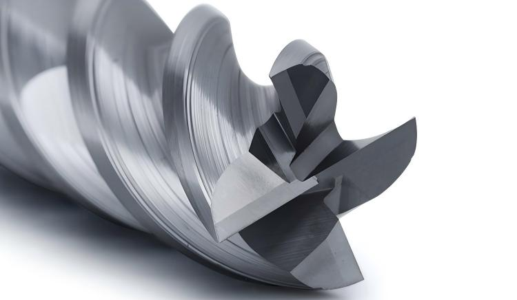
A positive rake can reduce the effort required to shear the material. The edge still needs sufficient support for the intended cut. Extremely sharp geometry and heavy edge reinforcement serve different purposes; a good stainless design balances them for its application.
Rake angle, helix and core diameter need to work together. A geometry that reduces cutting pressure still requires enough core support for the intended reach and engagement. Unequal flute spacing can alter the timing of tooth engagement and help control vibration, but it cannot compensate for a loose fixture or excessive tool projection.
An edge hone or chamfer can support a vulnerable edge, but excessive preparation can make a light cut less effective. When the application involves thin walls or a small finishing allowance, ask whether the supplier recommends the same edge preparation used for roughing. A tool chosen only for strength may put more pressure on the part than the finishing operation can tolerate.
Flute count and chip space
More flutes can increase the number of cutting edges passing the workpiece at a given spindle speed. They also change the space available for chips and the stiffness of the tool cross-section. That tradeoff has to be evaluated against radial engagement and pocket access.
A full-width slot gives chips a more confined route out of the cut than an open side-milling pass. Choosing a high-flute-count cutter because it performs well in dynamic milling does not establish that it will perform equally well in a deep slot.
A higher-flute-count cutter can suit controlled-engagement roughing when the toolpath keeps the radial cut light and provides room for chip removal. A slotting operation places different demands on chip space. Select the flute count for the actual operation; neither four nor six flutes is a universal requirement for stainless steel.
Coatings support the edge under heat and wear
A coating should be assessed together with the substrate and cutting geometry. Titanium aluminum nitride based systems and other modern PVD coatings appear in carbide tool ranges that support stainless milling. General purpose tools may use these systems too.
Coated general purpose and stainless-focused end mills can use similar coating families. Differences may lie in the formulation, layer structure and operating window, together with the substrate and edge geometry. Compare the complete cutter specification rather than assuming that any coated tool is automatically suitable for stainless steel.
Color is a poor purchasing specification. Two visually similar coatings can have different formulations, and a coating name alone does not prove better performance in your cut. Request the recommended workpiece range and cutting data for the complete tool.
Corrosion resistance is rarely the main reason to choose a cutting-tool coating for this comparison. The production concern is whether the cutting edge keeps performing through the planned machining cycle. A coating cannot correct chatter, chip recutting or a program that repeatedly overloads the cutter in corners.
Cutting parameters need an operation specific starting point
Reducing speed, feed and depth together may make the first cut quieter, but it can also hide the cause of the problem. Use the supplier’s data for the exact cutter, material condition and operation. A finishing recommendation at light radial engagement should not be copied into a slotting program.
Feed per tooth and maximum chip thickness are related, but they are not always equal. In peripheral milling below half-diameter radial engagement, radial chip thinning reduces maximum chip thickness. Feed compensation may be needed to maintain the intended cut, within the tool and machine limits.
For an arithmetic example only, a five-flute cutter at 4,000 rpm and a programmed feed per tooth of 0.03 mm gives a table feed of 600 mm/min: spindle speed multiplied by flute count multiplied by feed per tooth. These numbers are not a stainless machining recommendation. Whether that feed produces an appropriate chip depends on engagement, edge geometry and the supplier’s limits.
Operation | Tool selection focus | Programming and setup focus |
Full-width slotting | Documented slotting capability and chip space | Slotting-specific depth and feed; clear chip exit route |
Dynamic roughing | Tool approved for controlled radial engagement | Manage engagement through corners and entry moves |
Open shoulder milling | Edge stability and usable cutting length | Keep projection short and check actual cutting width |
Thin-wall finishing | Low cutting pressure and adequate reach | Control deflection and avoid ineffective repeated passes |
Confined pocket milling | Chip evacuation and access | Direct coolant where required and prevent chip recutting |
Coolant recommendations depend on the cutter and cut
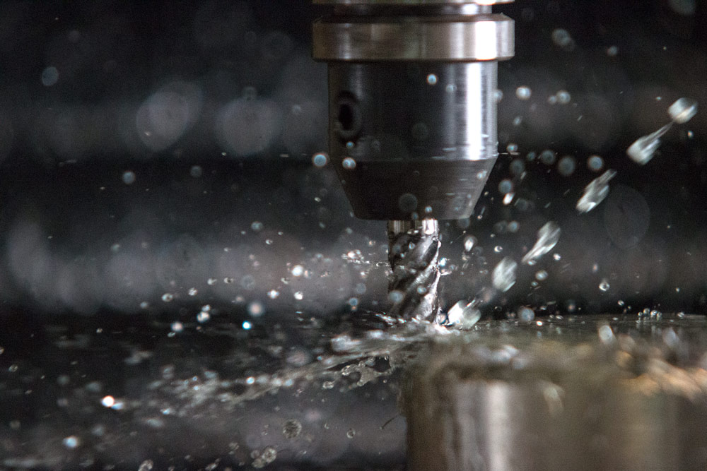
Coolant delivery should match the cutter and the operation. In confined pocketing, fluid can help lubricate the contact and carry chips out of the cut. Internal delivery can reach areas that an external nozzle misses, provided the tool, holder and machine support the required supply.
Some indexable stainless roughing recommendations favor dry cutting to reduce thermal cracking. That guidance should not be transferred automatically to a small solid carbide end mill in a confined pocket. Follow the recommendation for the actual tool system and maintain consistent delivery when wet machining is specified.
Check where the coolant goes during the whole path. A nozzle that reaches the tool at the pocket entrance may miss it at the bottom. If chips remain behind the cutter, another pass can recut them regardless of the quality of the coating. Through-tool delivery can help in supported designs, but the holder and machine must provide the required supply.
Choose for the stainless grade and its condition
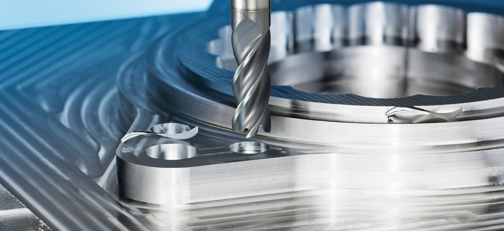
Stainless steel is a family of materials. A tool trial in 304 does not establish the same result in hardened martensitic stainless or an aged precipitation-hardening grade. Obtain the grade, heat treatment and hardness before selecting the cutter.
Ferritic, martensitic, austenitic and duplex grades have different machining requirements. Ferritic stainless may behave more like low-alloy steel, whereas austenitic grades often require particular attention to adhesion and work hardening. Hardened material calls for a tool and cutting strategy suited to its actual hardness, regardless of the stainless designation.
For a tooling buyer, the purchase description should include the actual alloy and condition as well as the operation. If the shop machines 17-4PH, specify its condition rather than sending only the alloy name. If the problem occurs in a deep pocket, include the depth and tool projection. The supplier can then assess the application instead of recommending a cutter from a broad material label.
How to validate a stainless end mill on the machine
A general purpose carbide tool remains suitable when it is approved for the material and consistently meets the job’s quality and tool-life requirements. A stainless-focused design is worth testing when edge damage is unpredictable, burr formation increases during a run, or vibration prevents the shop from maintaining the intended cut.
Compare the cutters on the same part with comparable holders, tool projection and workholding. Record the workpiece grade and condition, coolant delivery and programmed engagement. Each cutter should run within its own recommended operating window; forcing different geometries to use identical settings can obscure how they perform in their intended applications.
Set the acceptance criteria before starting. Use the drawing’s dimensional and finish requirements, together with an agreed tool-change limit. Inspect parts at defined intervals so the comparison captures how quality changes as the edges wear, rather than judging only the first part.
Trial measure | What to record | Why it matters |
Usable tool life | Acceptable parts or cutting time before the agreed limit | Shows how long the tool maintains required quality |
Dimensional consistency | Measured feature sizes at defined intervals | Reveals drift as wear or deflection changes |
Surface quality | Required finish and burr condition | Checks whether the finishing result remains consistent |
Failure pattern | Flank wear, chipping, adhesion or breakage | Helps explain early or unpredictable tool changes |
Chip evacuation | Chip accumulation and signs of recutting | Checks whether flute geometry and delivery suit the operation |
For a 316L pocketing trial, inspect the pocket walls and burr condition near the start of the run and again at the same intervals for each cutter. Examine the cutting edges when a tool reaches the agreed limit. If damage repeatedly concentrates on one flute, check runout and holder condition before attributing the result to the tool design. If chips remain trapped in the pocket, address their exit route and coolant access before repeating the comparison.
Repeat a promising result with another tool of the same specification. A repeatable wear pattern and consistent part quality provide a stronger basis for process approval than a single successful run.

Selecting a tool that fits the job
The main differences between stainless steel end mills and general purpose carbide end mills lie in how the complete tool is matched to the application. Geometry, edge preparation, coating and flute arrangement work together, and the result still depends on engagement, workholding and chip removal.
Keep a proven general purpose cutter where it meets production needs. Trial a stainless-focused design where recurring wear, finish problems or cycle-time limits make the potential gain measurable. When discussing an HNCarbide end mill for a stainless job, provide the alloy condition, operation, cutting depth and machine setup so the tool recommendation can be evaluated against the actual part.





