 Skip to content
Solid Carbide Thread Milling Cutters: How to Specify, Program, and Run Them Like a Pro
Table of Contents

Thread milling has moved from “niche” to “default” in high-value manufacturing. Compared with tapping, it offers better control over tolerances, chip evacuation, and tool life—especially in difficult materials and small-batch, high-mix production. This guide explains what a solid carbide thread mill is, how it works, and how to choose, program, and troubleshoot it. I’ve woven in your technical notes (accuracy levels, coatings, geometry, parameters, and brand landscape) and added practical tips from the shop floor. Three tables are included for quick reference.
What Is a Solid Carbide Thread Milling Cutter?
A solid carbide thread milling cutter is a rotary end mill engineered to generate internal or external threads via helical interpolation (typically G02/G03). Made from sub-micron grain carbide (hardness around HRA 92+), it offers high stiffness, high wear resistance, and thermal stability. Designs range from short, rigid cutters for blind holes to longer-reach tools with through-coolant for deep or gummy materials. Multi-tooth forms increase productivity and suppress vibration by distributing the load.
Key performance envelope (from your spec):
Thread quality: up to IT6–IT7 with surfaces around Ra 0.8 μm when parameters and setup are optimized.
Materials: steels, stainless steels, titanium, nickel-based superalloys, and other hard-to-cut alloys.
Thread directions: right-hand and left-hand; suitable for blind and through holes.
Why Thread Mill Instead of Tap?
Taps are fast and simple when the thread, material, and batch size are stable. But thread mills win when the application demands accuracy, flexibility, tool life, and chip control. The cutter machines a helical path; pitch, diameter, and class are defined by CNC motion, not by a rigid, single-purpose tool. One cutter can produce multiple diameters of the same pitch, and—within reason—even different pitch classes by offset.
Thread Milling vs. Tapping
Criterion | Thread Milling (solid carbide) | Tapping (conventional) |
Achievable precision | High: IT6 (typ.), IT7 with robust settings; roundness and lead control by toolpath | Moderate: IT7–IT8 typical; geometry fixed by the tap |
Tool life | Long (carbide substrate, optimized coatings) | Shorter (HSS/HSCo), sensitive to torque spikes |
Material range | Broad, works well in stainless, Ti, Ni-alloys, hardened steels | Limited by torque and chip packing, especially in blind holes |
Flexibility | One tool can cut multiple diameters of the same pitch; easy left/right threads; taper threads via path | Each tap = one size/pitch/direction; special taps for each standard |
Chip control | Excellent. Chips are small, evacuated along flute; through-coolant helps | Risk of jam (especially blind holes); broken taps can scrap parts |
Process risk | Lower—path can be verified, cutting forces are controllable | Higher—tap breakage risks scrap and time-consuming removal |
Cycle time | Competitive. Multi-tooth mills close the gap; single-tooth slower | Fast in soft materials and large pitches |
Single-Flute Cutter Catalog
Click the button below to view our single-flute cutters and detailed specs to choose the right tool.
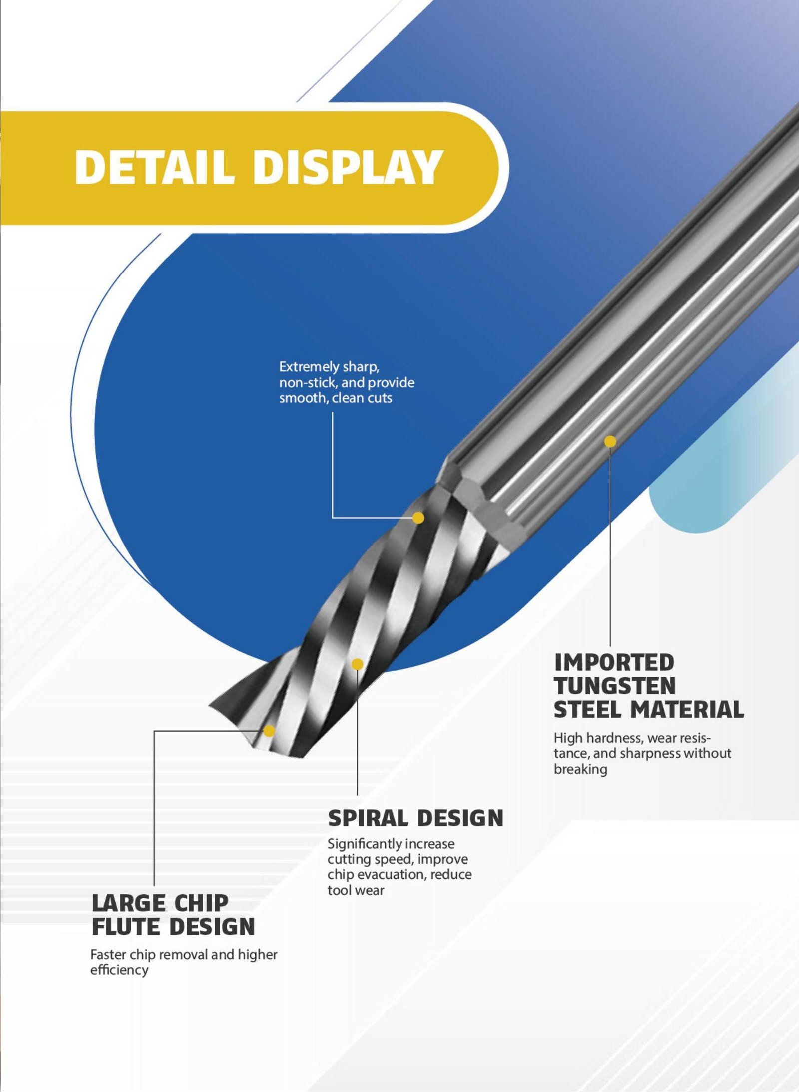
Core Features (What to Look For)
Ultra-fine-grain carbide body (HRA 92+) for stiffness and wear resistance.
Multi-tooth geometry (3–6 flutes depending on diameter) to raise metal removal rate and reduce chatter.
Optional through-coolant to enhance chip evacuation in deep/ blind holes and high-temperature alloys.
Shank styles: cylindrical or with a ground flat; pick what matches your holder and anti-pull-out strategy.
Coatings tailored to the material: TiAlN/AlTiN/AlCrN for ferrous alloys, TiCN for sticky stainless, DLC/TiB₂ or uncoated polished for aluminum, and diamond-like for abrasive composites.
Typical Ranges and Standards
The table below consolidates the reference ranges you gave and adds context for selection on the shop floor.
Technical Parameters (Typical Ranges)
Parameter | Range / Options | Notes |
Tool diameter (Dc) | Ø3–Ø20 mm | Choose based on minor/major diameter and clearance |
Pitch range (P) | 0.5–3.0 mm | Finer pitches favor more teeth; coarser pitches need stronger teeth |
Number of teeth (z) | 3–6 | More teeth = higher feed at same fz; ensure chip room |
Shank | Cylindrical or with flat | Match to ER/heat-shrink/side-lock; minimize runout |
Coatings | TiAlN, TiCN, diamond-like (optional) | Select by material (see §6) |
Thread standards | Metric (M), UNC/UNF, NPT | Metric and inch are both feasible; taper threads via toolpath |


Where Thread Milling Excels
Aerospace: engine cases, landing gear components, housings—often Ti or Ni alloys with stringent lead/position tolerances.
Automotive: cylinder blocks and drivetrain housings where chip evacuation is critical.
Medical devices: implants and fixtures requiring high-class threads and burr-free flanks.
Energy: oil & gas valves, turbine components, high-temperature-alloy parts that punish taps.
Selection Guide (Material → Geometry/Coating)
A clean selection framework prevents 80% of problems. Use the matrix below to pick coatings, tooth count, and coolant strategy.
Quick Selection Matrix
Material / Situation | Coating | Teeth (z) | Coolant style | Notes |
Carbon & alloy steels | TiAlN / AlCrN | 3–5 | External (flood/MQL) | Stable tool, good heat resistance |
Stainless steels | TiAlN / TiCN | 3–4 | Through-coolant preferred | Control adhesion; avoid rubbing |
Titanium & high-temp Ni alloys | AlTiN / AlCrN (polished flutes) | 3–4 | Through-coolant | Keep engagement light; evacuate chips |
Aluminum & non-ferrous | Uncoated polished or TiB₂/DLC | 4–6 | External or through | Prevent built-up edge; high fz possible |
Abrasive composites | Diamond-like | 3–4 | External | Reduce flank wear |
Fine pitch (P ≤ 1.0 mm) | As above | 4–6 | As above | More teeth = smoother finish |
Coarse pitch (P > 1.0 mm) | As above | 3–4 | As above | Stronger tooth, bigger chip room |
Deep/ blind holes | As above | 3–4 | Through-coolant | Prioritize chip evacuation |
Starting Cutting Data (and How to Scale Them)
From your notes for M10 × 1.5 in steel:
Cutting speed (Vc): 80–120 m/min
Feed per tooth (fz): 0.03–0.08 mm/tooth
Radial depth of cut (ae): ≤ 0.5 × Dc (and often far less for difficult alloys)
Scaling tips
Increase Vc toward the top of the range in carbon steels and with stable, coated tools; reduce for stainless, Ti, and Ni alloys.
Use the low end of fz when the setup is long-reach, threads are fine pitch, or the material is sticky; raise fz if chips smear or the tool rubs.
For coarse pitches or hard materials, split the depth into two or three radial passes to control forces and deflection.
Workholding, Runout, and Tool Life
Runout control is non-negotiable. Keep spindle/holder/runout ≤ 0.01 mm (TIR) at the cutting length. This directly affects flank finish and pitch diameter.
Stickout: keep it as short as possible; small-diameter mills are inherently slender.
Holders: heat-shrink or precision ER with collet runout verification. Anti-pull-out systems are valuable on aggressive feeds.
Coolant: through-coolant wins for deep blind holes and heat-resistant alloys. For aluminum, a clean, lubricious external coolant or MQL prevents built-up edge.
Deburring: program a quick spring pass or reverse helix lead-out to minimize burrs at the top land.

Troubleshooting (Fast Diagnostics)
Poor flank finish / roughness too high (Ra > spec):
Verify runout ≤ 0.01 mm; check collet/seat contamination.
Drop fz slightly or add a finish pass at reduced radial step.
For stainless/Ti, confirm coolant concentration/pressure and consider a sharper edge prep or TiCN/AlCrN coating.
Edge chipping or premature wear:
Material hardness over target? Confirm with hardness test.
Reduce radial engagement; split the cut.
Switch to a tougher coating; ensure no coolant starvation (especially on entry).
Chip packing, especially in blind holes:
Use through-coolant and/or shorter passes with timed evacuation.
Increase helix lead-out to fling chips clear; avoid dwell at the bore bottom.
Thread undersize/oversize:
Tune path offset ±0.005–0.02 mm at the pitch diameter.
Re-probe tool length and verify deflection isn’t driving the error (long stickout, high ae).
FAQ
Can one tool cut multiple diameters?
Yes—same pitch threads of different diameters can be milled by changing the helical radius. The cutter geometry sets the flank profile; the CNC sets the size.
What about taper threads (NPT)?
Feasible via a tapered helical path. CAM posts usually include NPT thread-milling cycles—verify taper per inch and gauge depth.
Is single-tooth or multi-tooth better?
Multi-tooth boosts productivity on rigid machines. Single-tooth offers ultimate flexibility and is safer in interrupted or unstable setups.
How do I hit IT6 consistently?
Control runout, temperature, and toolpath smoothing; probe the bore, apply small radial comp adjustments, and add a light finish pass.
Conclusion
Solid carbide thread milling has become the high-precision, high-flexibility answer for modern threading—particularly in stainless, titanium, and superalloys where taps struggle. With the right coating and tooth count, clean helical programming, and disciplined runout control, you can hit IT6–IT7 threads with Ra 0.8 μm surfaces, reduce risk, and—on many jobs—achieve dramatic end-to-end productivity gains by eliminating tap-related scrap and downtime.


