
Solid Carbide End Mill Structure and Its Role in Modern CNC Machining
Table of Contents
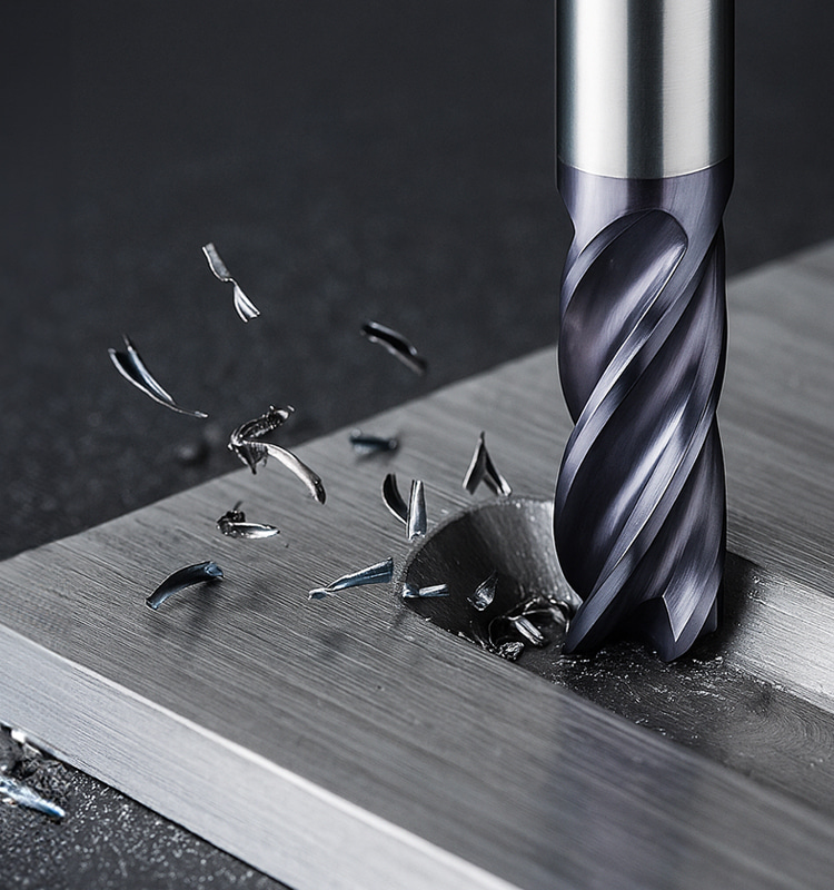
In a CNC shop, the end mill is a small part of the total machine investment, but it can decide whether a job runs smoothly or turns into a cycle of chatter, tool changes, scrap, and missed delivery dates. A solid carbide end mill affects surface finish, dimensional control, cycle time, spindle load, and tool cost per part. That is why engineers and tooling buyers should look beyond diameter and flute count and understand how the cutter is built.
This guide explains the structure of a solid carbide end mill from the inside out: carbide grade, flute geometry, end shape, coating, cutting data, and common failure modes. The goal is practical selection, not catalog memorization.
What “Solid Carbide” Really Means
“Solid carbide” does not mean the tool is made from pure carbide. Most carbide end mills are made from cemented carbide, a composite material built mainly from tungsten carbide particles held together by a metallic cobalt binder. The tungsten carbide phase supplies hardness, wear resistance, and hot strength. The cobalt binder adds toughness, so the tool can survive interrupted cuts, vibration, and changing chip loads.
The balance is important. A very hard grade can hold an edge well in abrasive work, but it may chip if the setup is unstable. A tougher grade can tolerate shock and less-than-perfect machines, but it may wear faster in high-speed finishing or hard materials. That tradeoff sits behind many catalog recommendations.
Grain size also matters. Fine-grain and submicron carbide grades can support sharper cutting edges and better wear resistance, which is useful for small tools, finishing, hardened steel, and precision work. Coarser or tougher grades may be preferred when the cutter sees heavy load, long overhang, interrupted engagement, or roughing in less rigid conditions.
For purchasing teams, this means two cutters with the same size and coating may behave differently if the carbide grade is different. For process engineers, it means tool life problems are not always solved by changing feeds and speeds. Sometimes the substrate is simply wrong for the job.
Geometry Is the Cutter’s Working Language
The visible shape of an end mill is not decoration. Flute count, helix angle, rake, core diameter, corner form, and pitch all influence how chips leave the cut and how force enters the tool.
Two-flute and three-flute cutters leave more chip space, so they are common in aluminum, plastics, and slotting operations where chips are larger and need room to escape. Four-flute cutters are a common starting point for steel because they offer a stronger core and more cutting edges. Five-, six-, and seven-flute tools can raise feed rate and improve finish in stable side-milling or finishing operations, but they leave less chip room and are not always suitable for full-slot cuts.
Helix angle changes the way the edge shears material. A higher helix can cut smoothly and evacuate chips well, especially in softer materials. A lower helix can strengthen the edge and reduce axial pulling forces, which helps in hard materials, tough alloys, and heavy roughing. Variable helix and variable pitch designs are used to interrupt harmonic vibration, making them useful when chatter is the main limit on productivity.
The cutter end also changes the application. Square end mills create flat floors and sharp internal corners. Ball nose end mills suit 3D profiling, molds, dies, and blended surfaces. Corner-radius end mills strengthen the weakest point of a square tool, reducing corner chipping in steel, stainless steel, titanium, and high-load roughing.

Geometry Feature | What It Changes | Typical Use |
2-3 flutes | Larger chip space, lower core strength | Aluminum, plastics, slotting, ramping |
4 flutes | Balanced strength and chip evacuation | General steel milling, profiling, finishing |
5+ flutes | Higher feed potential, stronger core, less chip room | Stable side milling, finishing, hard materials |
High helix | Smooth shearing and improved chip evacuation | Aluminum, finishing, low-force cutting |
Low helix | Stronger edge and lower axial pull | Hard steel, titanium, roughing |
Variable helix/pitch | Reduced chatter and more stable engagement | High-performance CNC milling |
Corner radius | Stronger corner, less edge chipping | Roughing, tool steel, stainless, titanium |
How Manufacturing Quality Shows Up in the Cut
A carbide end mill usually starts as a sintered carbide rod. The rod is ground on multi-axis CNC tool grinders using diamond wheels to create flutes, rake faces, relief angles, gashes, end geometry, and shank features. After grinding, many tools receive edge preparation and PVD coating.
Small differences in this process matter. Uneven flute spacing, poor wheel condition, inconsistent edge preparation, or runout at the shank can shorten tool life even when the catalog description looks correct. A premium tool is not just an expensive coating on a generic blank. The carbide grade, grinding accuracy, edge strength, surface finish, and coating adhesion all have to work together.
Traceability also matters in production. When a shop is making aerospace, medical, automotive, die/mold, or other high-value components, repeatability between tool batches can be more valuable than a few percent savings on purchase price.
Solid Carbide vs. HSS: Where Each Still Fits
Solid carbide end mills are much harder and more heat resistant than high-speed steel tools. In a rigid CNC machining center, carbide can run much faster, hold size longer, and reduce tool-change downtime. That is why it dominates production milling, hard materials, precision finishing, and high-speed machining.
HSS still has a place. It is tougher and more forgiving in low-speed machines, manual mills, unstable fixtures, repair work, and very small-batch jobs where the cost of a broken carbide tool is hard to justify. If the spindle cannot reach useful carbide speeds, or if the setup has unavoidable vibration, HSS may be the practical choice.
Selection Point | Solid Carbide End Mill | HSS End Mill |
Hardness and wear resistance | High; keeps a sharp edge longer | Lower; wears and dulls sooner |
Toughness under shock | More brittle; dislikes chatter and impact | More forgiving in unstable cuts |
Heat resistance | Strong at high cutting speeds | Softens sooner under heat |
Best machine condition | Rigid CNC with accurate holders | Manual or lower-speed equipment |
Typical cost | Higher tool price, often lower cost per part in production | Lower upfront cost |
Failure pattern | Edge chipping, corner fracture, breakage | Dulling, edge rounding, heat discoloration |
Match the Cutter to the Material
The best end mill is selected by workpiece material, operation, machine condition, and required finish. Starting with material keeps the decision grounded.
For aluminum and non-ferrous alloys, chip welding is the main enemy. Use polished flutes, 2- or 3-flute geometry, high helix angles, and coatings with low aluminum affinity such as ZrN, TiB2, or DLC when appropriate. Avoid using AlTiN as a default in soft aluminum because it can encourage built-up edge.
For carbon steel and alloy steel, heat and cutting force are more important. Four-flute carbide end mills with AlTiN, TiAlN, or AlCrN-type coatings are common starting points. Corner-radius tools often last longer than sharp-corner tools in roughing.
For stainless steel, watch for work hardening and poor thermal conductivity. A sharp positive geometry, controlled chip load, variable helix, and reliable coolant strategy help prevent rubbing. Do not let the tool dwell.
For titanium and nickel-based alloys, heat stays near the cutting edge. Use rigid holders, short overhang, strong cores, corner radii, moderate cutting speeds, and a tool geometry designed for difficult alloys. In these materials, conservative stability usually beats aggressive catalog data.

Workpiece Material | Main Challenge | Practical Cutter Direction |
6061 aluminum | Chip welding and chip evacuation | 2-3 flutes, polished flute, high helix, ZrN/TiB2/DLC or uncoated polished carbide |
Low-carbon steel | Heat and cutting force | 4 flutes, medium helix, AlTiN/TiAlN/AlCrN, corner radius for roughing |
Tool steel | Abrasion and edge load | Fine-grain carbide, 4-6 flutes, strong edge, heat-resistant coating |
304/316 stainless | Work hardening and heat concentration | 3-5 flutes, variable helix, sharp positive geometry, stable chip load |
Titanium alloys | Heat, chemical reactivity, deflection | 3-5 flutes, strong core, corner radius, short overhang, high-pressure coolant where possible |
Inconel and superalloys | Extreme heat and rapid notch wear | Application-specific carbide, strong edge prep, conservative speed, rigid setup |
Coatings: Useful, but Never a Cure-All
Coatings reduce friction, raise surface hardness, slow wear, and help manage heat. They do not fix poor chip evacuation, weak workholding, excessive runout, or the wrong geometry.
TiN is a general-purpose coating with a familiar gold color, useful in moderate steel applications. TiCN improves hardness and wear resistance but is less suited to high-temperature cutting. AlTiN and TiAlN-type coatings perform well in steel, hard milling, and dry or semi-dry conditions because they protect the cutting edge at elevated temperature. AlCrN is often used where oxidation resistance and lubricity are valuable.
For aluminum, copper, brass, plastics, and composites, coating choice changes. ZrN, TiB2, DLC, uncoated polished carbide, and diamond coatings each have a place depending on material abrasiveness and chip welding risk. CVD diamond is excellent for graphite, carbon fiber composites, ceramics, and abrasive non-ferrous materials, but it is not used for ferrous metals because diamond reacts poorly with iron at high temperature.

Cutting Parameters: Start Calculated, Then Listen to the Cut
Feeds and speeds should begin with manufacturer data, then be adjusted for the real setup. The basic formulas are simple:
RPM = (SFM x 3.82) / tool diameter in inches
Feed rate = RPM x chip load per tooth x flute count
The risk is not the formula. The risk is copying a number without considering radial engagement, axial depth, tool overhang, holder runout, coolant, material hardness, and machine rigidity. A half-inch carbide end mill in 4140 steel may run well at a calculated 350 SFM in a rigid machining center. The same tool in a long-reach holder or light machine may need a lower speed, lower depth of cut, or a different toolpath.
Chip load deserves special attention. Too little chip load causes rubbing, heat, and premature wear. Too much chip load causes chipping, spindle overload, or breakage. Good milling leaves controlled chips, a stable sound, and a surface that matches the operation.

Troubleshooting by Failure Mode
When a carbide end mill fails, the broken tool is usually telling a story. The goal is to read the pattern before changing everything at once.
Problem | Likely Causes | What to Try First |
Tool breakage | Feed too high, excessive overhang, chip packing, worn edge | Reduce feed or engagement, shorten overhang, improve chip evacuation, replace tool |
Edge chipping | Low rigidity, interrupted load, wrong edge prep, excessive chip load | Use a stronger geometry, add corner radius, reduce impact, improve holder/runout |
Rapid flank wear | Speed too high, abrasive material, wrong coating, rubbing | Lower speed, raise chip load if rubbing, choose a better coating/substrate |
Chatter | Long tool, weak fixture, resonant speed, aggressive axial depth | Shorten tool, adjust RPM, reduce depth, use variable helix/pitch |
Poor finish | Tool wear, chatter, excessive feed, built-up edge | Replace tool, correct chip load, improve coolant/air blast, use finishing geometry |
Burrs | Dull edge, wrong rake, unstable exit condition | Use sharp geometry, improve exit strategy, add deburring allowance |
Chip packing | Too many flutes, poor coolant direction, deep slot | Use fewer flutes, air blast or coolant, peck/ramp strategy, smaller stepdown |
Why Carbide End Mills Matter More in Modern CNC
Modern CNC machining rewards stable, repeatable cutting. High-speed toolpaths, adaptive clearing, hard milling, unattended machining, five-axis finishing, and miniature components all depend on a cutter that can keep its edge under heat and load. This is where solid carbide earns its position.
The end mill is also becoming part of a larger process system. CAM software controls engagement. Toolholders control runout and vibration. Coatings manage heat and adhesion. Tool presetters reduce setup variation. Machine monitoring and tool life management systems help avoid surprise failures. In that system, the cutter is no longer just a consumable; it is a process variable.
Emerging trends point in the same direction. Finer carbide grades support sharper and more durable micro tools. Nanocomposite coatings improve hot hardness and oxidation resistance. Additive manufacturing may eventually make complex coolant channels and hybrid tool forms more practical. Sensor-based tool monitoring is also moving tool wear decisions from guesswork toward data.
For most shops, the immediate opportunity is simpler: choose the carbide grade, geometry, coating, and holder as a matched system. Then validate the process with a short controlled test before releasing it to production.

Conclusion
A solid carbide end mill looks simple, but its performance comes from a tight combination of material science, precision grinding, geometry, coating, and cutting data. Choosing by diameter and price alone leaves too much productivity on the table.
For CNC teams, the best results come from matching the tool to the material, operation, machine rigidity, and required finish. For tooling buyers, the best value is not always the cheapest cutter or the most advanced coating. It is the tool that lowers cost per good part while keeping the process stable.
HNCarbide supports CNC users with solid carbide end mills for steel, stainless steel, aluminum, hardened materials, and high-performance milling applications. If your current tool life, surface finish, or chip evacuation is limiting production, reviewing the cutter structure is often the right place to start.




