
Solid Carbide End Mill Pocket Milling Strategies: Toolpaths, Ramping, and Helical Entry
Table of Contents
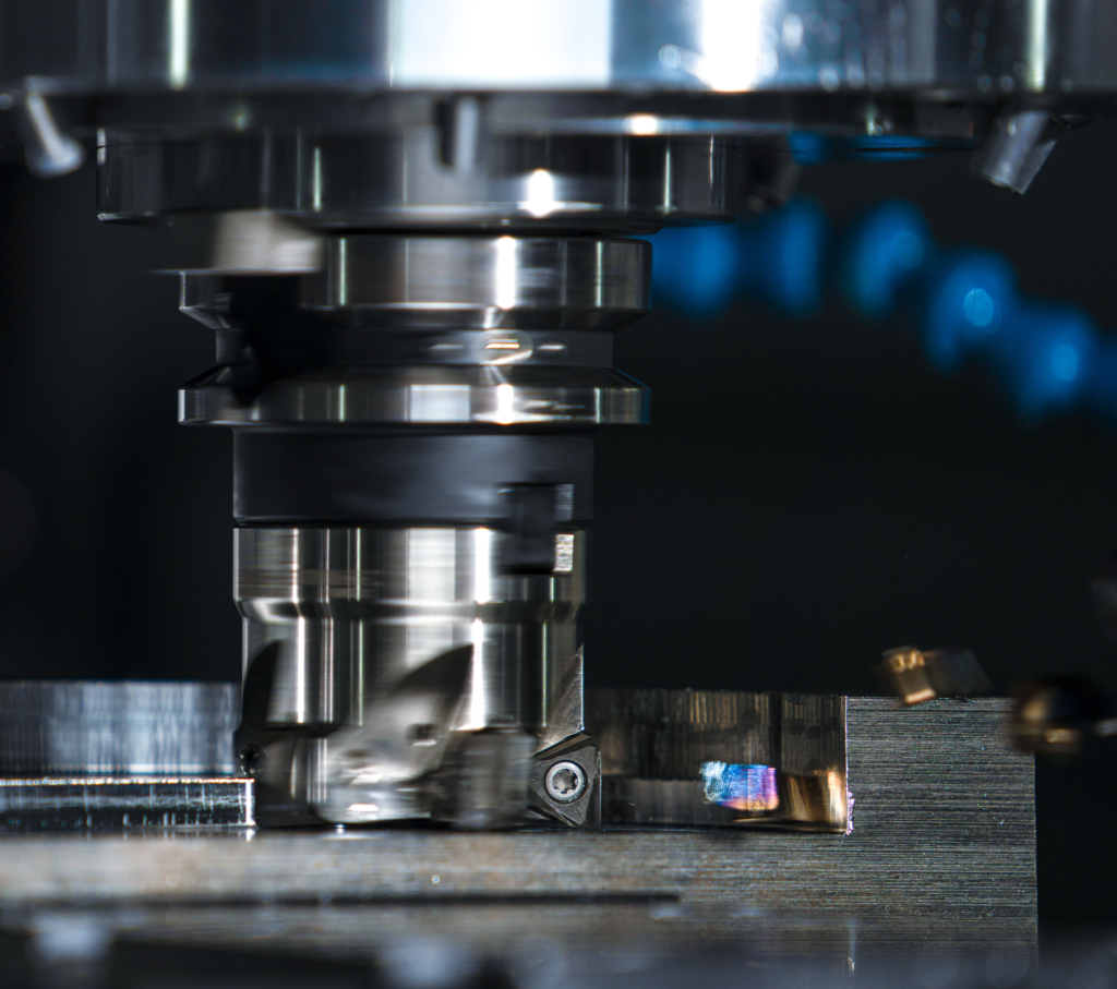
Pocket milling problems rarely begin with spindle speed alone. A tool may run well on an open shoulder, then chatter, recut chips, or chip a corner as soon as it enters a closed cavity. The difference is engagement. Inside a pocket, the cutter has fewer ways to shed heat and chips, and every sharp change in direction can raise the engaged arc without warning.
A dependable process therefore starts with the entry move and toolpath. Open the center so chips have somewhere to go, expand the cavity with controlled radial engagement, and leave a consistent allowance for a separate wall-finishing pass. Linear ramping and helical interpolation are useful entry methods, but their angles and feed rates must match the end mill’s actual capability. Catalog data wins over a generic rule.
Why pockets punish an otherwise good end mill
In side milling, part of the cutter rotation occurs outside the material. Chips can leave the cutting zone, and coolant or air can reach the flutes. A closed pocket is less forgiving. Chips collect around the tool, the cutter repeatedly meets previously cut material, and cornering can turn a moderate width of cut into near-slot engagement.
That combination changes the load on a solid carbide end mill. Carbide is stiff and wear resistant, but it does not tolerate impact from chip recutting or abrupt overload well. The warning signs are familiar: a changing spindle sound, polished chips, smearing on the wall, corner chatter, or small edge chips that quickly grow into a broken flute.
The practical goal is not simply to reduce the cut. It is to keep the cut predictable.
A robust pocket milling sequence
For a simple rectangular or obround cavity, a useful starting sequence is:
- Enter near the center by a predrilled hole, linear ramp, or helical interpolation.
- Open enough space to give chips an escape route.
- Rough outward with a consistent step-over and smooth direction changes.
- Leave a uniform radial and axial stock allowance.
- Finish the wall in a separate pass, then finish the floor if its tolerance or surface requirement justifies it.
Opening the middle first is especially helpful when a conventional offset path would otherwise trap the cutter in a full-width slot. Helical interpolation and linear ramping create the initial opening while spreading entry forces across the machine axes instead of driving the tool straight down.
Where the 40-60% diameter step-over fits
The supplied process notes recommend a radial width of cut, ae, of 0.4D to 0.6D for side milling after the center has been opened. That can be a workable starting band for a rigid setup, moderate axial depth, and a general-purpose end mill when the programmed path avoids heavy corner engagement.
It is not a universal roughing rule. At long axial engagement, on a light machine, or in stainless steel and heat-resistant alloys, a smaller ae with a higher axial depth may produce a steadier load. Dynamic or high-efficiency toolpaths commonly use a much smaller radial engagement because their advantage comes from maintaining a nearly constant engagement angle. The correct value depends on flute geometry, workpiece material, tool overhang, coolant delivery, and the toolmaker’s data.
Cutting situation | Practical starting direction | Why |
Opened pocket, moderate axial depth, rigid setup | ae around 0.4D-0.6D, subject to catalog limits | Productive side cutting when corners are smoothed and chips can leave |
Deep axial cut or long overhang | Reduce ae and use a constant-engagement path | Lowers peak radial force and reduces deflection |
Narrow internal corners | Reduce engagement before the corner; use a larger programmed radius where possible | Prevents a sudden increase in engaged arc |
Final wall pass | Leave uniform stock and use one continuous contour | Avoids witness marks caused by changing allowance |

Toolpath planning: keep cutter engagement boring
The best roughing path is usually the one with the fewest surprises. Repeated straight passes with abrupt 90-degree turns may look efficient on a CAM screen, but the cutter sees a very different load at each corner. A smooth offset, spiral, or adaptive path can keep the radial engagement closer to the programmed target.
Climb milling is the normal first choice on a rigid CNC machine with minimal backlash. It starts with a thicker chip and lets chip thickness fall toward exit. More important for pockets, it should be maintained consistently. Frequent reversals between climb and conventional cutting can change deflection direction and leave visible steps on the wall.
Avoid stop-start wall finishing
When dimensional accuracy matters, do not ask the roughing path to produce the final wall. Leave a consistent radial allowance and finish the contour with a separate continuous pass. If the pocket is deep or the wall is slender, two wall passes can be safer: a semi-finish pass removes most of the remaining stock, and the final pass works with a small, uniform allowance.
This is the useful interpretation of the supplied “two passes assure” guidance. Two passes are not automatically better because the number is two. They help when the first pass creates space and stabilizes stock for the second. Repeating the same overloaded path twice will not fix poor chip evacuation.
Path symptom | Likely cause | Better response |
Chatter begins only in corners | Engagement angle spikes; programmed corner radius is too small | Use arc-based corner smoothing, reduce local feed, or use a smaller tool for rest machining |
Wall shows a step at each depth | Tool deflection changes between levels | Use consistent climb direction, reduce overhang, and add a full-depth finish pass if tool reach permits |
Edge chips after several pockets | Chips are being recut or entry load is excessive | Improve evacuation, reduce ramp feed/angle, and inspect the entry move |
Size varies with direction | Backlash, runout, or changing cutting direction | Check holder/runout and keep the finish contour continuous |

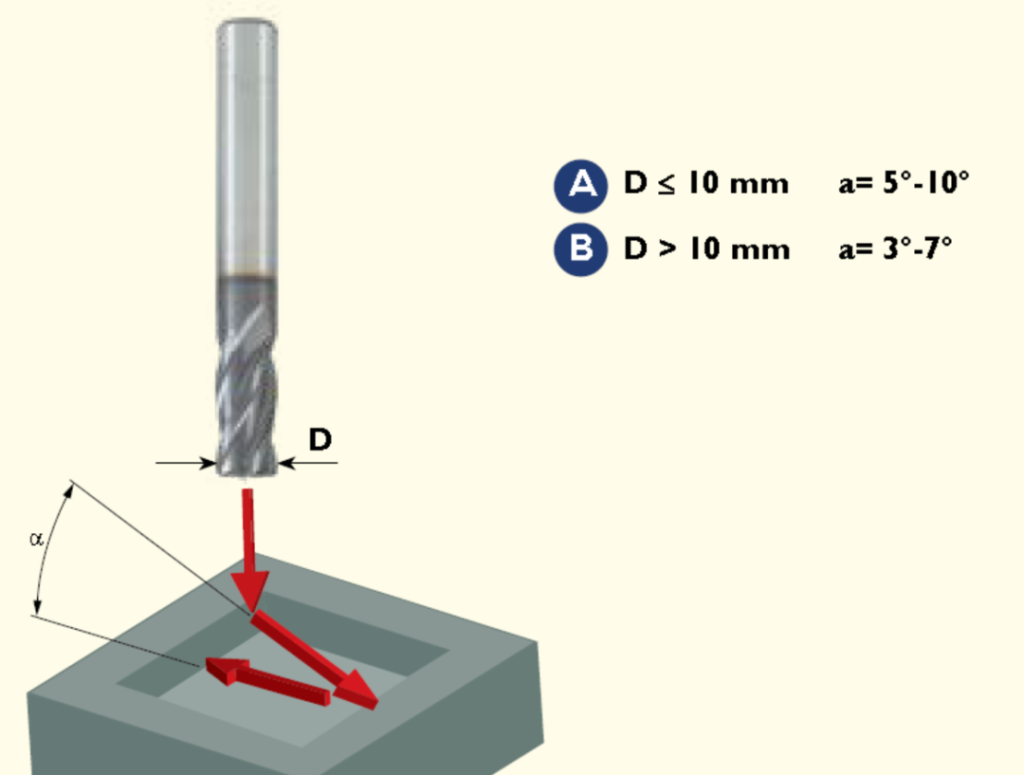
Linear ramping: start with angle, then calculate the required length
A ramp angle is only useful if the available pocket length can accommodate it. For a required vertical drop h and ramp angle alpha, the approximate horizontal travel is:
Ramp length = h / tan(alpha)
For example, dropping 5 mm at 5 degrees requires about 57 mm of horizontal travel. At 3 degrees, the move needs about 95 mm. If the pocket is shorter, the CAM system must zig-zag, reduce the depth per ramp, or use a helix.
The supplied reference gives these starting bands:
- Tool diameter D at or below 10 mm: alpha = 5-10 degrees.
- Tool diameter D above 10 mm: alpha = 3-7 degrees.
Treat those values as application notes for the referenced tool geometry, not as permissions for every solid carbide end mill. Some general-purpose tools are cataloged for only a few degrees of ramping, while specialized high-angle-ramping tools can accept much steeper entry moves. Check the maximum linear and helical ramp angles listed for the exact tool before programming the cut.
Reduce feed during a full-width ramp because the tool is cutting near the center, where surface speed is low and chip space is limited. A conservative commissioning process often begins at 30-50% of the normal side-milling feed, followed by inspection of spindle load, chip shape, sound, and tool condition. That percentage is a starting practice, not a substitute for catalog data.
Helical interpolation: a cleaner entry for many closed pockets
During helical interpolation, the tool follows a circular path while descending in Z. The move avoids a straight plunge and continuously presents an exit direction for the chips. It is often the better choice when the pocket does not provide enough length for a gentle linear ramp.
The hole diameter, tool diameter, and helix pitch must be checked together. In the supplied reference, the suggested hole range is:
Dmin = d + 1 mm
Dmax = 2d – 1 mm
Here, D is the interpolated hole diameter and d is the end mill diameter. The tool-center orbit radius is (D – d) / 2. For a 10 mm end mill, the reference range is therefore 11-19 mm, with tool-center radii from 0.5 to 4.5 mm.
This range should be treated as a geometry-specific heuristic. The minimum orbit must provide clearance for the tool center and chip formation; the maximum orbit depends on how much radial engagement the cutter can tolerate. Always check the manufacturer’s minimum interpolation diameter and maximum ramp angle.
Convert helix pitch to ramp angle
For a helix with tool-center radius r and axial drop per revolution p, the ramp angle is:
alpha = arctan[p / (2 pi r)]
Suppose a 10 mm tool makes a 16 mm hole. The tool-center radius is 3 mm. With a 1 mm axial drop per revolution, the ramp angle is about 3 degrees. This is a useful CAM check: a pitch that looks modest can create a steep angle when the orbit is small.
Internal circular interpolation also requires feed compensation. The programmed feed at the tool center is lower than the desired feed at the cutting edge. Many CAM systems handle this automatically, but the postprocessor output should still be checked against the tool-center path and finished diameter.
Helical entry variable | What to verify | If it is too aggressive |
Hole diameter D | Within the toolmaker’s interpolation range | Excessive radial engagement, rubbing, or no center clearance |
Pitch per revolution p | Produces an allowed ramp angle | High axial load and poor chip formation near the tool center |
Programmed feed | Compensated for tool-center path | Cutting-edge feed becomes higher than intended |
Helix direction | Maintains the intended climb-milling relationship | Higher rubbing or an unstable entry |

Chip evacuation is part of the toolpath
A pocket can fail even when speed, feed, and engagement are reasonable. If the chips remain in the cavity, each flute meets both workpiece material and loose chips. The result is inconsistent load, heat, edge damage, and scratched walls.
Use through-tool coolant when the end mill and holder support it. Otherwise, aim coolant or compressed air so chips move toward the opening instead of deeper into a corner. In deep pockets, consider staged depths that allow evacuation between levels. Watch the chip stream during prove-out. Chips that repeatedly disappear under the cutter are a process warning, not a cosmetic issue.
Tool selection matters too. A three-flute geometry often provides more flute space for aluminum and other high-volume chip applications. Four- and five-flute tools can offer more edge support and feed capacity in steels, but only if the flute space remains adequate for the engagement and depth.
Commission the process without sacrificing the first tool
Start with the end mill manufacturer’s cutting data for the workpiece group, tool diameter, flute count, and operation. Then prove out the pocket at a controlled feed override while watching spindle load and chip evacuation. Stop early if the sound changes sharply at corners or if chips begin to pack.
Check the first pocket before committing to a batch:
- Measure wall size and taper at more than one depth.
- Inspect the floor-wall transition for recutting marks.
- Examine the cutting edges under magnification, especially the corners and center gash.
- Record the actual holder, stickout, coolant method, ae, ap, ramp angle, and helix pitch with the program revision.
Once the path is stable, optimize one variable at a time. Increasing both step-over and feed together may shorten the cycle, but it hides which change caused a load spike or finish problem.

Final takeaway
A solid carbide end mill lasts longer in a pocket when the toolpath controls engagement and makes chip removal easy. Open the center, rough with smooth and predictable radial contact, keep corner loading under control, and finish the wall with a continuous pass. Use ramp-angle and interpolation-diameter rules as starting checks, then confirm them against the exact tool’s catalog data.
HNCarbide can help match flute geometry, coating, diameter, and cutting data to a specific pocket, workpiece material, machine, and production target. Sharing a drawing and the current toolpath is usually more useful than asking for a speed-and-feed number in isolation.




