 Skip to content
Solid Carbide Drill Wear and Application Problems: A Practical Troubleshooting Guide
Table of Contents
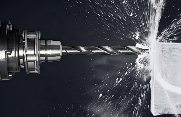
Solid carbide drills are often chosen when a shop needs stable hole size, good productivity, and reliable tool life in CNC drilling. They are stiff, accurate, and capable of running faster than many HSS tools. That same strength also makes them less forgiving. A small runout issue, weak clamping setup, poor coolant delivery, or wrong edge preparation can show up quickly as chipping, rapid flank wear, margin wear, burrs, or rough hole walls.
The most expensive drilling problem is rarely the worn drill itself. It is the chain reaction behind it: scrapped parts, rework, stopped machines, missed delivery dates, and uncertainty about whether the next batch will behave the same way. A practical troubleshooting method helps the shop identify whether the problem is mainly heat, adhesion, mechanical instability, chip evacuation, or tool selection.
This guide uses common solid carbide drill wear patterns as symptoms. It then connects each symptom to likely causes and practical corrective actions. The goal is not to replace a tool supplier’s cutting data. It is to help machinists, production engineers, and tooling buyers ask better questions when a drill starts failing before its expected life.
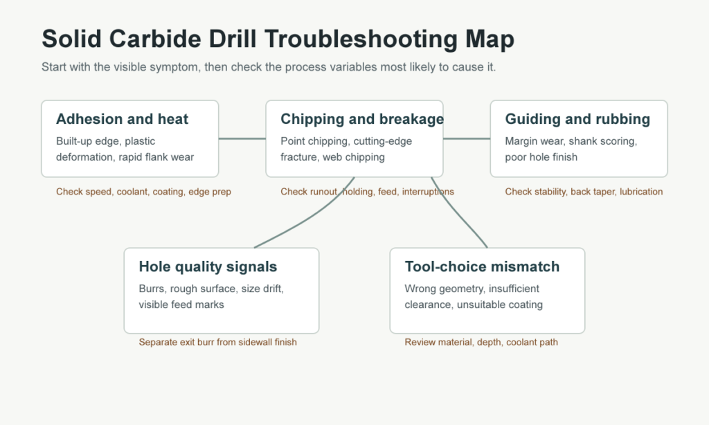
Start With the Symptom, Not the Guess
When a drill fails, it is tempting to change speed, feed, coolant, and tool brand all at once. That can make the problem disappear, but it also hides the real cause. A better approach is to inspect the drill under magnification, check the hole result, and change one variable at a time.
The same visible problem may have more than one cause. Built-up edge can come from low cutting speed, an unsuitable coating, or too much edge honing for the material. Point chipping can come from runout, interrupted cutting, excessive feed, or a weak holder. Poor surface finish may look like a tool-quality issue, but the real cause can be coolant starvation or vibration in the setup.
Use the drill as evidence. Look at the cutting edge, chisel edge, margin, flute, shank, and hole exit. The location of damage usually tells you where the process is losing control.
Built-Up Edge: When Material Welds to the Cutting Edge
Built-up edge appears when workpiece material adheres to the cutting edge instead of leaving cleanly as chips. In drilling, it is common in gummy materials, low-speed conditions, and setups where lubrication is not reaching the cutting zone. Once material sticks to the edge, the drill no longer cuts with its designed geometry. It rubs, tears, and loads unevenly. Hole size and surface finish may drift before the tool finally chips.
Common causes include cutting speed that is too low, excessive edge honing, an uncoated cutting edge in a material prone to adhesion, or insufficient lubrication. Aluminum, low-carbon steel, and some stainless steels can be especially sensitive when chip evacuation is poor.
Corrective actions are usually straightforward. Increase cutting speed within the toolmaker’s safe range, reduce unnecessary cutting-edge hone for softer materials, and select a suitable coating or polished flute design when adhesion is a known risk. Coolant concentration and delivery should also be checked. If the coolant stream does not actually reach the drill point, a higher nominal flow rate may not help.
Point Chipping and Corner Breakage
Point chipping is one of the clearest signs that the drill is seeing mechanical shock. It may appear at the outer corner, at the main cutting edge, or near the intersection between the cutting lip and chisel edge. Solid carbide has excellent hardness and compressive strength, but it does not tolerate bending and impact as well as tougher tool materials.
Typical causes include unstable workholding, excessive radial runout, a worn or inaccurate holder, interrupted cutting, or entering a sloped or uneven surface without proper support. Feed that is too aggressive for the setup can also chip the point, especially in small diameters or deep holes.
Start with the mechanical checks. Measure runout close to the drill tip, inspect the collet or hydraulic chuck, and confirm that the workpiece is not moving. If the holder is questionable, changing cutting parameters will only compensate temporarily. Once the setup is stable, reduce feed slightly and check whether chipping stops. If the operation involves cross holes, cast surfaces, weld seams, or interrupted exits, consider a drill geometry designed for tougher entry and exit conditions.
Severe Flank Wear
Flank wear develops on the relief face behind the cutting edge. A controlled wear land is normal. Severe flank wear, however, increases heat, cutting force, and hole-size variation. The drill begins to rub more than it cuts, and the cutting edge loses the clearance it needs.
The common triggers are excessive cutting speed, too little feed, insufficient relief angle, or a tool that has stayed in production beyond its maximum wear limit. Too little feed can sound counterintuitive, but rubbing at a low chip load can create heat without enough chip thickness to carry that heat away.
Corrective actions include lowering cutting speed, raising feed carefully if the drill is rubbing, and checking whether the tool geometry has enough relief for the material. Shops that run high-volume drilling should define a maximum wear land and replace the drill before the wear pattern becomes unpredictable. Waiting until the tool fails often costs more than replacing it at a controlled interval.
Main Cutting Edge Breakage
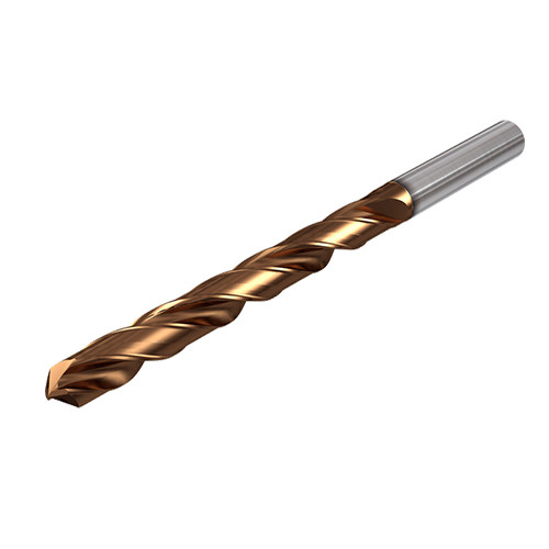
Breakage along the main cutting edge is more serious than gradual wear. It usually means the drill is seeing a combination of load, vibration, or impact that exceeds the edge strength. The cause may be unstable clamping, interrupted cutting, a feed rate that is too high for the condition, or continuing to run after the wear land has grown too wide.
Wrong tool selection can also create this failure. A sharp, free-cutting geometry may be excellent in stable aluminum drilling but too weak for interrupted cuts in alloy steel. A geometry designed for one coolant method may not evacuate chips well in another. In deep holes, chip packing can create sudden torque spikes that break the cutting edge even when the nominal feed and speed look reasonable.
The corrective path is to improve rigidity first, reduce feed if needed, and choose a tool design matched to the material and hole depth. If breakage happens after a predictable number of holes, the tool may simply be running too long. If it happens randomly, the setup or chip flow should be suspected before the drill grade is blamed.
Margin Wear and Shank Scoring
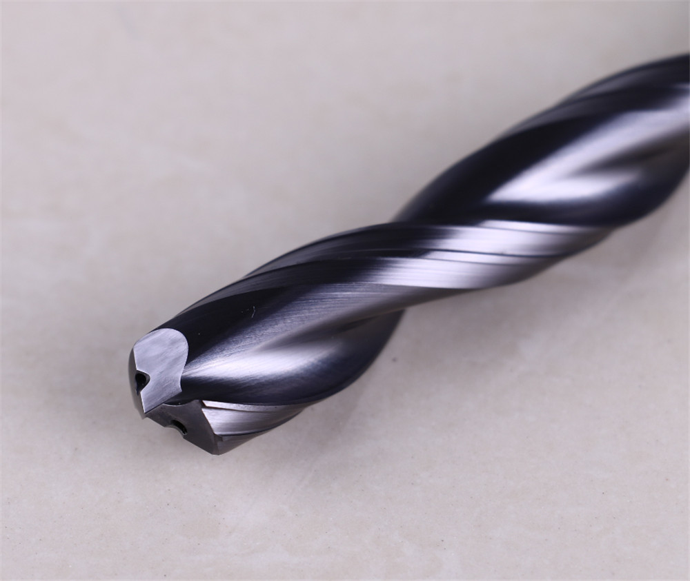
The margin guides the drill inside the hole. When margin wear becomes heavy, the drill can start rubbing the sidewall, generating heat and worsening hole finish. Shank scoring or scratches behind the cutting area usually indicate rubbing, chip packing, poor evacuation, or instability that lets chips drag between the tool and hole wall.
Likely causes include excessive runout, unstable conditions, insufficient back taper, poor coolant lubricity, or using an emulsion that is too thin for a demanding material. Wear-resistant and abrasive materials can make this problem more visible because any trapped chip becomes a cutting particle against the drill body.
Check runout and holder condition. Make sure chips are leaving the hole freely rather than compacting in the flute. For deeper holes, review peck strategy, coolant pressure, and whether through-coolant tooling is required. If the issue is lubrication rather than cooling, a higher-viscosity emulsion or oil may reduce scoring.
Chisel Edge Wear and Chipping
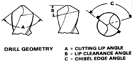
The chisel edge at the center of the drill does not cut as efficiently as the outer cutting lips. It pushes material before the lips form a stable chip. Heavy chisel-edge wear can appear when cutting speed is too low at the outer edge, feed is too high for the point geometry, or the main cutting edge is already worn and forcing more load into the center.
Chisel-edge chipping can also come from insufficient relief angle, too much cutting-edge hone, or a drill geometry that is not suited to the workpiece material. When this area fails, the drill may wander, produce oversized holes, or break suddenly because the point can no longer center itself.
Helpful adjustments include increasing cutting speed when adhesion and rubbing are visible, reducing feed if thrust load is too high, and selecting a geometry with a more suitable point thinning or flute form. If the center fails early in the tool life, do not treat it as normal wear. It is usually a sign that thrust, centering, or edge preparation is wrong.
Plastic Deformation at the Drill Point
Plastic deformation means the cutting edge has softened or moved under heat and pressure. On carbide drills, this is usually linked to excessive heat at the edge. The drill may show rounding, smeared-looking edge damage, or a collapsed corner rather than clean chipping.
The common causes are cutting speed that is too high, insufficient coolant, poor coolant concentration, or an entry/exit condition that concentrates heat at the corner. Incorrect or missing chamfering can also create heavy load at the drill point when a secondary operation is involved.
Lower cutting speed first and improve coolant delivery. Confirm that through-coolant holes are not blocked and that coolant pressure is appropriate for the drill diameter and depth. If the operation uses pilot holes, chamfers, or pre-cast holes, review whether the drill is entering clean material or being forced into an uneven edge.
Poor Surface Finish Inside the Hole
Poor hole finish is often reported as a quality problem, but the root cause may be mechanical, thermal, or chip-related. Visible feed marks, tearing, rough sidewalls, or inconsistent finish from hole to hole can point to runout, vibration, coolant shortage, poor chip evacuation, or a worn margin.
Start by checking whether the drill is cutting on center. Even a good drill can leave a poor finish if runout makes one lip carry most of the load. Then inspect chip shape. Long, stringy, packed chips suggest that the flute and coolant system are not clearing the hole cleanly. Finally, check tool wear. A drill with heavy flank or margin wear may still make holes, but it will no longer produce the finish expected from a fresh carbide tool.
Corrective actions include improving holder accuracy, increasing coolant volume or pressure, adjusting the peck cycle, and changing to a geometry that breaks chips more reliably in the material. For stable production, record the number of holes at which finish begins to decline, not only the point where the drill breaks.
Heavy Burrs at the Hole Exit
Exit burrs are common in drilling, but heavy burrs create extra deburring cost and can damage downstream assembly quality. In carbide drilling, severe burrs at the exit often come from excessive feed, a cutting edge that has become too dull, or an edge preparation that is too heavy for the material.
If the burr grows gradually over the tool life, the cutting edge is probably wearing and pushing material instead of shearing it cleanly. If the burr appears immediately with a new drill, review feed, point geometry, support under the workpiece, and whether the material tends to smear.
Reduce feed near breakthrough if the control strategy allows it. For thin parts or unsupported exits, improve backup support. If the burr problem is material-driven, a sharper edge, more suitable coating, or revised point geometry may be more effective than simply slowing the cycle.
Quick Troubleshooting Table
Symptom | Likely causes | Practical corrective actions |
Built-up edge | Low cutting speed, excessive edge hone, uncoated edge, poor lubrication | Increase speed, reduce hone, choose a coated or polished tool, improve coolant delivery |
Point chipping | Runout, unstable holder, interrupted cut, feed too high | Check clamping and runout, reduce feed, choose a tougher geometry |
Severe flank wear | Speed too high, feed too low, insufficient relief, tool run too long | Lower speed, increase feed if rubbing, use suitable relief angle, replace earlier |
Main cutting edge breakage | Instability, chip packing, interrupted cutting, exceeded wear limit | Improve rigidity, review peck/coolant, reduce feed, change tool before failure |
Margin wear | Runout, poor lubrication, inadequate back taper, abrasive chips | Check runout, improve chip evacuation, use better lubricity, review drill design |
Shank scoring | Chips trapped between tool and hole wall, poor evacuation, vibration | Improve coolant and pecking, check holder stability, consider through-coolant drill |
Chisel edge wear | Feed too high, speed too low, worn cutting lips, unsuitable point geometry | Reduce feed, increase speed where appropriate, use suitable point thinning |
Chisel edge chipping | Relief too small, edge hone too heavy, wrong tool choice | Increase relief, optimize edge prep, select a different drill geometry |
Plastic deformation | Heat too high, coolant shortage, speed too high | Lower speed, increase coolant volume/pressure, check coolant holes and concentration |
Poor surface finish | Runout, vibration, worn margin, poor chip flow | Check runout, improve holding, tune coolant and peck cycle, replace worn drills |
Heavy exit burrs | Feed too high, edge too dull, excessive edge hone | Reduce feed at breakthrough, sharpen/change tool, use sharper geometry |
Material and Application Considerations
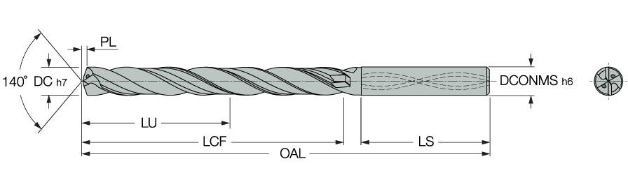
Different materials push the drill toward different failure modes. Aluminum and low-carbon steels often emphasize adhesion and built-up edge. Stainless steel can combine adhesion with heat and work hardening. Cast iron and some powder-metal parts tend to be abrasive, so flank and margin wear may dominate. Titanium and nickel alloys punish heat control and chip evacuation.
Workpiece condition | Main risk for carbide drills | Selection focus |
Aluminum and gummy nonferrous alloys | Built-up edge, chip welding, poor finish | Polished flute, suitable coating or uncoated polished geometry, strong chip evacuation |
Stainless steel | Adhesion, heat, work hardening, exit burrs | Controlled edge prep, coolant access, stable feed, coating for heat and adhesion |
Cast iron | Abrasive flank and margin wear | Wear-resistant grade/coating, rigid setup, dust/chip management |
Alloy steel | Chipping, flank wear, heat at the point | Balanced toughness and wear resistance, accurate holder, correct feed per revolution |
Titanium or heat-resistant alloys | Heat concentration, plastic deformation, chip packing | Coolant pressure, conservative speed, strong geometry, reliable chip breaking |
Cross holes or interrupted exits | Point chipping and cutting-edge breakage | Tougher geometry, lower feed through interruption, strong workholding |
A Controlled Adjustment Method
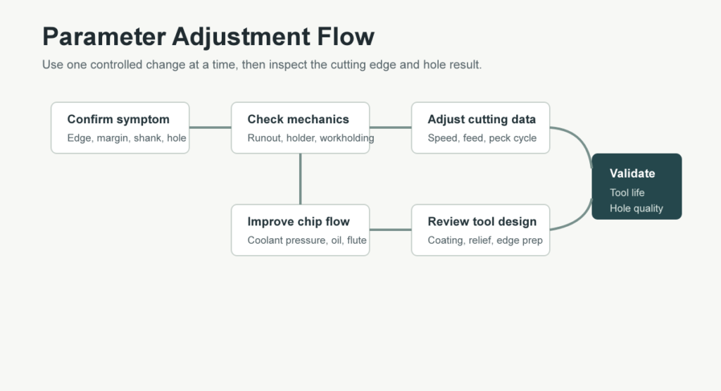
Troubleshooting is easiest when the shop records the starting condition. Note the drill diameter, projection length, holder type, runout, coolant method, material batch, hole depth, speed, feed, and tool life target. Then make one meaningful change and inspect the result.
For example, if built-up edge appears on a stainless component, increasing speed and switching coating at the same time may work, but it does not tell you which change mattered. If a drill chips at the corner, replacing the holder and reducing feed together may stop breakage, but the shop may keep running a slower-than-needed cycle. A simple trial log keeps the fix from becoming guesswork.

Practical Closing Advice
Most solid carbide drill problems come back to five controllable areas: rigidity, runout, cutting data, coolant/chip evacuation, and tool geometry. Start with the visible wear pattern, confirm the mechanical condition, and then adjust speed, feed, coolant, or tool design in a controlled way. That approach gives the shop a repeatable process instead of a collection of one-off fixes.
HNCarbide works with carbide drilling and cutting tool applications where tool life, hole quality, and stable production matter. If your shop is seeing repeated drill chipping, fast flank wear, built-up edge, or burr problems, a structured review of the worn tool and machining conditions is often the quickest way to find the practical fix.





