Milling Machining Guide: From Face Milling to Five-Axis High-Speed Cutting
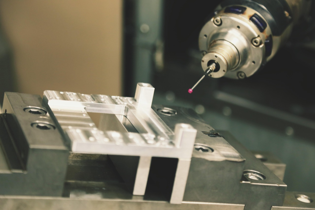
Milling looks straightforward until a shop has to hold a thin wall, finish a deep cavity, or stop a face mill from leaving a step across a broad datum. The cutter rotates, the machine feeds, and metal comes off. Yet every tooth enters and leaves the workpiece, so chip thickness, force, and heat change continuously. Small errors in runout, engagement, tool projection, or chip control repeat several times per revolution.
This guide connects the basic process to the decisions that matter on the shop floor. It covers cutter selection, climb and conventional milling, face and slot operations, high-speed strategies, five-axis positioning, and the defects that raise cost per part. The central idea is simple: productive milling comes from controlled engagement, not from spindle speed alone.
How the milling cut is formed
In most operations, the cutter provides the rotary motion while the machine moves the tool or workpiece along a programmed path. Each tooth removes a chip during part of a revolution. The interrupted cut gives an edge time to cool, but it also subjects the tool and spindle to repeated impact.
Three values define the basic load:
- Cutting speed (vc) is the surface speed at the cutting edge. It depends on cutter diameter and spindle speed.
- Feed per tooth (fz) describes the nominal chip load carried by each edge.
- Axial depth (ap) and radial width (ae) describe how much of the cutter is engaged along and across its axis.
The programmed table feed follows this relationship:
Feed rate (mm/min) = fz (mm/tooth) × tooth count × spindle speed (rpm)
The formula is only the starting point. When radial engagement falls well below 50 percent of tool diameter, chip thinning can make the actual chip thinner than the programmed fz. A shop may need to increase the programmed feed to maintain a productive chip, but only after checking toolmaker data, spindle load, and setup stability.
Choose the cutter around the operation
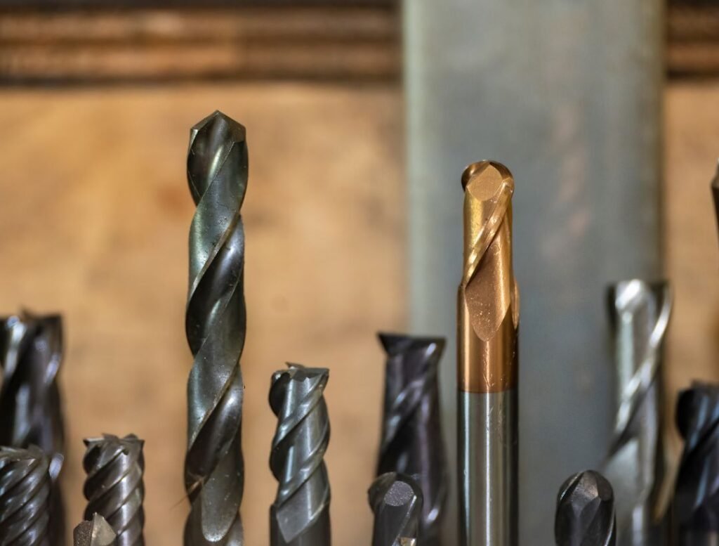
The most expensive cutter is not automatically the most productive one. Start with the surface to be generated, then consider material, access, machine power, holder interface, and expected batch size.
Cutter family | Best-fit work | Selection focus |
Indexable face mill | Broad datum faces and high-volume plane milling | Cutter diameter, lead angle, insert pitch, and wiper geometry |
Square end mill | Slots, profiles, shoulders, and general pockets | Flute count, chip space, usable length, and corner strength |
Corner-radius end mill | Roughing and semi-finishing cavities | Radius large enough to protect the corner without violating the part geometry |
Ball-nose end mill | Freeform surfaces, blends, dies, and molds | Effective cutting diameter, stepover, tilt angle, and surface scallop |
Slotting or T-slot cutter | Narrow grooves, keyways, and undercuts | Neck strength, chip escape, and a prepared access slot |
Thread mill | Large or costly threaded holes | Hole size range, interpolation accuracy, and tool reach |
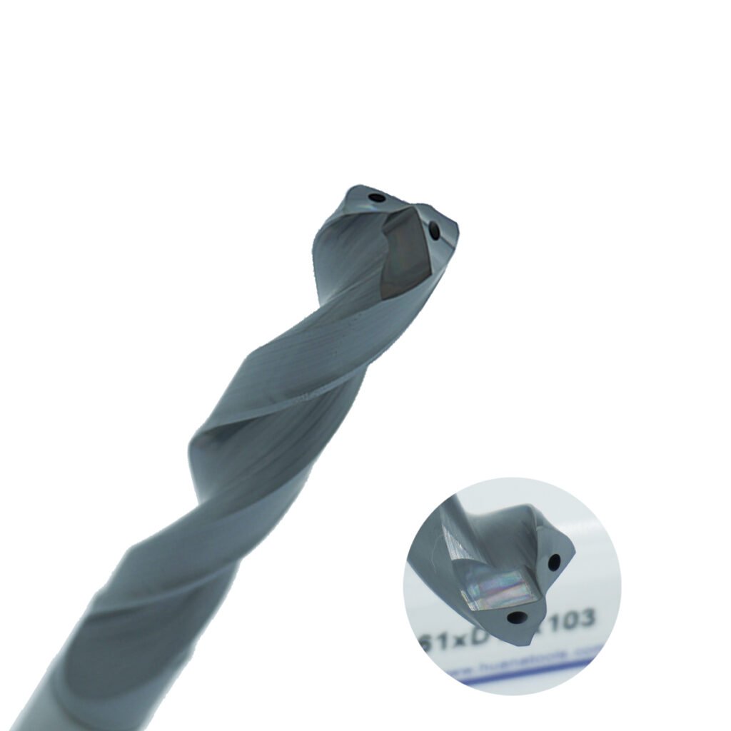
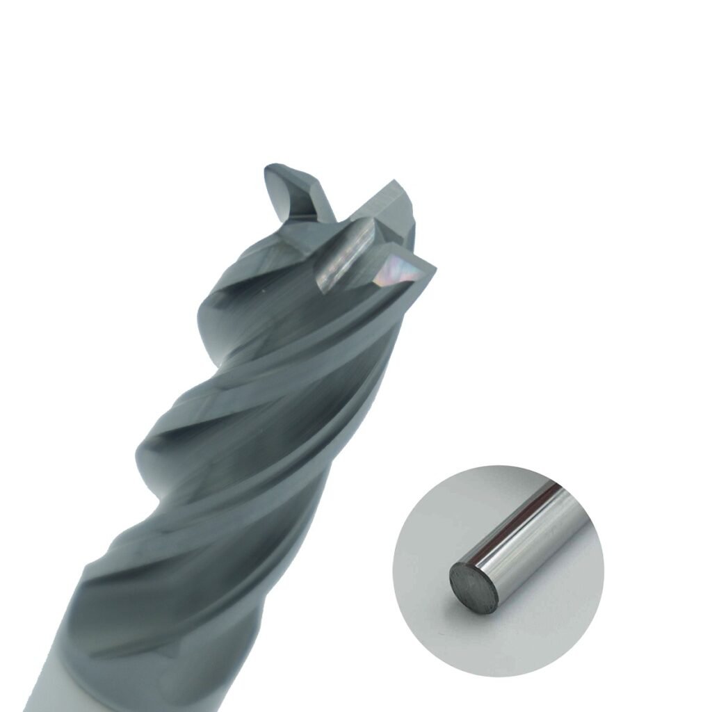
Solid-carbide tools suit small and medium diameters, high spindle speeds, and close-tolerance profiles. Indexable cutters become attractive when diameter, material-removal rate, or edge replacement cost dominates the decision. High-speed steel still has a place in form tools and less rigid work because its toughness and ease of regrinding can outweigh its lower hot hardness.
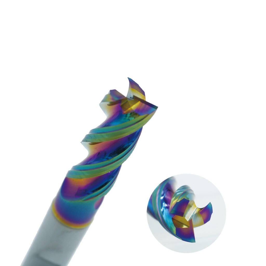
Coating must match the work material and thermal conditions. AlTiN- or AlCrN-family coatings are common choices for steel and hard milling. Aluminum usually needs a sharp, polished flute with low affinity for the work material; an inappropriate coating or a honed edge can encourage built-up edge.
Face milling without steps or torn edges
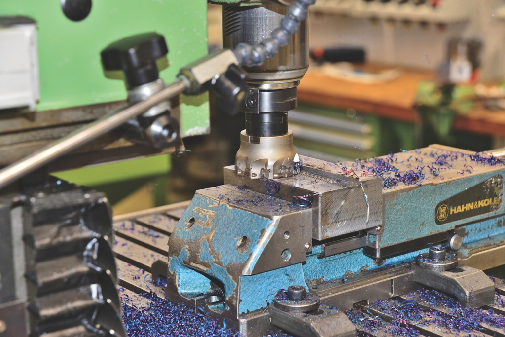
A face mill should normally be wider than the cut so the tool can cover the surface in one pass. The exact diameter and offset affect entry angle, average chip thickness, and the direction of cutting force. Centering a face mill perfectly over the work is not always the best arrangement. A modest offset can produce a more favorable entry and exit, provided the path still covers the full face.
Insert seating matters. One high insert may do most of the finishing work and leave a visible track; contamination beneath an insert can create the same problem. Before changing parameters, clean the pockets, inspect screws and seats, and measure axial runout. On thin or poorly supported parts, a lighter finishing pass may still distort the component if clamping force or heat has already moved it.
Use a coarse-pitch cutter where chip space and low machine power are limiting. A close-pitch cutter can raise productivity in a stable setup because more edges remain in the cut, but it also demands more power and leaves less room for chips.
Climb milling and conventional milling
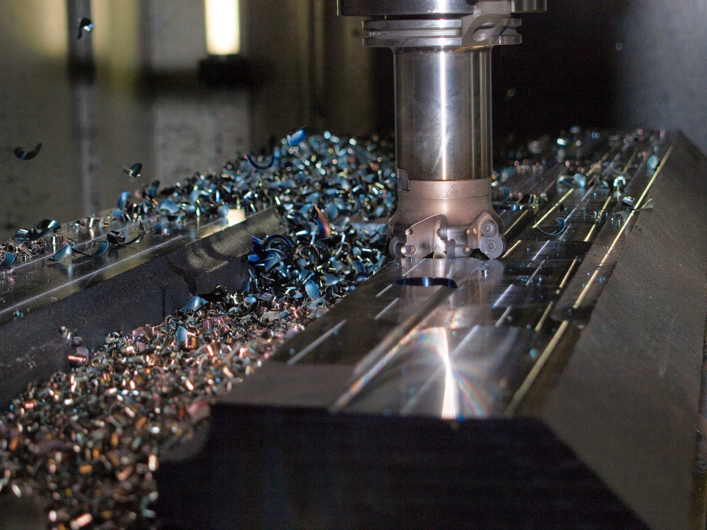
In climb milling, the tooth enters at its greatest chip thickness and exits near zero. On a modern CNC machine with controlled backlash, this usually reduces rubbing and produces a cleaner surface. It is the normal first choice for finished steel, aluminum, and stable profile cuts.
Conventional milling begins with a very thin chip and increases it through the cut. The edge rubs before it starts cutting, which can accelerate wear on work-hardened material. Still, conventional milling may help on a first pass through cast skin or scale because the edge does not strike the hard outer layer at maximum chip thickness. It is also safer on manual equipment where backlash could let a climb cut pull the table forward.
Condition | Preferred starting approach | Reason |
Rigid CNC setup on clean stock | Climb milling | Less rubbing and more predictable finish |
Hard scale or cast skin | Conventional first pass | Gentler initial engagement with the outer layer |
Thin wall or weak fixture | Climb milling with low radial engagement | Reduces side force and deflection risk |
Machine with uncontrolled backlash | Conventional milling | Avoids the cutter pulling the axis into the cut |
Slots, pockets, and shoulders need different engagement
Full-width slotting is one of the hardest jobs for an end mill. Both sides of the cutter are engaged, chip space is restricted, and radial force is high. A feed that works in a 10 percent radial side cut can overload the same tool in a slot.
For a deep pocket, rough with a constant-engagement path where the CAM system and machine can support it. A smaller radial width with a deeper axial cut spreads wear along more of the flute. Leave a consistent allowance, then semi-finish walls and floors before the final pass. The finishing tool should not be asked to correct large, uneven stock left by roughing.
Sharp internal corners create an engagement spike because more of the cutter suddenly enters the material. Use a programmed corner radius larger than the tool radius, a trochoidal transition, or a smaller finishing tool. For T-slots and undercuts, mill the access slot first. The neck of a form cutter is a poor place to absorb an avoidable roughing load.
High-speed milling is a coordinated process
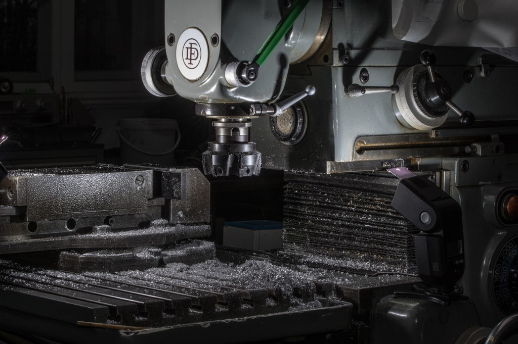
High-speed machining is often reduced to a spindle-speed threshold. That definition misses the process. A useful high-speed strategy combines a balanced tool assembly, low runout, smooth acceleration, controlled radial engagement, and toolpaths that avoid sudden changes in cutter load.
In hardened-steel finishing, the radial width may be a fraction of a millimeter. In aluminum roughing, the spindle and feed can be much higher, but chip evacuation and machine acceleration may become the real limits. In both cases, the process fails when corners, lead-ins, or re-entry moves create an engagement spike.
Keep the tool assembly short. Confirm that the holder, collet, pull stud, and cutter are rated for the intended speed. For small finishing tools, a few micrometers of runout can make one flute carry most of the load. Shrink-fit and hydraulic holders can help, but only if the complete assembly is clean, balanced, and measured.
Coolant strategy depends on material and operation. Aluminum often benefits from strong chip flushing and lubrication. In some hardened-steel applications, a stable dry or air-blast process is safer than intermittent flood coolant that repeatedly heats and quenches the cutting edge. Follow the cutter supplier’s recommendation rather than switching coolant on and off during a cut.
When five-axis milling earns its cost
Five-axis machining adds two rotary axes to the three linear axes. The machine may use a tilting table, a swiveling head, or one of each. The value is not movement for its own sake. Rotary positioning keeps the cutter at a useful angle, shortens the required tool, and reaches surfaces that would otherwise need another setup.
For a mold or impeller, tilting a ball-nose cutter moves contact away from the tool center, where surface speed approaches zero. A shorter tool improves stiffness in a deep cavity. For prismatic parts, 3+2 positional machining can finish several faces in one clamping without the programming burden of continuous simultaneous motion.
Five-axis work also adds failure modes. The postprocessor must match the machine kinematics. Rotary-axis center errors affect tool-tip position, and a small tool-length or fixture error can become large as the axes rotate. Before cutting an expensive part, verify the kinematic calibration, tool-center-point control, safe retracts, holder clearance, and the posted program in simulation.
Five-axis capability does not remove the need for a sound three-axis process. If the tool chatters because of excess projection or unstable engagement, tilting the head may only move the problem.
Practical starting windows and trial-cut discipline
Generic data should never override the cutter manufacturer’s recommendation. The broad windows below are useful for planning and comparison, not for releasing a production program.
Application | Typical cutter | Indicative cutting speed | What to watch first |
Carbon-steel face milling | Coated indexable face mill | 150-250 m/min | Insert seating, spindle load, and edge condition |
Cast-iron face milling | Coated indexable face mill | 150-220 m/min | Abrasive wear and unstable scale engagement |
Aluminum end milling | Polished solid carbide | 250-600 m/min | Built-up edge, chip packing, and machine acceleration |
General-steel end milling | Coated solid carbide | 70-160 m/min | Runout, radial engagement, and tool projection |
Hardened-steel finishing | Fine-grain coated carbide | 80-180 m/min | Smooth toolpath, light engagement, and thermal stability |
Start with a supervised cut. Record material grade and hardness, cutter and holder identifiers, projection, measured runout, coolant method, spindle load, sound, chip form, and edge condition. A parameter sheet without setup information is difficult to reproduce.
Troubleshoot the cutting system, not one number
Symptom | Likely mechanism | First checks and corrections |
Chatter or repeating waves | Low dynamic stiffness, long projection, engagement spike | Shorten the assembly, strengthen clamping, reduce radial width, and vary spindle speed away from resonance |
Tapered wall or oversize pocket | Tool deflection or unstable stock allowance | Separate rough and finish passes, lower side load, and finish at a consistent allowance |
Poor face finish | Insert runout, built-up edge, weak support | Clean and measure insert seats, check grade and coolant, and inspect part support |
Rapid edge wear | Excess speed, abrasive material, thermal cracking | Review grade and coating, reduce speed, and stabilize coolant application |
Chip welding or recutting | Inadequate flute space or evacuation | Use fewer flutes where appropriate, increase air or coolant delivery, and revise the path |
Five-axis mismatch or gouge | Calibration, tool-length, fixture, or post error | Recalibrate rotary centers, verify offsets, simulate the posted code, and check holder clearance |
Changing every value at once hides the cause. Make one controlled adjustment, inspect the edge and part, and record the result. If lowering feed appears to help for a few minutes but the edge begins rubbing, the apparent cure may shorten tool life.
A buyer checklist for milling tools
Before standardizing a cutter family, ask the supplier to address the actual production envelope:
- Which material grades and hardness ranges will the tool encounter?
- Is the operation dominated by roughing, finishing, slotting, or mixed work?
- What spindle interface, speed, power, and coolant delivery are available?
- What projection and holder type will the real part require?
- How will tool life end: flank wear, chipping, finish loss, burr growth, or dimensional drift?
- Can replacement tools and inserts be supplied with consistent geometry and lead time?
A useful trial compares cost per conforming part, not only minutes of cut or unit tool price. Include setup time, offset changes, scrap risk, and the labor needed to recover an unstable process.

Final takeaway
Face mills, end mills, ball-nose tools, and form cutters solve different problems. Choose among them by the surface, engagement, access, and machine limits. Use climb milling on capable CNC equipment, plan chip escape before deep slotting, and treat high-speed machining as a system of tool, holder, path, and machine dynamics.
Five-axis machining extends that system by controlling tool orientation. It can shorten tools, reduce setups, and improve access, but it raises the importance of calibration, simulation, and postprocessor accuracy. HNCarbide can support buyers in matching carbide grade, flute design, edge preparation, and tool dimensions to the material and operating conditions behind the drawing.