
How to Choose Turning Inserts: Shape, Chipbreaker, Grade, Nose Radius, and Troubleshooting
Table of Contents
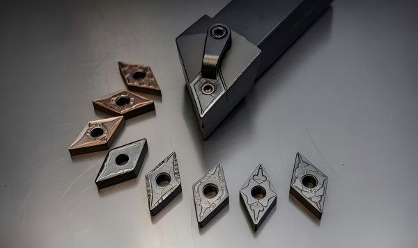
A turning insert is a small part, but it can decide whether a lathe job runs smoothly or turns into a pile of rejected parts, chipped edges, and rushed setup changes. Shops often notice the insert only when something goes wrong: chips wrap around the workpiece, the surface finish turns cloudy, a new coated insert breaks within minutes, or a roughing job eats corners faster than expected.
Most of those problems are not solved by buying the most expensive insert in the catalog. They are solved by matching the insert to the cut. Shape, chipbreaker, carbide grade, coating, nose radius, and insert size all change how the cutting edge handles force, heat, chip flow, vibration, and surface finish.
This guide turns the usual catalog choices into a practical selection process for CNC machinists, production managers, and tooling buyers. The goal is simple: pick an insert that can do the job, hold quality, and keep cost per part under control.
Start With the Cut, Not the Insert Code
Insert codes matter, but they should come after the machining condition. A CNMG, DNMG, VNMG, or WNMG designation tells you the basic shape and size. It does not tell you whether the job is stable, whether the material is gummy, whether the stock is interrupted, or whether the machine has enough rigidity for a larger nose radius.
Before choosing an insert, define five things:
- Workpiece material and hardness
- Operation type, such as roughing, semi-finishing, finishing, profiling, boring, grooving, or threading
- Cutting condition, especially continuous versus interrupted cutting
- Machine, holder, and workholding rigidity
- Required surface finish, tolerance, and tool-life target
That may sound basic, but it prevents many common mistakes. An insert that works well on continuous steel finishing may fail badly on scaled stock with interrupted entry. A sharp insert for aluminum can cut stainless at first, then build up material on the edge and ruin the finish. A larger nose radius may improve theoretical roughness, but it can also push a flexible shaft into chatter.
Insert Shape: Strength, Accessibility, and Economy
Insert shape controls edge strength, indexing economy, accessibility, and the type of turning operation the tool can handle. In general, a larger included angle gives a stronger cutting edge. A smaller included angle gives better access for profiling and machining close to shoulders, but the cutting edge is weaker.
This is why roughing operations often favor stronger shapes, while profiling and finishing may use sharper, more accessible shapes. The most economical insert is not always the cheapest per piece. It is the insert that gives enough usable edges, survives the load, and avoids scrap.
Insert shape | Common use | Strength and tradeoff |
Round | Heavy roughing, high edge strength, profiling with smooth engagement | Strongest edge, but higher cutting force and less access to tight profiles |
Square | Roughing and interrupted cuts where strength matters | Stronger than triangular shapes, good edge economy, limited approach flexibility |
Trigon / W-style | General turning and face turning | Good edge count and balanced strength, common in production turning |
Diamond 80 degree | General external and facing work | Widely used balance of strength and accessibility |
Diamond 55 degree | Profiling, finishing, shoulder access | Better clearance but weaker cutting edge than 80 degree shapes |
Triangle | Light to medium turning, economical indexing | Good edge economy, but lower strength under heavy load |
For a heavy interrupted cut, choose the largest practical nose angle and a strong insert shape. For a slender profile or tight shoulder, you may need a narrower diamond shape, but compensate with a suitable grade, edge preparation, and conservative feed.
Chipbreaker: The Part of Selection Shops Often Underestimate
Chip control is not a nice extra in turning. It affects operator safety, surface finish, tool life, cycle reliability, and automation. If chips wrap around the workpiece or toolholder, the insert may be technically cutting, but the process is not under control.
Chipbreakers are usually grouped by operation: finishing, medium machining, and roughing. A finishing chipbreaker uses a small groove and sharper geometry so thin chips can curl and break at low feed and shallow depth of cut. A roughing chipbreaker has a wider, stronger form that can handle thick chips and higher feed. A medium chipbreaker covers the range between them.
The chipbreaker must work inside its feed and depth-of-cut window. If the depth of cut is too shallow for a roughing chipbreaker, chips may not curl properly. If feed is too low, the chip can stay too thin and stringy. If feed is too high for a finishing geometry, the edge may overload or chip.
Stainless steel shows this clearly. Austenitic stainless tends to produce tough, continuous chips. A sharp, positive, free-cutting chipbreaker can reduce cutting force, but the chip still needs enough thickness to break. In many stainless jobs, a small increase in feed improves chip control better than simply slowing the machine down.
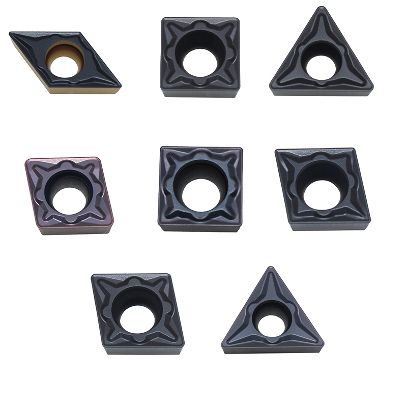
Carbide Grade and Coating: Match the Material and the Shock Level
Carbide inserts are commonly selected by ISO material groups. The exact naming varies by manufacturer, but the logic is familiar:
Workpiece material | ISO direction | Selection focus |
Steel | P group | Balance crater wear resistance, flank wear resistance, and edge strength |
Stainless steel | M group | Toughness, sharp geometry, chip control, and resistance to built-up edge |
Cast iron | K group | Abrasion resistance, edge stability, and dry or controlled coolant use |
Non-ferrous metals | N group | Sharp polished edges, low adhesion, and chip evacuation |
Heat-resistant alloys | S group | Heat control, notch resistance, and tough cutting edge |
Hardened steel | H group | Hot hardness, edge preparation, and sometimes CBN or ceramic instead of carbide |
Harder, more wear-resistant grades usually perform well in stable continuous cutting. Tougher grades handle impact, interrupted cuts, rough stock, vibration, and heavy feed better. Coatings add another layer. CVD coatings often suit productive steel and cast iron turning where heat resistance matters. PVD coatings often keep a sharper edge and are useful for stainless steel, finishing, and less stable cuts.
One common shop-floor trap is blaming a new coated insert for breaking immediately. Sometimes the insert is defective, but more often the grade or coating style does not match the shock level. A thick CVD-coated insert can perform very well in stable continuous steel turning. Put it into a harsh interrupted cut with poor seating or too much feed at entry, and the coating or edge may chip before it reaches normal wear life.
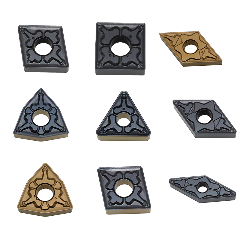
Nose Radius: Finish, Strength, and Rigidity
Nose radius affects surface finish, edge strength, cutting force, and the minimum useful depth of cut. A larger radius can produce a smoother theoretical finish at the same feed and provides more edge strength. It also raises radial cutting force. If the machine, holder, or workpiece lacks rigidity, that extra force may create chatter and make the finish worse, not better.
A smaller radius cuts with less force and works better for slender parts, light finishing, small depths of cut, and tight shoulder access. It is also less forgiving in heavy roughing because the edge has less support.
As a practical rule, do not let the planned depth of cut become too small compared with the nose radius. When the insert only rubs along a large radius instead of taking a stable chip, cutting force, heat, and poor finish can follow. For finishing, a wiper insert can be a good option when the shop wants better surface finish without slowing feed as much, but it still needs a rigid setup and correct orientation.
Insert Size and Thickness: Do Not Undersize the Edge
Insert size is partly a holder question, but it is also a load question. Heavy roughing, interrupted cuts, large depths of cut, and high feed need enough insert thickness and seating support. A small insert can work beautifully in a light finishing pass and fail quickly in roughing simply because the edge and clamping system are undersized for the load.
Check the toolholder pocket, shim, clamp screw, and insert seating surface before assuming the insert grade is the problem. A loose screw, damaged pocket, worn shim, or chip trapped under the insert can cause repeated edge failure. In production, this kind of mechanical issue can look like a tooling-quality problem even when the insert is fine.
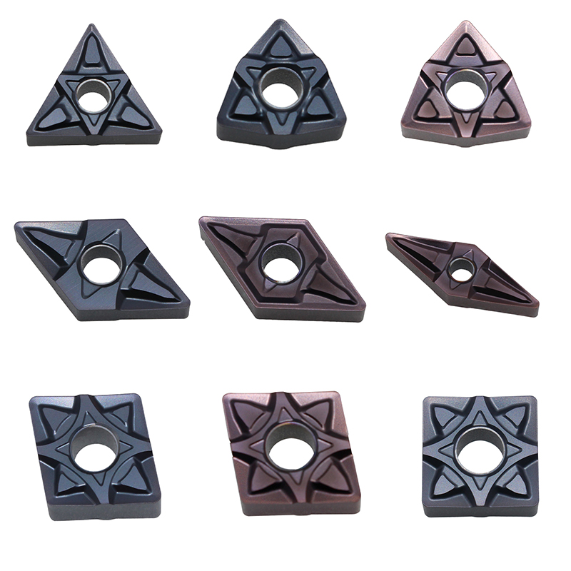
Common Turning Insert Problems and Practical Fixes
Insert failure is not random. The damaged edge usually tells you where to look first. Do not change grade, speed, feed, coolant, and chipbreaker all at once. Change one major variable, then compare the result.
Problem seen in turning | Likely cause | Practical correction |
Edge chipping | Feed too high, interrupted cut, hard inclusions, weak edge, poor clamping, vibration | Reduce feed at entry, use tougher grade, choose stronger shape or edge prep, inspect holder seating |
Rapid flank wear | Cutting speed too high, abrasive material, grade not wear-resistant enough | Reduce speed, move to more wear-resistant grade or coating, check coolant direction |
Crater wear | High heat and heavy chip contact on rake face | Reduce speed, improve coolant where suitable, use grade/coating with better hot wear resistance |
Built-up edge | Speed too low, sticky material, dull edge, poor lubrication | Increase speed within safe range, use sharper positive geometry, improve coolant or lubrication |
Thermal cracking | Repeated heating and cooling, interrupted cutting, inconsistent coolant | Stabilize coolant flow, consider dry or consistent wet strategy, reduce thermal shock |
Stringy chips | Wrong chipbreaker range, feed too low, depth of cut too shallow | Use correct chipbreaker, raise feed carefully, adjust depth of cut |
Poor surface finish | Worn edge, wrong nose radius, excessive feed, chatter, built-up edge | Inspect edge, adjust feed/radius, improve rigidity, consider wiper geometry |
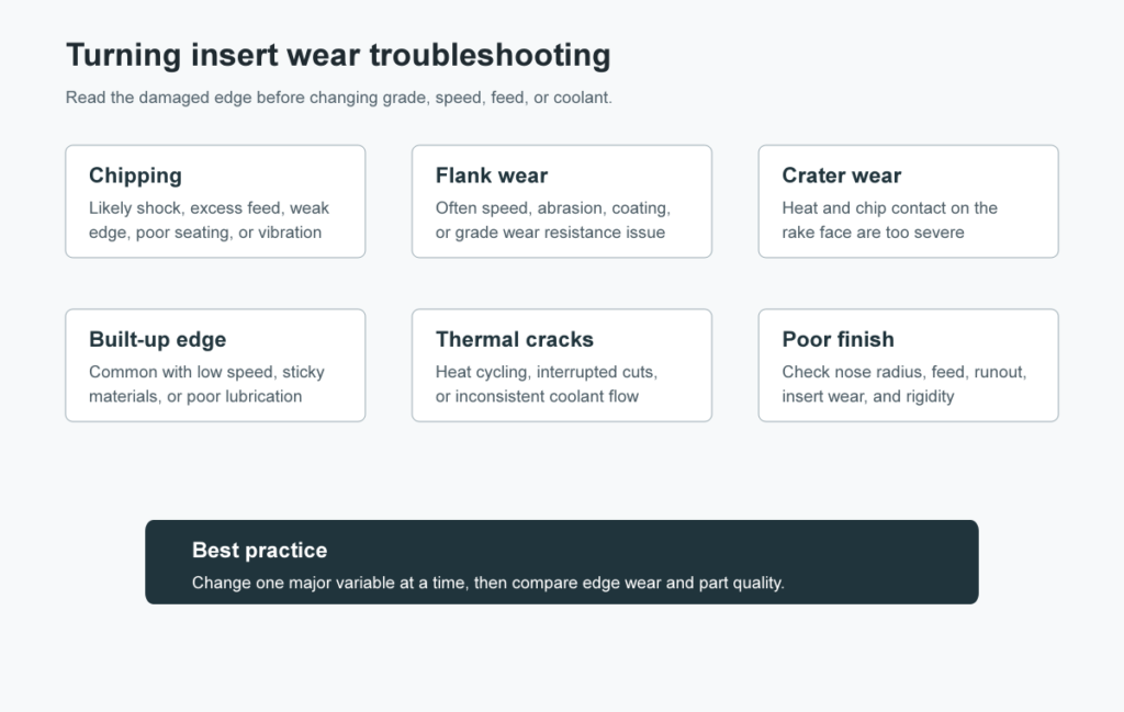
Chipping: Look for Shock Before Blaming the Grade
Chipping is one of the most frustrating failures because it can appear suddenly. The likely causes are mechanical: interrupted cuts, high feed, poor entry angle, hard spots, vibration, or weak insert seating. A very hard grade may chip because it lacks toughness for the impact. A sharp finishing geometry may chip because the edge is too delicate for the load.
Start with the setup. Confirm the insert sits flat in the pocket. Check the clamp screw and shim. Look for chips under the insert. Reduce tool overhang where possible. If the workpiece is long or thin, support it better before making aggressive parameter changes.
Then adjust the cutting edge. Move toward a tougher grade, a stronger chipbreaker, a larger included-angle shape, or a stronger edge hone. Reducing feed at entry can help with interrupted surfaces. For roughing, avoid using a finishing insert simply because it is available on the shelf.
Flank Wear and Crater Wear: Heat, Speed, and Grade
Flank wear usually points toward abrasion, cutting speed, workpiece hardness, or insufficient wear resistance. If the wear land grows evenly and predictably, the process may simply need a more wear-resistant grade or a lower speed. If flank wear accelerates near scale, casting skin, or hard inclusions, the material surface may be driving the problem.
Crater wear forms on the rake face where hot chips slide over the insert. It weakens support behind the edge, so a crater-worn insert may later chip or fail suddenly. Lowering cutting speed, improving chip flow, selecting a coating with better heat resistance, or changing chipbreaker geometry can reduce crater wear.
Coolant helps only when it reaches the right place consistently. A weak stream that misses the cutting zone may make the operator feel better without helping the insert much. In interrupted turning, inconsistent coolant can also increase thermal shock. The choice between wet, dry, and high-pressure coolant should match the material, operation, and machine capability.
Built-Up Edge and Stainless Steel Chip Control
Built-up edge is common when machining sticky materials at low speed or with a geometry that does not shear cleanly. Material welds to the cutting edge, then breaks away and damages the surface or edge. Stainless steel and soft low-carbon steel can both show this problem.
For stainless steel, chip control and heat control have to be handled together. Use a chipbreaker intended for stainless or difficult materials, often with a sharper positive geometry. Keep the feed high enough to make a chip the chipbreaker can actually break. Too low a feed can create a thin ribbon that wraps around the part.
If the finish is poor and the chip looks smeared rather than cut, do not only blame the insert coating. Check speed, feed, edge sharpness, coolant concentration, and whether the insert is rubbing because the depth of cut is too light.
Surface Finish: Nose Radius Is Only Part of the Answer
When surface roughness fails inspection, many shops first look at nose radius. That is reasonable, but it is incomplete. Feed rate, tool wear, insert runout, machine rigidity, chatter, built-up edge, and workpiece support all affect finish.
A larger nose radius can improve theoretical roughness, but it increases cutting force. If the part is slender or the boring bar is long, a smaller radius may produce a better real finish because it cuts with less pressure. Wiper inserts can improve finish at a given feed, but they are not a cure for a flexible setup or a worn toolholder.
The best finish usually comes from a stable combination: correct nose radius, controlled feed, sharp enough edge, good chip evacuation, and a holder that keeps the insert seated consistently.
A Practical Selection Checklist
Selection step | What to confirm | Why it matters |
Material | Steel, stainless, cast iron, aluminum, hardened steel, heat-resistant alloy | Drives carbide grade, coating, edge sharpness, and coolant strategy |
Operation | Roughing, medium turning, finishing, profiling, boring, grooving, threading | Determines chipbreaker, edge strength, and insert shape |
Cutting condition | Continuous, interrupted, scaled, forged, cast, welded, or unstable | Determines toughness requirement and risk of chipping |
Chipbreaker | Feed and depth-of-cut window | Poor chip control can stop automation and damage the finish |
Nose radius | Finish target, rigidity, and depth of cut | Too large can chatter; too small may lack strength |
Holder condition | Pocket, shim, clamp screw, overhang, coolant delivery | Mechanical issues can destroy a good insert |
Trial result | Wear mark, chip shape, sound, part size, surface finish | Confirms whether the selection works in the real machine |

Conclusion
Good turning insert selection is a matching job. Match the grade to the workpiece material. Match the chipbreaker to the feed and depth of cut. Match the insert shape to the load and access requirement. Match the nose radius to finish goals and machine rigidity. When a problem appears, read the insert before changing everything.
The small insert at the cutting edge carries the cost of the whole setup: machine time, operator attention, part quality, and delivery schedule. Choosing it carefully is one of the simplest ways to improve turning stability.
HNCarbide supplies carbide cutting tools for practical CNC machining applications, including turning, milling, drilling, and custom tooling needs. If your current turning inserts are wearing fast, chipping early, or failing to control chips, start with the real cutting condition. The right insert choice becomes much clearer from there.




