
How to Choose Turning Insert Nose Radius for CNC Lathe Work
Table of Contents
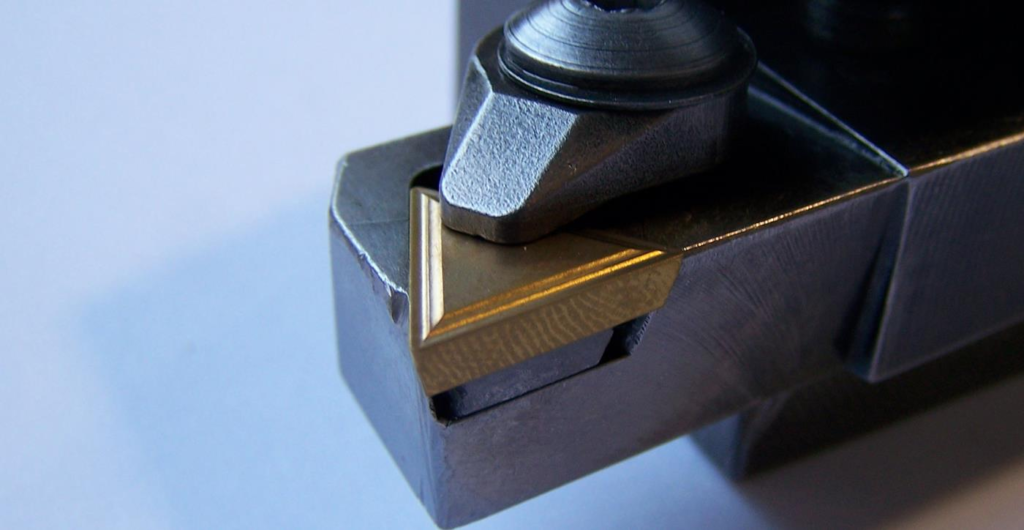
Corner radius looks like a small detail on a turning insert drawing, but it often decides whether a CNC lathe job runs quietly or turns into chatter, poor finish, size drift, or short tool life. Many shops learn this the hard way. A larger radius gives a stronger corner and better theoretical roughness, yet the same insert can push a thin shaft away from the tool. A small radius can hold a sharp profile, but it may wear fast if it is asked to rough a scaled forging.
The right choice is not “large for strength” or “small for accuracy.” It is a match between the operation, depth of cut, feed, workpiece material, machine rigidity, holder overhang, and the corner geometry on the drawing. For production managers and tooling buyers, the corner radius also affects repeatability, cycle reliability, and cost per part.
This guide explains how corner radius works in CNC turning and how to select it for roughing, semi-finishing, finishing, profiling, and weak-rigidity setups.
What Corner Radius Does in a Turning Cut
The corner radius is the rounded cutting edge between the insert’s side cutting edge and end cutting edge. In many insert drawings and ordering tables it appears as RE, and it is one of the first geometry values engineers check when matching a turning insert to a CNC lathe operation. Common ISO turning inserts may use radii such as 0.2 mm, 0.4 mm, 0.8 mm, 1.2 mm, 1.6 mm, or larger, depending on insert size and application.
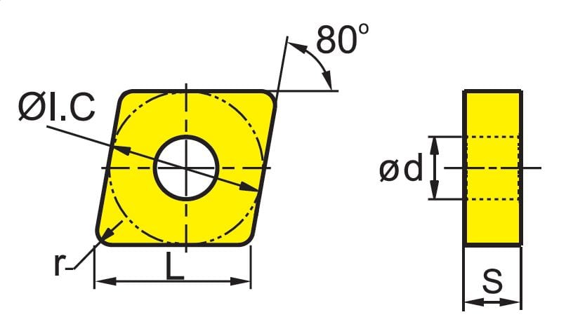
Its first job is to spread cutting force and heat. A sharp theoretical corner would concentrate load in a very small area. A radius lets more edge length participate in the cut, reducing unit load at the corner and improving resistance to chipping. This is why larger corner radii are common in rough turning, interrupted cuts, and heavy stock removal.
Its second job is to shape the feed marks left on the workpiece. In turning, the rounded corner sweeps a helical path over the rotating part. With the same feed per revolution, a larger radius leaves a lower theoretical scallop height. This is the reason many machinists reach for a larger radius when surface finish is poor.
But there is a catch. The radius also changes the direction of cutting forces. As more of the rounded edge takes over the cut, radial force increases. Radial force pushes the tool and workpiece away from each other. On a rigid machine with a short holder and solid workholding, that may be manageable. On a slender shaft, thin-wall tube, small boring bar, or long overhang, it can be the start of chatter.
The Core Rule: Depth of Cut Should Normally Be at Least the Corner Radius
One of the most useful shop-floor rules is simple: the radial depth of cut, ap, should normally be equal to or larger than the corner radius, R.
When ap >= R, the straight part of the cutting edge carries much of the load. The force direction is more predictable, chip formation is cleaner, and the corner radius works as a transition and finishing edge.
When ap < R, the cut is carried mainly by a small arc on the rounded corner. The insert is no longer shearing as cleanly along the main edge. It starts to rub and plow more, radial force rises, and the process becomes more sensitive to rigidity. In stainless steel, nickel alloys, and other work-hardening materials, this can harden the surface ahead of the next pass. In lower-carbon steels, it can leave a torn or cloudy finish even though the radius is theoretically large enough for a smooth surface.
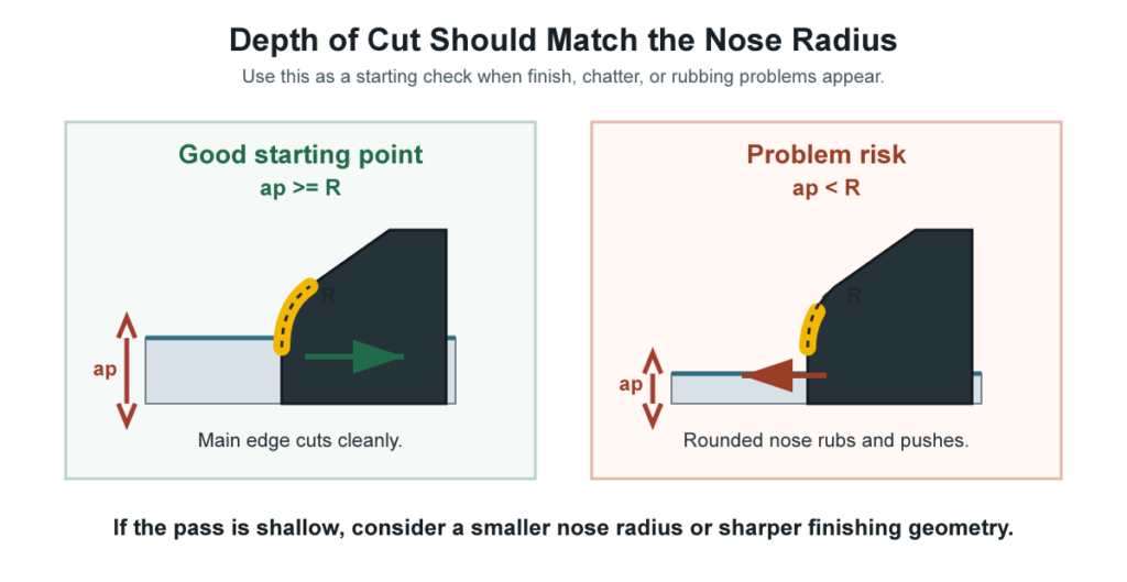
This rule does not mean a 0.8 mm radius can never take a 0.2 mm finishing pass. Many finishing operations do exactly that under stable conditions, especially with wiper geometry or a controlled finishing chipbreaker. It means the machinist should understand the tradeoff: once the depth of cut falls below the radius, the cut becomes more dependent on edge sharpness, feed, chipbreaker design, and system rigidity.
Large Corner Radius Inserts: Strong, Productive, and Rigidity-Hungry
A large corner radius, often 1.6 mm or above in general turning, is usually chosen for roughing, heavy stock removal, interrupted cuts, cast skin, forged scale, and rough surfaces where edge strength matters. The thicker corner resists chipping, spreads heat over a longer cutting edge, and can support higher feed.
This is useful when the setup is built for it. A heavy CNC lathe, short tool overhang, strong clamping, stable chucking, and a solid workpiece can take advantage of the larger radius. In these conditions, a larger corner can reduce sudden edge failure and make tool life more predictable.
The limitation is force. A large radius increases radial load, especially when the depth of cut is shallow relative to the radius. The tool may push the workpiece away, the holder may deflect, or the spindle/workholding system may begin to vibrate. The symptoms are familiar: repeating chatter marks, taper, poor roundness, insert micro-chipping, and a finish that gets worse even after reducing speed.
Use a larger radius when the job needs high feed, strong edge support, and impact resistance. Avoid it as a default fix for poor finish on flexible parts. If chatter appears, reducing corner radius may solve the problem faster than changing speed several times.
Medium Corner Radius: The Everyday Production Choice
For many CNC turning jobs, 0.8 mm and 1.2 mm radii are the practical middle ground. They are common in semi-finishing, medium roughing, and general external turning because they balance edge strength, surface finish, and cutting force.
A 0.8 mm radius is often a safe first choice for general steel turning when the workpiece is reasonably rigid and the part drawing does not restrict the corner. It can carry moderate feed, produce a good finish with the right chipbreaker, and avoid the aggressive radial force of a much larger radius.
A 1.2 mm radius moves closer to roughing territory. It gives more edge strength and better theoretical feed-mark control, but it asks more from the machine and setup. It can be excellent on stable parts with moderate to heavy cuts. On smaller lathes or flexible parts, it may create more problems than it solves.
Medium radii are also easier for purchasing teams to standardize. A shop can carry a common 0.8 mm radius for general work, add 1.2 mm or 1.6 mm for heavier cuts, and keep 0.2 mm or 0.4 mm for fine finishing and profile restrictions. This reduces inventory noise without forcing one insert geometry into every job.
Small Corner Radius Inserts: Finishing, Profiling, and Weak Setups
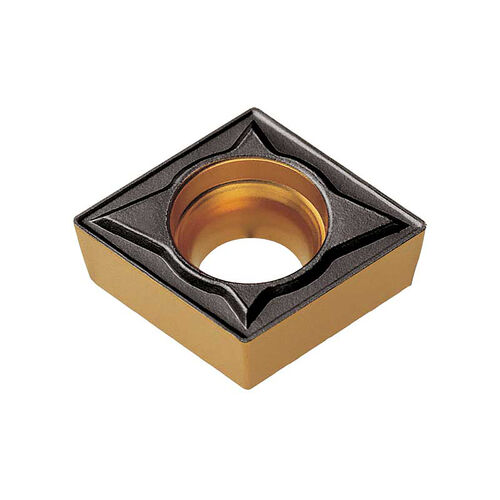
A small corner radius, usually 0.4 mm or below, is used when profile accuracy, low radial force, or tight part geometry matters more than roughing strength. If a drawing calls for a small internal corner, relief radius, or shoulder transition, the insert radius must be small enough to physically generate that shape. A 0.8 mm insert cannot cut a 0.4 mm inside radius.
Small radii also help on weak setups. Slender shafts, thin-wall parts, small diameters, long boring bars, and delicate finishing cuts often respond better to a smaller corner radius because radial force is lower. This can reduce deflection and help hold size.
The tradeoff is durability. A small radius concentrates heat and force in less carbide. Under medium or heavy load, it wears quickly and chips more easily. It is usually a finishing tool, not an all-purpose answer.
Small radii can still produce excellent surfaces if feed is controlled. For fine turning, feeds around 0.05 to 0.12 mm/rev are common starting points, depending on material, insert geometry, machine condition, and finish target. If the feed is too low, however, the edge may rub instead of cutting cleanly, especially on work-hardening alloys.
Corner Radius, Feed, and Surface Finish
Theoretical surface roughness improves as corner radius increases or feed decreases. That relationship is useful, but it is not the whole story. Actual finish also depends on vibration, built-up edge, material tearing, chip control, coolant, insert edge prep, and machine condition.
If a larger radius improves finish on one part and makes finish worse on another, rigidity is often the difference. A stable workpiece benefits from lower scallop height. A flexible workpiece may chatter because radial force rises.
The feed must also match the chipbreaker. A finishing chipbreaker may need a certain minimum chip thickness to curl and break the chip. Too low a feed can create long stringy chips and rubbing. Too high a feed can overload a small radius or finishing edge. The catalog range for the chipbreaker matters as much as the radius printed in the insert code.
Corner radius | Typical role | Strength | Cutting force tendency | Common caution |
0.2 mm | Fine finishing, small profiles, light cuts | Low | Low radial force | Wears fast if feed or depth is too high |
0.4 mm | General finishing, light profiling, weak setups | Low to medium | Moderate-low | Needs controlled feed and stable edge engagement |
0.8 mm | General turning and semi-finishing | Balanced | Moderate | Check drawing corner limits and ap |
1.2 mm | Medium roughing, stable semi-finishing | Medium-high | Moderate-high | Can chatter on slender or thin parts |
1.6 mm+ | Roughing, interrupted cuts, heavy stock removal | High | High radial force | Requires strong machine, holder, clamping, and workpiece rigidity |
Match Radius to the Operation
For roughing, choose the largest radius the setup can support, as long as the part geometry allows it and ap is not too shallow. The goal is edge strength, feed capacity, and resistance to impact. If the part is interrupted or has hard scale, radius alone is not enough; select a tough grade and a roughing chipbreaker as well.
For semi-finishing, start with a medium radius. A 0.8 mm insert is often a practical baseline because it supports stable tool life without demanding extreme rigidity. Move up if the machine is stable and feed needs to increase. Move down if chatter, deflection, or tight corner geometry is limiting the process.
For finishing, select the radius from the drawing and the setup. If the required corner is small or the part is flexible, choose 0.2 mm or 0.4 mm. If the part is rigid and the finish target is the main driver, 0.8 mm may be suitable, especially with a finishing or wiper insert. Do not assume a larger radius will fix finish if chatter is already present.
Operation | Practical radius direction | Why it works | Watch for |
Heavy rough turning | 1.2 mm to 1.6 mm+ | Stronger edge, better heat spreading, higher feed capacity | Machine power, radial force, interrupted entry |
General OD turning | 0.8 mm | Balanced life, finish, and force | Part corner limits and depth of cut |
Semi-finishing | 0.4 mm to 0.8 mm | Good finish with manageable cutting force | Chipbreaker range and stock consistency |
Fine finishing | 0.2 mm to 0.4 mm | Low force, small profiles, controlled size | Edge wear, rubbing at very low feed |
Slender shaft or thin wall | Smaller than standard | Reduces radial push and deflection | Tool life under heavier load |
Cast skin or interrupted cut | Larger, with tough grade | Improves corner strength | Requires rigid clamping and enough ap |
Rigidity Decides How Far You Can Push the Radius
Corner radius selection should include the entire machining system, not just the insert. A rigid system includes adequate spindle power, tight turret and holder clamping, short tool overhang, stable workholding, and a workpiece that does not flex easily.
In a weak system, even a good insert can behave badly. A long boring bar, for example, may chatter with a radius that works perfectly on an external turning tool. A thin-wall tube may deflect under radial pressure and spring back after the cut, leaving size error. A slender shaft may show a repeating pattern that looks like a speed problem but is actually a force-direction problem.
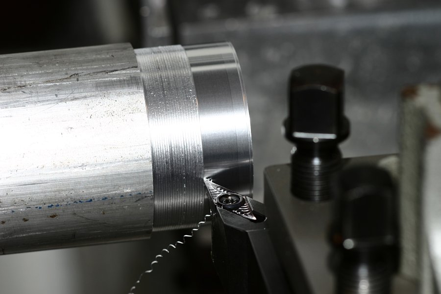
When troubleshooting, do not change one variable blindly. If chatter appears after switching from 0.4 mm to 0.8 mm radius, the radius may be the cause. If tool life drops after switching from 0.8 mm to 0.2 mm radius while keeping the same roughing data, the smaller corner is probably overloaded.
Common Problems and Radius-Related Fixes
Problem on the lathe | Radius-related cause | Practical correction |
Chatter after increasing corner radius | Radial force increased beyond setup rigidity | Reduce radius, shorten overhang, improve clamping, or reduce feed/depth carefully |
Good theoretical finish but visible vibration marks | Large radius is exciting a flexible workpiece or holder | Try a smaller radius before chasing speed changes |
Fast corner wear on finishing insert | Radius is too small for the load or feed | Increase radius if geometry allows, reduce stock, or use a stronger finishing grade |
Poor finish at shallow depth of cut | ap is too small relative to R, causing rubbing or plowing | Use a smaller radius, increase engagement, or choose sharper finishing geometry |
Cannot machine drawing corner | Insert radius is larger than required part radius | Select an insert radius equal to or smaller than the specified corner |
Chips do not break in finishing | Feed/depth is outside chipbreaker working range | Adjust feed within the chipbreaker range or change chipbreaker style |
Size drift on slender parts | Radial pressure deflects the part | Use a smaller radius, sharper positive geometry, lighter passes, and better support |
Buyer Checklist for Standardizing Corner Radius
For tooling buyers, the best inventory is not the smallest number of inserts. It is the smallest number that still covers the real process windows.
A useful starting set for general CNC turning might include:
- 4 mm for finishing, smaller profiles, and lower-force cuts
- 8 mm as the default general turning and semi-finishing radius
- 2 mm or 1.6 mm for stable roughing and heavier cuts
That simple structure works better when each radius is paired with the right chipbreaker and grade. A 0.8 mm finishing chipbreaker and a 0.8 mm roughing chipbreaker do not behave the same way. The radius is only one part of the insert system.
Before standardizing, review the jobs that create the most scrap, downtime, or tool changes. Check part material, stock condition, drawing corner limits, average depth of cut, and machine rigidity. The goal is to stock radii that match repeat work, not to fill drawers with every catalog option.
Practical Selection Sequence
Start with the drawing. If the part has a maximum corner radius, the insert must fit it. Next, look at the operation: roughing, semi-finishing, finishing, profiling, boring, or interrupted cutting. Then compare ap with the proposed corner radius. If depth of cut is regularly below the radius, be careful with large radii unless the setup is proven stable.
After that, judge rigidity. A strong machine and short toolholder allow more radius and feed. A weak system often needs a smaller radius and sharper geometry. Finally, confirm the chipbreaker and grade. If those do not match the material and chip thickness, the radius cannot rescue the process.
This sequence keeps the decision grounded in the cut, not in habit. It also helps engineers and buyers discuss insert choices in the same language: part geometry, force direction, finish target, tool life, and process stability.

Conclusion
Turning insert corner radius is a balancing point between edge strength, surface finish, radial force, profile access, and tool life. Large radii are productive in rigid roughing setups. Medium radii are the everyday choice for stable general turning. Small radii protect finishing accuracy, reduce radial force, and reach tight profiles, but they should not be overloaded.
The most important rule is to check whether the depth of cut is appropriate for the radius. When ap is too small relative to R, the cut can shift from clean shearing toward rubbing and radial pushing. That is where many surface finish and chatter problems begin.
HNCarbide supplies carbide turning inserts for roughing, semi-finishing, and finishing applications. If your shop is standardizing insert radii for CNC lathe work, start with the part geometry, real depth of cut, and machine rigidity, then choose the grade and chipbreaker around that process window.




