
How to Choose the Right Turning Insert?A Practical CNC Guide That Actually Improves Tool Life and Surface Finish
Table of Contents
Choosing a turning insert sounds simple—until you realize how many variables are involved. Why does one insert last twice as long as another under seemingly identical conditions? Why do some setups produce perfect finishes while others generate chatter and rapid wear?
The answer lies not in a single factor, but in the interaction between insert material, geometry, coating, cutting parameters, and machine stability. In modern CNC machining, especially when working with steel, stainless steel, and aluminum alloys, selecting the right insert is no longer just a technical decision—it is a key factor in productivity and cost control.
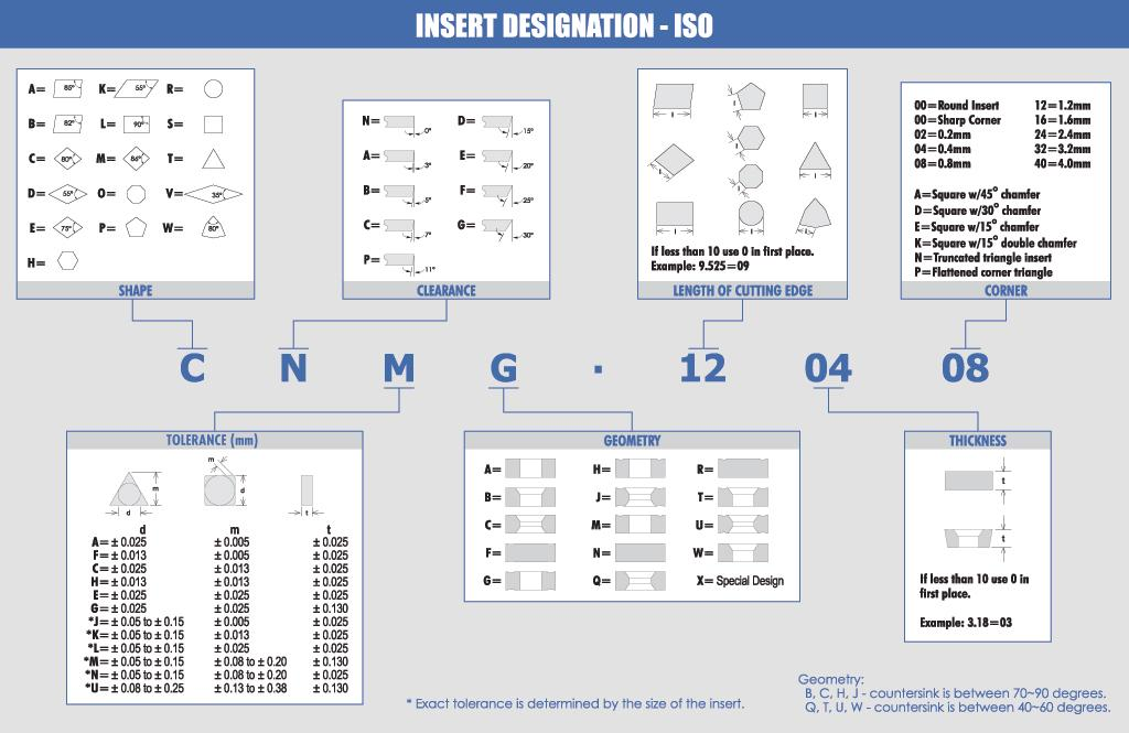
This guide breaks down how to select turning inserts in a way that is both practical and verifiable, focusing on real machining conditions and widely used insert systems such as CNMG, DNMG, VNMG, and WNMG.
Why Is Insert Selection So Critical in CNC Turning?
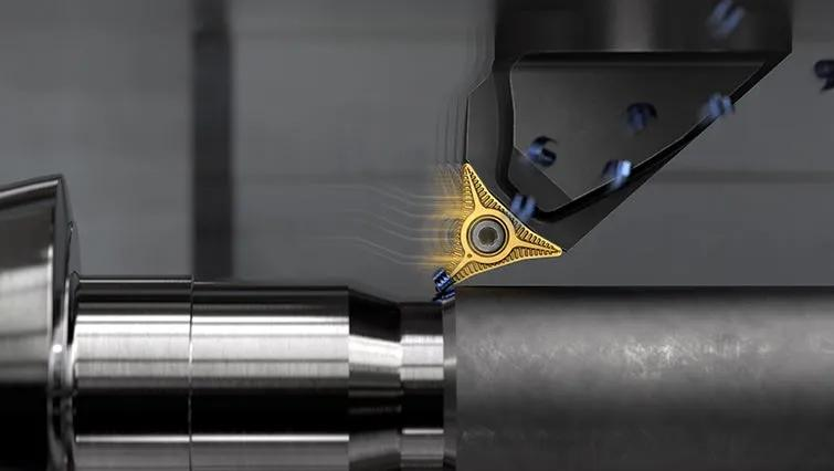
Many machinists underestimate how much influence the insert has on the final result. In reality, the insert is the only component directly interacting with the workpiece, which means it determines chip formation, heat generation, and surface integrity.
A poorly selected insert often leads to excessive flank wear, unstable cutting, and inconsistent chip evacuation. On the other hand, a well-matched insert can significantly extend tool life, allow higher feed rates, and produce a more consistent surface finish.
This becomes even more important in automated or high-volume production, where even a small improvement in insert performance can translate into substantial cost savings over time.
What Insert Material Should You Choose for Different Workpieces?
Material selection is usually the first step, but also one of the most misunderstood. While carbide inserts dominate modern machining, not all carbide inserts perform the same. The substrate composition and coating technology define how the insert behaves under heat, pressure, and wear.
In most industrial applications today, coated carbide inserts are preferred. These inserts combine a tough carbide substrate with advanced coatings such as TiAlN, Al₂O₃, or multilayer CVD coatings, which improve wear resistance and thermal stability.
Insert Material Comparison
Material Type | Wear Resistance | Toughness | Typical Application |
Uncoated Carbide | Medium | High | Aluminum, light cutting |
Coated Carbide | High | Medium-High | Steel, stainless steel |
Ceramic | Very High | Low | High-speed finishing |
CBN | Extremely High | Medium | Hardened steel |
PCD | Extremely High | Low | Aluminum, composites |
In practical terms, most CNC shops rely heavily on coated carbide inserts for general turning. For example, a PVD-coated grade performs well in stainless steel due to its better edge toughness, while a CVD-coated grade is often preferred for continuous cutting in steel due to its superior wear resistance.
How Does ISO Classification Actually Help You Choose?
The ISO system is widely used, but many users only have a superficial understanding of it. The classification divides machining materials into groups such as P (steel), M (stainless steel), and K (cast iron), and assigns grades like P10, P20, or P40.
But what do these numbers really mean?
They represent a balance between hardness and toughness. Lower numbers indicate higher wear resistance, making them suitable for finishing, while higher numbers indicate better toughness for roughing.
ISO Application Range
ISO Code | Performance Focus | Typical Use |
P10 | High wear resistance | Finishing steel |
P20 | Balanced | General machining |
P40 | High toughness | Roughing steel |
M10 | Sharp, wear-resistant | Stainless finishing |
K30 | Tough, stable | Cast iron roughing |
However, it is important to understand that ISO classification is not absolute. Two inserts labeled “P20” from different manufacturers may perform very differently due to variations in coating structure and carbide grain size. Therefore, comparisons are most reliable within the same brand or product series.
Which Insert Shape Works Best for Your Application?
Insert geometry is where theory meets real-world machining. The shape of the insert determines how much cutting force it can handle and how easily it can access complex features.
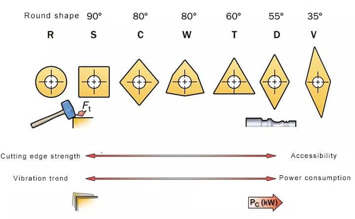
In general, inserts with larger included angles, such as CNMG (80°) or WNMG (80° trigon), provide stronger cutting edges and are ideal for roughing operations. These geometries distribute cutting forces more evenly and are less prone to chipping.
Smaller-angle inserts, such as VNMG (35°), offer better accessibility and are commonly used for finishing or profiling. However, their sharp angles make them more fragile, especially under heavy loads.
Round inserts represent the extreme case, offering maximum edge strength and excellent performance in heavy or interrupted cuts, although they require higher machine power and rigidity.
How Do You Balance Strength and Precision in Insert Geometry?
The key question is not simply “which shape is best,” but rather “which shape fits your cutting conditions?”
If your machine setup is rigid and you are removing large amounts of material, a strong geometry like CNMG or SNMG is typically the safest choice. These inserts allow higher feed rates and longer tool life.
If, however, you are performing finishing operations or machining complex contours, a sharper geometry such as DNMG or VNMG will provide better surface quality and accessibility.
This balance between strength and precision is one of the most important decisions in insert selection, and it often determines whether a process is stable or prone to vibration.
What Role Does Nose Radius Play in Surface Finish?
The nose radius is often overlooked, but it has a direct impact on both surface finish and cutting stability. A larger nose radius improves edge strength and allows higher feed rates, but it also increases cutting forces.
Nose Radius vs Feed Rate
Nose Radius (mm) | Recommended Max Feed (mm/rev) | Application |
0.2 | 0.10–0.16 | Fine finishing |
0.4 | 0.20–0.32 | General finishing |
0.8 | 0.30–0.50 | Semi-finishing |
1.2–1.6 | 0.50–0.80 | Roughing |
As a general rule, the feed rate should not exceed approximately 80% of the nose radius. Exceeding this limit often leads to poor surface finish and unstable cutting conditions.
In practice, machinists often reduce nose radius when encountering vibration, even if it means sacrificing some productivity.
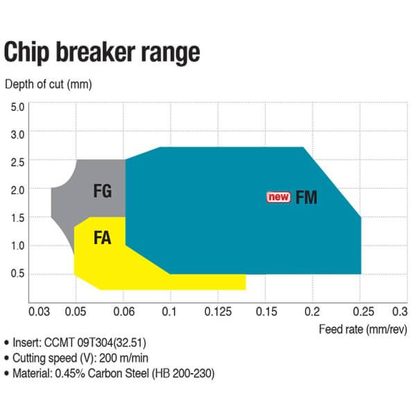
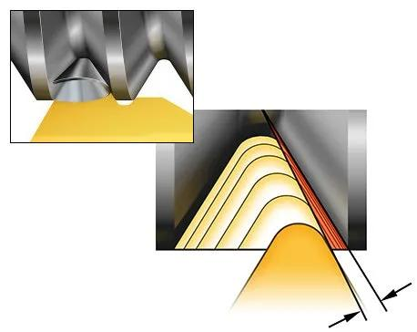
How Do Chipbreakers Affect Machining Performance?
Chip control is one of the most visible indicators of a well-optimized cutting process. Poor chip control leads to long, tangled chips that damage the workpiece and interfere with automation.
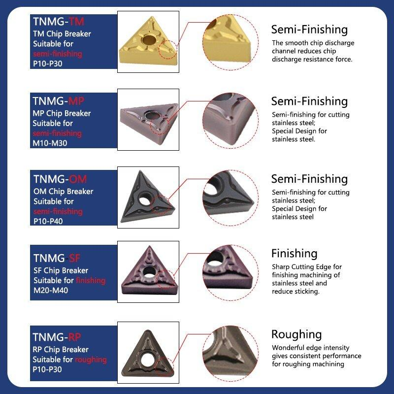
Modern inserts use carefully designed chipbreaker geometries to control chip flow. These are typically classified into finishing (F), medium (M), and roughing (R) types.
A finishing chipbreaker produces small, controlled chips at low feed rates, while a roughing chipbreaker requires higher feed and depth of cut to function properly.
However, it is important to understand that chip control is not determined by geometry alone. Cutting parameters—especially feed rate—play a critical role. Even the best chipbreaker will fail if used outside its optimal range.
Are You Overlooking Insert Clamping and Setup?
Even the best insert will fail if it is not properly mounted. Insert clamping systems, whether screw-type or top-clamp designs, must ensure stability and precise positioning.
Before installing an insert, all contact surfaces should be clean and free of debris. Even a small chip trapped under the insert can cause misalignment, leading to uneven wear and poor surface finish.
Tool overhang is another critical factor. Excessive overhang reduces rigidity and increases the likelihood of vibration. As a rule of thumb, the overhang should not exceed 1.5 times the shank height whenever possible.
How Can You Optimize Insert Selection for Real Production?
In real-world machining, insert selection is rarely a one-time decision. It is an iterative process that involves testing, observation, and adjustment.
Start with a recommended grade and geometry based on your material and operation. Then refine your selection by adjusting cutting parameters and observing wear patterns. Is the insert wearing too quickly? You may need a more wear-resistant grade. Is it chipping? A tougher grade or stronger geometry may be required.
This approach allows you to move beyond theoretical selection and achieve practical optimization tailored to your specific setup.

Conclusion: Is There Really a “Best” Turning Insert?
The idea of a single “best” insert is misleading. The optimal insert is always application-specific, defined by the combination of material, geometry, coating, and cutting conditions.
By understanding how these factors interact—and by making informed adjustments based on real machining feedback—you can significantly improve efficiency, extend tool life, and achieve more consistent results.
For manufacturers and tool suppliers alike, mastering insert selection is not just a technical skill—it is a competitive advantage.


