 Skip to content
How to Choose the Right End Milling Method: Slotting, Shoulder Milling, 3D Profiling, Plunge, Ramping, and Helical Interpolation
Table of Contents
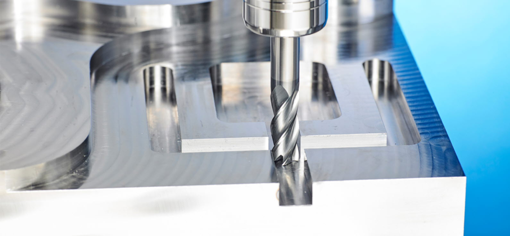
Choosing an end mill is only half of the machining decision. The other half is choosing how the cutter enters, engages, and leaves the workpiece. The same carbide end mill can behave very differently in a full slot, a light side cut, a ramp entry, a 3D finishing pass, or a helical hole-making cycle.
For production teams, this choice affects cycle time, chip evacuation, tool life, tolerance control, spindle load, surface finish, and even whether the part can be machined reliably on the available machine. For tooling buyers, it also affects which cutter geometry is worth paying for: flute count, coating, center-cutting capability, corner radius, neck relief, and overall rigidity.
This guide explains six common end milling methods and how to choose between them in real shop-floor conditions: slot milling, side or square shoulder milling, 3D profiling, plunge milling, ramp milling, and helical interpolation.
Start With the Conditions, Not the Toolpath
Before comparing milling methods, check the workpiece and machine conditions that will shape the decision. A toolpath that works well in pre-machined aluminum may chatter badly in forged alloy steel. A high-removal strategy on a rigid machining center may be too aggressive for an older machine with limited spindle power or toolholder stiffness.
The main factors are:
Factor | What to Check | Why It Changes the Milling Method |
Workpiece material | Composition, hardness, abrasiveness, heat resistance | Hard steel, stainless steel, cast iron, and non-ferrous alloys produce different cutting loads and chip behavior. |
Material condition | Forged, cast, hot rolled, cold drawn, scaled, interrupted skin | Uneven stock and hard skin may require a more stable engagement method before finishing. |
Cutting type | Full slot, side cut, pocketing, profiling, hole enlargement, surface finishing | The engagement width and chip thickness change dramatically by operation type. |
Machine condition | Spindle power, rigidity, toolholder quality, control capability, coolant delivery | Older or less rigid machines often need lower engagement and smoother entry strategies. |
Operation length | Short cut, long slot, deep wall, long-reach machining | Long cuts expose problems in heat, chip packing, deflection, and vibration. |
These conditions should drive the method. The goal is not to use the fastest-looking strategy on paper, but to keep cutting forces predictable enough that the machine, tool, and workpiece can hold the target tolerance.
1. Slot Milling
Slot milling uses the full cutter diameter to machine a channel or groove. It is one of the most common end milling operations because it is easy to program and can remove material quickly when the setup is rigid.
The advantage is simple: the whole cutter diameter is working. For an open slot or a straight groove, this can give high material removal with straightforward toolpaths. It is especially attractive when the slot width matches a standard cutter diameter and the tolerance is not extremely tight.
The tradeoff is high engagement. In a full-width slot, the cutter is surrounded by material across its diameter. Cutting forces rise, chips have less room to escape, and heat builds quickly. Slot milling also creates changing cutting conditions around the tool, so both climb and conventional milling effects may appear during the cut. This can lead to different surface quality on each wall.
Slot milling is usually a good choice when the slot is short to medium length, the machine is rigid, the workholding is solid, and chip evacuation is reliable. It becomes more difficult in deep slots, sticky materials, long slots, and tight tolerance grooves. In those cases, roughing with a smaller cutter, trochoidal milling, pre-drilling, or using a center-cutting end mill for entry may be more stable.
For blind or nearly enclosed slots, think carefully about entry. A drill, a center-cutting end mill, or a pilot hole may be needed before slotting begins. Without a controlled entry, the tool can rub, overload, or pack chips at the bottom of the feature.
2. Side Milling and Square Shoulder Milling
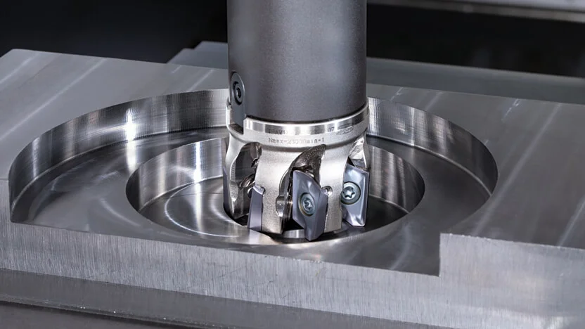
Side milling, often called square shoulder milling when a 90-degree wall is required, uses the side cutting edge of the end mill to machine a wall, step, or shoulder. Compared with full slotting, the radial engagement is usually smaller, so the operation can be easier to stabilize.
The main advantage is that the full flute length can participate in cutting, depending on axial depth. Programming is also simple: the cutter follows the edge of the workpiece or pocket wall. Because the width of cut can be kept small, side milling is often better for finishing walls, improving dimensional accuracy, and controlling surface finish.
The main limitation is axial depth of cut. A long axial engagement creates deflection and can leave taper or chatter marks on the wall. The deeper the wall, the more important cutter rigidity, flute length, neck relief, runout, and toolholder stiffness become.
For roughing a shoulder, use a method that keeps radial engagement under control. For finishing, leave a small, consistent stock allowance and use a separate finish pass. This is usually more reliable than trying to achieve both high material removal and final wall quality in one heavy pass.
3. Profiling and 3D Milling
3D profiling is used for curved surfaces, mold cavities, dies, aerospace features, and any geometry where the tool must follow changing contours. Ball nose and corner-radius end mills are common choices, although the best cutter depends on the surface shape and required finish.
This method works best on open surfaces where the tool can approach the feature without being trapped by surrounding walls. It also depends heavily on the CNC control, CAM strategy, and machine motion quality. Smooth look-ahead, accurate interpolation, and stable feed control matter as much as the cutter itself.
One important detail is tool center speed. With a ball nose end mill, cutting speed approaches zero at the very center of the tip. If the tool is held vertical and the center point does most of the work, rubbing and poor finish can appear. Tilting the milling axis, where the machine and setup allow it, moves the cutting contact away from the dead center and improves cutting action.
3D milling is rarely about the highest removal rate. It is about surface accuracy, blending, scallop control, and toolpath smoothness. For roughing, use an efficient stock removal strategy first. Reserve 3D finishing passes for controlled, consistent material removal.
4. Plunge Milling
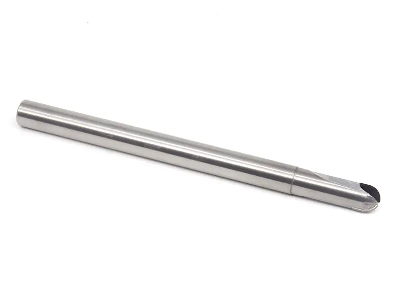
Plunge milling feeds the cutter mainly in the axial direction, similar to drilling with a milling cutter. It is useful when radial cutting forces need to be reduced, such as deep pockets, long-reach tools, weak setups, or machines that are more stable in the Z axis than in lateral cutting.
Plunge milling can create a flat bottom and can enter angled or uneven surfaces more easily than a standard drill in some cases. It can also replace drilling in certain roughing operations, especially when the feature is not a simple round hole. Programming is generally straightforward: the cutter makes repeated plunges with controlled step-over.
The downside is productivity. Material removal is usually lower than with aggressive side cutting or high-efficiency milling. Chip evacuation can also be weak because chips are pushed into a confined area. At the tool center, impact and rubbing can be severe if the cutter geometry is not designed for center cutting.
Use plunge milling when stability matters more than speed. It is not the first choice for every pocket, but it can save a difficult job where side forces would bend the tool or excite chatter.
5. Ramp Milling
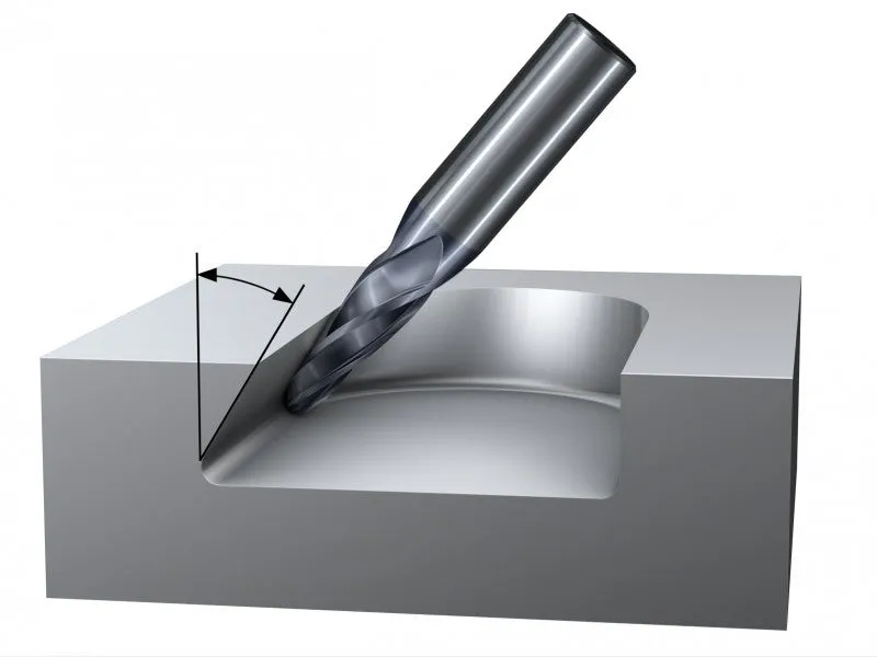
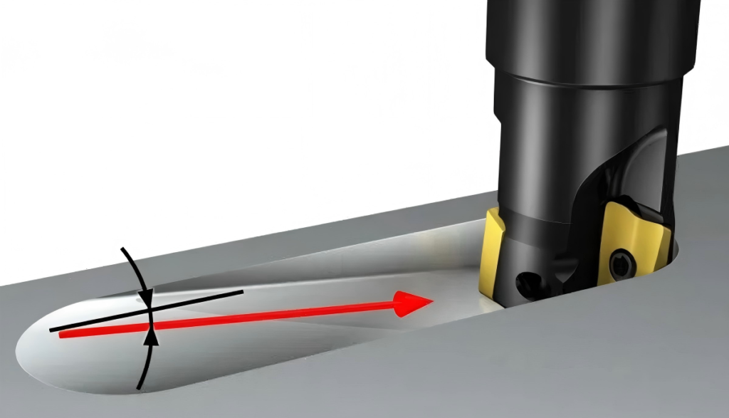
Ramp milling enters the material along a sloped path rather than plunging straight down. It is widely used for pocket entry, cavity roughing, and opening a feature without pre-drilling. When the cutter is suitable for ramping, the cutting edges can be used more efficiently than in straight plunging.
The benefits are strong: cutting parameters can often be higher than plunge milling, material removal can be good, and programming is not difficult in modern CAM systems. Ramp milling also avoids a separate drilling operation in many pockets, which saves tool changes and setup time.
The limitation is ramp angle. Every cutter has a practical ramping capability based on end geometry, flute space, coating, tool diameter, and material. Too steep an angle overloads the center cutting area and can create heat, poor chips, or breakage. Ramp milling can also create visible marks on the wall because climb and conventional cutting effects may happen during the entry motion.
For production work, keep the ramp angle conservative unless the tool supplier gives a reliable recommendation for the material. Use coolant or air blast to keep chips moving out of the entry path, especially in ductile materials.
6. Helical Interpolation
Helical interpolation combines circular XY motion with a controlled Z feed. The cutter follows a spiral path to open or enlarge a hole, machine circular pockets, or create internal features of different diameters. It is especially useful when one cutter must produce several hole sizes.
The biggest advantage is chip evacuation. The circular path gives chips more room to move compared with a straight plunge. It also uses more of the cutting edge and allows one end mill to machine different diameters without changing tools.
The tradeoff is that metal removal rate is often lower than drilling or aggressive pocketing. Programming also requires more care. The tool diameter, hole diameter, pitch, radial engagement, entry, exit, and machine interpolation quality all matter. A poor helical path can leave spiral marks, overload the cutter, or produce an inaccurate diameter.
Helical interpolation is a strong choice when flexibility matters, when hole diameter is non-standard, or when drilling is not suitable because of material, feature shape, or bottom condition. For high-volume standard holes, drilling may still be faster.
Quick Comparison of the Six Milling Methods
Milling Method | Best Used For | Main Strength | Main Limitation |
Slot milling | Straight slots, grooves, simple channel features | High removal rate and simple programming | High engagement, chip packing, vibration, harder tolerance control |
Side or square shoulder milling | Walls, steps, shoulders, finish passes | Lower radial engagement and good wall control | Axial depth can cause deflection and chatter |
3D profiling | Mold surfaces, curved profiles, freeform features | Surface control on complex geometry | Requires modern control, CAM quality, and careful tool orientation |
Plunge milling | Deep pockets, long-reach roughing, weak setups | Lower radial force and stable Z-axis loading | Lower removal rate and weaker chip evacuation |
Ramp milling | Pocket entry, cavity opening, roughing without pre-drilling | Efficient entry and good edge utilization | Limited by ramp angle and chip control |
Helical interpolation | Hole opening, circular pockets, multiple diameters | Flexible diameters and better chip evacuation than plunge entry | Slower than drilling and more demanding programming |
Matching Method to Material and Workpiece Condition
Material condition can matter as much as material grade. A cast surface may have scale, sand, or interrupted contact. A forged blank may have hard spots. Hot-rolled stock can have a tough skin. Cold-drawn material may be dimensionally better but can still create workholding and burr challenges depending on the alloy.
Workpiece Situation | Practical Milling Focus | Suitable Method Bias |
Hard alloy steel or pre-hardened steel | Control heat, avoid rubbing, maintain stable engagement | Side milling, ramping, 3D finishing with proper tool orientation |
Stainless steel | Avoid chip packing and work hardening | Ramping, side milling, helical interpolation with strong chip evacuation |
Cast iron | Manage abrasive wear and surface skin | Side milling or stable slotting with suitable coating and dust/chip control |
Aluminum or non-ferrous alloys | Clear chips quickly, prevent built-up edge | Slotting, ramping, helical interpolation with polished flutes and high chip flow |
Forged or scaled stock | Survive uneven entry and hard skin | Conservative side milling, ramping, or roughing before finishing |
Long-reach or weak setup | Reduce lateral force | Plunge milling or light side milling with multiple passes |
Do not treat a catalog feed and speed value as a complete process plan. The engagement method changes chip thickness, heat, force direction, and evacuation. Adjust parameters after the method is selected.
Troubleshooting by Milling Method
Problem | Likely Cause | Adjustment to Try |
Chatter in a full slot | Too much radial engagement, poor chip evacuation, weak toolholding | Reduce depth, use smaller step-over strategy, improve holder rigidity, use air/coolant blast |
Tapered wall in shoulder milling | Tool deflection from excessive axial depth | Leave finish stock, reduce axial engagement, use shorter flute length or larger tool diameter |
Poor finish in 3D milling | Ball nose center rubbing or rough CAM motion | Tilt tool axis if possible, reduce step-over, improve finishing path smoothness |
Tool damage during plunge | Cutter not suitable for center cutting or chips trapped under tool | Use center-cutting geometry, reduce peck depth, improve chip removal |
Broken cutter during ramping | Ramp angle too steep or entry chips recut | Lower ramp angle, reduce feed, improve coolant or air blast |
Oversize or rough helical hole | Wrong compensation, poor interpolation, unstable pitch | Check tool diameter offset, reduce pitch, add finish spring pass |
How Buyers Should Specify End Mills for These Methods
For procurement teams, the right question is not simply “Do you have carbide end mills in this diameter?” A better question is “Which cutter geometry supports the operation we actually run?”
For slotting, look at flute space, coating, chip evacuation, and center-cutting capability. For shoulder milling, check flute length, corner strength, runout tolerance, and whether a corner radius would improve edge life. For 3D profiling, ball nose accuracy, neck clearance, surface finish, and coating consistency matter. For ramping and helical interpolation, end cutting geometry and chip evacuation become critical. For plunge milling, center strength and axial load capacity are more important than catalog appearance.
Buyers should also share real application information with the supplier: material grade and hardness, stock condition, machine type, toolholder, coolant method, target tolerance, depth, width, and batch size. This helps avoid over-buying a premium tool for a simple job or under-specifying a tool for a difficult one.
Practical Selection Checklist
Before locking the process, ask these questions:
Question | Why It Matters |
Is the cutter fully buried or only side engaged? | Full slotting creates much higher load and chip evacuation risk. |
Does the cutter need to cut at center? | Plunge, ramp, and some slot entries require suitable end geometry. |
Is chip evacuation open or confined? | Deep slots, blind pockets, and helical holes need active chip control. |
Is the operation roughing or finishing? | Roughing favors stability and removal; finishing favors consistency and low deflection. |
Is the machine rigid enough for the chosen engagement? | Weak machines need smoother, lighter, or more axial-force-friendly strategies. |
Is the feature long, deep, or hard to reach? | Long operations magnify heat, deflection, and vibration problems. |

Conclusion
End milling method selection is a process decision, not just a programming preference. Slot milling is simple and productive but demanding. Side milling gives better wall control when axial depth is managed. 3D profiling depends on CAM quality and tool orientation. Plunge milling reduces side force but sacrifices removal rate. Ramp milling is an efficient entry method when the ramp angle is realistic. Helical interpolation gives flexibility for holes and circular features, but it requires careful programming.
For shops machining different materials and batch sizes, the best results usually come from matching cutter geometry, machine capability, and toolpath engagement before chasing maximum feed rates. HNCarbide supports carbide end mill selection for slotting, shoulder milling, profiling, ramping, plunge, and helical applications where stable performance and practical tool life matter.





