
How to Balance Hardness and Toughness in Carbide Inserts for CNC Machining
Table of Contents
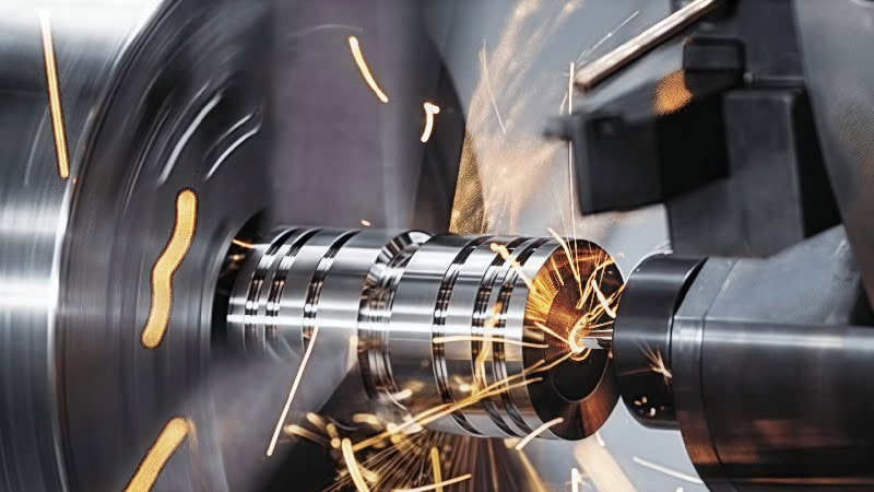
When a carbide insert fails early, the first reaction in many shops is to blame the insert grade. Sometimes that is fair. Just as often, the insert is being asked to do two opposite jobs at the same time: resist heat like a very hard grade and absorb shock like a very tough grade.
Hardness and toughness are not interchangeable. In carbide inserts, they sit on opposite sides of the same performance balance. A harder grade usually gives better wear resistance and hot hardness, which helps in fast, continuous cutting. A tougher grade usually survives impact, unstable cuts, heavy feed, and interrupted machining better. The best choice is rarely the hardest insert in the catalog or the toughest one on the shelf. It is the grade, coating, geometry, and cutting data that fit the real load at the cutting edge.
For machining engineers, CNC shop owners, and tooling buyers, this balance matters because it affects tool life, scrap risk, cycle time, and purchasing cost. A small mismatch can turn into crater wear, edge chipping, poor finish, broken corners, or a production line that keeps stopping for insert changes.
Hardness Means Wear Resistance, Especially Under Heat
In cutting-tool language, hardness is mainly about resisting wear and keeping the edge from softening at high temperature. During metal cutting, the chip slides across the rake face while the flank face rubs close to the newly machined surface. That contact zone can become extremely hot, especially in steel, stainless steel, titanium alloys, nickel alloys, and hardened materials.
Harder carbide grades, ceramic grades, CBN grades, and heat-resistant coatings help the cutting edge keep its shape under this temperature and abrasion. In continuous turning or stable finishing, that is exactly what the shop wants. The insert should wear gradually, hold size, and fail in a predictable way rather than breaking suddenly.
The tradeoff is brittleness. A very hard grade may not tolerate shock well. If the workpiece has keyways, interrupted surfaces, scale, forged skin, casting interruptions, or poor clamping, a highly wear-resistant grade may chip before it ever has the chance to wear out. The operator sees a broken corner and may think the insert was “bad,” when the more likely issue is that the insert had too much hot hardness and not enough fracture resistance for the operation.
Toughness Means Resistance to Shock and Edge Breakage
Toughness is the insert’s ability to absorb mechanical load without cracking. It becomes important when the cut is heavy, unstable, or interrupted. A roughing pass with a large depth of cut, a high feed, or an entry into an uneven surface asks more from the carbide substrate and edge preparation than a light finishing pass.
Tougher carbide grades often use a substrate and edge design that can carry higher mechanical stress. They are useful for interrupted cuts, less rigid workholding, long overhangs, rough stock, welded parts, and machines where vibration is difficult to remove completely.
The tradeoff is heat. A tougher grade may wear faster if used at high cutting speed in a stable continuous cut. The insert may survive the impact, but the rake face and flank face can wear away too quickly. In that situation, moving to a harder or more wear-resistant grade often improves cost per part.
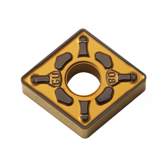
The Practical Balance: Read the Cut Before Changing the Grade
The most useful starting point is not the grade number alone. It is the behavior of the tool in the machine. A stable continuous cut that produces predictable flank wear is asking for a different insert than a rough interrupted cut that breaks corners after a few passes.
Cutting condition | Insert behavior needed | Typical grade direction |
Continuous finishing or semi-finishing in steel | Hot hardness, wear resistance, stable coating | Move toward a harder, more wear-resistant grade |
Heavy roughing with high feed or depth of cut | Strong edge, tough substrate, secure clamping | Move toward a tougher grade and stronger geometry |
Interrupted turning, keyways, scale, or cast surface | Impact resistance and controlled edge preparation | Favor toughness before chasing speed |
Stable hard turning | Hot hardness, edge strength, high-temperature stability | Consider hard-grade carbide, CBN, or ceramic depending on material and setup |
Poor rigidity, long overhang, weak workholding | Fracture resistance and lower cutting force | Use a tougher grade, smaller chip load, sharper/free-cutting geometry |
If the insert wears out gradually but too quickly, the grade may need more wear resistance. If the insert chips or breaks suddenly, the grade may need more toughness, or the setup may be unstable. If both happen together, do not jump straight to a new supplier. Check speed, feed, depth of cut, insert geometry, chipbreaker range, toolholder condition, insert seating, coolant delivery, and workholding.
Crater Wear: A Heat and Chip-Flow Warning
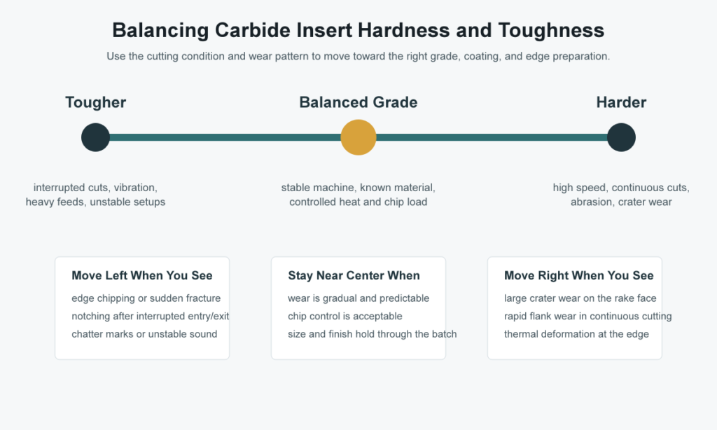
Crater wear appears as a concave depression on the rake face of the insert, usually where hot chips flow over the tool. In carbide cutting, it is often linked to diffusion wear at higher cutting speeds and abrasive action at lower or moderate speeds. Heat from the chip-tool contact can accelerate chemical and mechanical wear on the rake face. As the crater grows, the cutting edge becomes weaker and may eventually chip or collapse.
In real production, crater wear is especially important because it can hide until the edge strength is already reduced. The flank may not look terrible, but the rake face has lost support behind the edge. When the crater becomes deep enough, the insert can suddenly fail even though the shop expected more tool life.
To reduce crater wear, look first at heat and chip contact:
- Lower cutting speed if the operation allows it.
- Use a grade or coating with stronger high-temperature wear resistance.
- Check whether the chipbreaker is forcing too much chip contact on the rake face.
- Improve coolant direction when coolant is suitable for the material and operation.
- Use a freer-cutting geometry when cutting forces and heat are too high.
Crater wear does not automatically mean the insert is poor quality. It means the cutting edge is seeing too much heat, too much chip pressure, or not enough protection for the actual speed and material.
Chipping and Breakage: A Toughness or Stability Warning
A broken insert corner tells a different story. Chipping is usually a mechanical-load problem before it is a pure wear problem. The insert may be too hard or too sharp for the interruption, the feed may be too aggressive, or the machine-tool-workholding system may not be stable enough.
Before changing to a tougher grade, check the physical setup. A worn insert seat, damaged shim, loose clamp screw, long tool overhang, weak boring bar, or flexible workpiece can make a good insert behave badly. In milling, cutter runout and uneven insert height can overload one edge. In turning, a small seating issue can create a repeating shock at the same corner.
Failure sign | Likely direction | What to check before buying a new grade |
Large crater on rake face | Need more wear resistance or lower heat | Cutting speed, coating, coolant direction, chipbreaker contact |
Rapid flank wear in continuous cutting | Need more hardness or abrasion resistance | Workpiece hardness, surface scale, speed, coating choice |
Corner chipping at entry or exit | Need more toughness or stronger edge | Interrupted cut, approach angle, edge hone, feed at entry |
Sudden fracture in stable-looking cut | Setup may be unstable | Insert seating, holder pocket, clamping, workholding, runout |
Thermal cracks | Heat cycling problem | Coolant consistency, interrupted cut with coolant shock, speed |
This is why wear analysis is more valuable than guessing. A worn-out insert is not trash; it is evidence. The wear mark shows whether the failure is thermal, abrasive, mechanical, chemical, or a mix of several factors.
Continuous Cutting Usually Rewards Hardness
In a stable continuous turning operation, the insert is in contact with the workpiece without repeated impact. If the machine is rigid, the workpiece is clamped well, and the chip flow is controlled, the limiting factor often becomes wear resistance. The edge must survive heat and abrasion long enough to make the cycle economical.
This is where harder carbide grades and suitable coatings earn their place. Steel turning at productive speeds, finishing passes on consistent stock, and controlled medium turning often benefit from grades that resist crater wear and flank wear. A tougher grade may run, but it may wear too quickly and increase cost per part.
The practical warning is that “continuous” does not always mean “stable.” A long shaft can vibrate. A thin wall can flex. A bore can chatter. A machine with poor spindle condition can create impact even in what looks like a simple cut. If a hard grade chips in a continuous cut, check rigidity before assuming the operation only needs a tougher insert.
Interrupted Cutting Usually Rewards Toughness
Interrupted cutting changes the load completely. Each entry into the workpiece shocks the cutting edge. Keyways, splines, cross holes, cast skin, welded features, uneven forgings, and milling cutter exit conditions all punish brittle edges.
In these cases, a tougher carbide grade, stronger insert shape, larger included angle, reinforced cutting edge, and conservative entry conditions can matter more than maximum wear resistance. The shop may give up some speed, but it gains process security. That trade is often worth it when an insert failure can damage a part, holder, spindle, or fixture.
Hard Turning Adds Another Layer
Hard turning deserves special attention because the workpiece material may be much harder after heat treatment than it was in the soft state. A steel part that cuts easily before hardening may become a completely different machining problem after quenching and tempering.
For production planning, the first question is whether to machine before hardening, after hardening, or split the work between both stages. Soft machining can remove stock faster and with less tool stress. Hard machining can reduce grinding, improve process flow, and maintain accuracy after heat treatment. The right answer depends on tolerance, distortion, surface finish, batch size, and available machine rigidity.
Case-hardened and through-hardened parts also behave differently. A case-hardened part has a hard surface layer with a softer core underneath. A through-hardened part is hard throughout. The depth of cut decides what the insert is really cutting. A light finishing pass may stay mostly in the hard case, while a deeper cut may pass into softer material. That difference affects grade choice, edge preparation, and chip control.
For hardened steel, carbide can work in some ranges, especially at lower hardness or less demanding conditions. For stable finishing of harder materials, CBN or ceramic may become more economical despite higher insert price. The decision should be based on the full process: part value, tool life, surface finish, machine stability, and the cost of a broken edge.
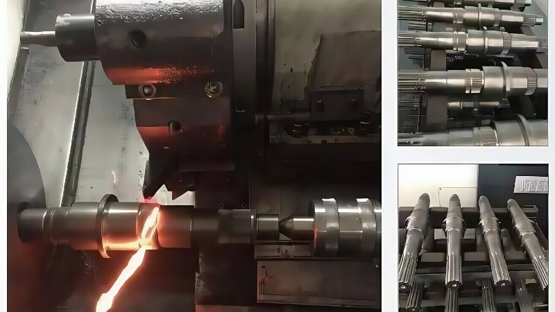
Do Not Ignore Geometry, Coating, and Edge Preparation
Grade selection is only one part of the balance. Two inserts with the same broad material category can behave very differently because of geometry and edge preparation.
A sharp positive geometry reduces cutting force and heat, which can help on less rigid machines or gummy materials. A stronger negative geometry supports the edge better and often suits heavier roughing. A honed or chamfered edge improves strength, but too much edge preparation can increase cutting force and heat. Coatings add another layer: CVD coatings often support high-temperature wear resistance in steel and cast iron, while PVD coatings are often useful where a sharper edge and toughness are needed.
Tool feature | How it shifts performance | Practical note |
Tougher substrate | Improves fracture resistance | Useful for interrupted cuts, roughing, and unstable setups |
Harder substrate | Improves wear resistance | Useful for stable, continuous, high-speed cutting |
Thicker CVD coating | Improves heat and crater-wear protection | Common in productive steel and cast iron turning |
PVD coating | Keeps a sharper edge and good toughness | Often useful for stainless, finishing, and lower-force cuts |
Strong edge hone/chamfer | Reduces chipping | Can raise cutting force if overused |
Positive/free-cutting chipbreaker | Lowers cutting force and heat | May be weaker in heavy roughing |
This is where catalog recommendations help, but they should not replace trial data. Use supplier grades as a starting window, then confirm with real wear patterns on the machine.
A Simple Shop-Floor Decision Process
When an insert does not last as expected, use a structured check before changing everything at once.
- Identify the failure mode. Is it flank wear, crater wear, chipping, thermal cracking, built-up edge, notching, or sudden breakage?
- Confirm the cutting condition. Is the cut continuous or interrupted? Is the setup rigid? Is the material harder than expected?
- Check whether the insert is being used inside its chipbreaker range. A chipbreaker outside its feed and depth-of-cut window can generate heat, poor chips, or edge overload.
- Inspect the holder and seating surfaces. A damaged pocket or loose clamp can destroy repeatability.
- Change one major variable at a time. Move grade, speed, feed, coolant, or geometry deliberately so the result teaches you something.
This approach prevents the common problem of chasing insert grades while the real cause is a worn toolholder, wrong chipbreaker, or unstable fixture.
What Tooling Buyers Should Ask Suppliers
For B2B buyers, the best insert is not just the one with the attractive unit price. Ask what application window the grade is designed for. Is it biased toward wear resistance or toughness? Which ISO material groups does it target? Is the coating better suited to continuous steel turning, stainless finishing, cast iron, hard turning, or interrupted cutting? What edge preparation is standard?
Also ask for recommended starting parameters, not just a grade code. A good supplier should be able to suggest speed, feed, depth of cut, coolant advice, and geometry based on material hardness, operation type, and machine rigidity. If the job involves hardened parts, provide the actual HRC range and whether the material is case-hardened or through-hardened.

Conclusion: Balance the Insert Around the Real Cut
Hardness gives a carbide insert the ability to resist heat and wear. Toughness gives it the ability to survive pressure, vibration, and impact. CNC machining needs both, but not in the same proportion for every job.
For stable continuous cutting, move toward wear resistance and hot hardness. For interrupted cutting, poor rigidity, rough stock, and heavy mechanical load, move toward toughness and stronger edge geometry. When crater wear appears, think heat and chip contact. When chipping appears, think mechanical shock and setup stability.
HNCarbide works with carbide cutting tools for practical CNC applications, including turning inserts, milling tools, drills, and end mills. If you are comparing carbide insert choices for steel, stainless, cast iron, aluminum, or hardened parts, start with the real machining condition rather than the grade name alone. That is where better tool life usually begins.




