
How Cutting Speed Affects Tool Life and Surface Finish in CNC Machining
Table of Contents
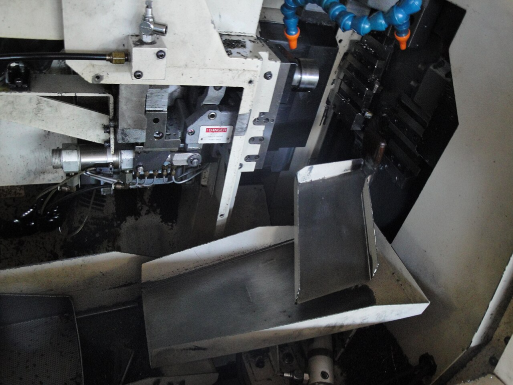
In many CNC shops, the first number an operator adjusts during setup is spindle speed. Behind that rpm value is a more important cutting condition: cutting speed, or surface speed.
Cutting speed is where productivity, tool cost, heat, chip formation, and surface finish meet. Raise it and the cycle time may improve. Push it too far and insert edges can fail long before the job is stable. Run it too low and the tool may survive longer, but the part can come off the machine with built-up edge marks, torn material, or a rougher finish than the drawing allows.
That is why cutting speed should not be treated as a simple “faster is better” setting. It is a control point. Used well, it helps a shop hold finish, protect the cutting edge, and lower cost per part. Used carelessly, it turns into one of the fastest ways to burn through carbide.
Cutting Speed Is More Than Spindle RPM
Spindle speed is measured in revolutions per minute. Cutting speed is the speed at which the cutting edge moves across the workpiece surface. In turning, it is tied to workpiece diameter. In milling, it is tied to cutter diameter.
For turning:
Metric | Common formula | Why it matters |
Cutting speed, metric | Vc = pi x D x n / 1000 | Vc in m/min, D in mm, n in rpm |
Spindle speed, metric | n = 1000 x Vc / (pi x D) | Larger diameters need lower rpm for the same surface speed |
Cutting speed, inch | SFM = pi x D x rpm / 12 | SFM in ft/min, D in inches |
This distinction matters because two jobs can run at the same rpm but very different surface speeds. A 10 mm bar and a 100 mm bar at the same rpm do not expose the cutting edge to the same heat or sliding distance. On a CNC lathe with constant surface speed enabled, rpm changes as the tool moves across the diameter so the programmed cutting speed stays closer to target.
In milling, tool diameter drives the same issue. A 20 mm carbide end mill at 6,000 rpm runs at a much higher cutting speed than a 6 mm end mill at the same rpm. That is why feed and speed charts normally start with tool diameter, workpiece material, tool grade, operation type, and coolant condition rather than rpm alone.
Why Higher Cutting Speed Shortens Tool Life
The classic relationship between cutting speed and tool life is often described by the Taylor tool life equation:
V x T^n = C
In this model, V is cutting speed, T is tool life, and n and C depend on the tool-workpiece combination. The useful point for daily machining is simple: tool life does not usually fall in a neat straight line as cutting speed rises. Because the relationship is a power law, a moderate speed increase can create a much larger loss in tool life than expected.
That does not mean every 20 percent speed increase cuts life by exactly the same amount in every shop. Tool grade, coating, work material, chip load, coolant, rigidity, interrupted cut, and wear criterion all change the result. But the direction is reliable: cutting speed is one of the strongest drivers of cutting temperature, and temperature is one of the strongest drivers of tool wear.
When surface speed rises, several wear mechanisms become more aggressive:
Wear mechanism | What higher cutting speed does | Typical shop-floor symptom |
Flank wear | Increases rubbing and heat along the clearance face | Finish drifts worse, size grows or shrinks, burrs increase |
Crater wear | Raises chip-tool interface temperature | Insert weakens behind the cutting edge |
Oxidation and coating breakdown | Pushes coating closer to its thermal limit | Edge loses protection, wear accelerates |
Diffusion wear | Encourages material transfer at high temperature | Fast wear in steels, stainless, titanium, or heat-resistant alloys |
Adhesion and built-up edge cycling | Can either reduce or worsen depending on speed window | Edge chipping, unstable finish, material welded to the cutting edge |
For carbide inserts, the early part of a stable tool-life curve is usually predictable: the edge wears gradually and the process stays controllable. Past a certain speed-temperature point, the insert can skip quickly into accelerated wear. The operator sees the same pattern: a tool that made several good parts suddenly starts leaving chatter marks, heavy flank wear, poor finish, or edge chipping.
This is why chasing cycle time only by raising rpm can be expensive. A 10 percent time saving on the cut may disappear if the job now needs twice as many inserts, extra offsets, more inspections, or unscheduled tool changes.
Tool Material Changes the Speed Window
Different tool materials tolerate cutting speed differently. High-speed steel, carbide, ceramic, CBN, and PCD are not interchangeable speed choices; they are designed for different heat, hardness, and work-material conditions.
Tool material | General speed tolerance | Practical note |
High-speed steel | Low to moderate | Tough and inexpensive, but sensitive to heat; best for lower-speed tools, unstable setups, and special forms |
Uncoated carbide | Moderate to high | Good balance for many steels, cast irons, and non-ferrous materials when edge sharpness matters |
Coated carbide | High | PVD/CVD coatings improve heat and wear resistance; grade selection must match material and operation |
Ceramic | Very high in suitable materials | Useful for high-speed finishing of cast iron and hardened materials, but less forgiving in unstable cuts |
CBN / PCD | Specialized high-performance range | Strong for hardened steels or abrasive non-ferrous materials, but application-specific and higher cost |
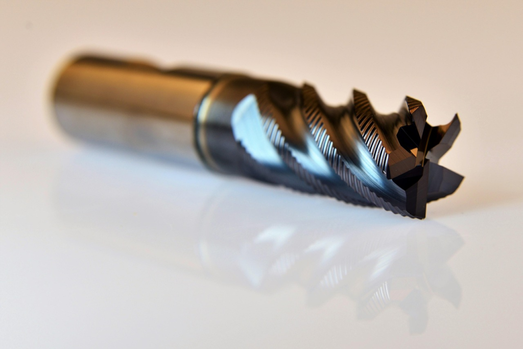
For most production shops using carbide, the real task is not finding the maximum possible speed. It is finding the speed that gives predictable tool life at the required surface finish. In high-volume work, predictability is often worth more than a few extra meters per minute.
How Cutting Speed Improves Surface Finish
Cutting speed can improve surface finish because it changes the way material flows across the edge. At very low speed, especially in ductile steels, aluminum, and stainless steels, workpiece material can weld temporarily to the rake face or cutting edge. This built-up edge acts like a rough, unstable extension of the tool.
When built-up edge grows and breaks away, it can tear the machined surface, change the effective edge geometry, and leave a finish that looks worse than the feed rate calculation predicted. Raising cutting speed often reduces built-up edge because the cutting zone becomes hot enough and the chip flow fast enough to prevent stable welding at the edge.
Higher speed also tends to produce smoother shearing when the tool, workholding, and machine are rigid enough. In finishing passes, this is one reason shops often run higher cutting speed than in roughing. The tool removes less material, cutting forces are lower, and the goal shifts from stock removal to dimensional control and surface quality.
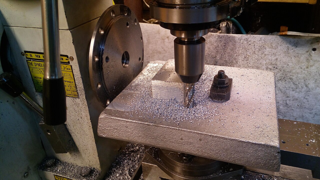
The important warning is that finish does not improve forever. Once cutting speed causes rapid flank wear, crater wear, edge rounding, or micro-chipping, the surface finish reverses direction. The edge is no longer sharp and stable. It starts rubbing, pushing material, and leaving inconsistent tool marks.
In practice, the speed-finish relationship often behaves like a U-shaped curve:
Cutting speed range | Common surface-finish behavior | Main risk |
Too low | Built-up edge, tearing, dull-looking surface, unstable chip flow | Poor finish even with a healthy tool |
Balanced | Clean chip formation, stable edge, repeatable finish | Requires monitoring as the tool wears |
Too high | Fast flank wear, edge rounding, thermal damage, chipping | Finish worsens and tool cost rises |
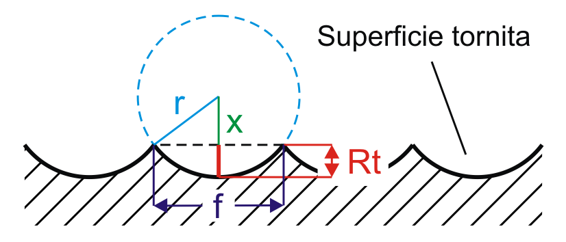
The best finish usually comes from a controlled middle window, not from the lowest or highest speed the machine can run.
Tool Wear Can Hide Behind a Good First Part
One trap in speed testing is judging the parameter from the first part only. A high cutting speed may produce a beautiful finish for the first few pieces because it suppresses built-up edge and creates clean chip flow. Ten minutes later, the same speed may be producing a dull edge, higher cutting force, and a rougher surface.
This is why finish checks should be tied to tool life, not separated from it. A cutting speed that makes one good sample part is not automatically a production parameter. For production, the question is sharper: can it hold size and finish through the planned tool-change interval?
Good shops look for signs that the speed is too high before the insert fails:
Observation | Likely speed-related cause | Practical correction |
Finish starts good, then worsens quickly | Flank wear or edge rounding is accelerating | Reduce cutting speed, review coating/grade, shorten tool-change interval |
Chips turn dark blue or straw-colored in steel | Excess heat at the chip-tool interface | Reduce speed, improve coolant aim, check chip load |
Insert edge chips near entry or exit | Thermal/mechanical shock or unstable edge | Lower speed, use tougher grade, adjust entry, reduce interruption severity |
Built-up edge appears at low speed | Material welding to the edge | Increase speed within tool-grade limits, use sharper geometry, improve lubrication |
Tool life varies widely between pockets or holders | Runout, rigidity, coolant, or clamping differences | Check setup before changing speed again |
Roughing and Finishing Should Not Share the Same Speed Logic
Roughing and finishing have different priorities. Treating them as the same operation is a common source of wasted inserts or disappointing finish.
In roughing, the tool is under heavier radial and axial load. Chip thickness is larger, heat generation is higher, and interruptions are more severe. A slightly conservative cutting speed often makes sense because tool security and chip evacuation are more important than the final surface. If a roughing insert fails early, it can damage the part, the holder, or the machine.
In finishing, the tool usually takes a smaller depth of cut and lower load. The pass must hold dimension and surface finish, so cutting speed can often be higher. The higher speed helps reduce built-up edge and improves shearing, but only if the edge remains stable long enough to finish the part count planned for that tool.
A useful setup habit is to separate the test:
Operation | Starting priority | Speed strategy |
Heavy roughing | Edge strength, chip control, stable load | Start below the catalog midpoint and increase only after chip evacuation and wear are stable |
Semi-finishing | Stock consistency for final pass | Use a stable speed that leaves predictable material and avoids work hardening |
Finishing | Size, surface roughness, edge sharpness | Use higher speed when it improves finish, but verify finish near the end of tool life |
This avoids the common mistake of using one “successful” speed across every stage of the job.
Start With the Catalog, Then Tune for the Real Setup
Cutting tool catalogs are a necessary starting point, but they are not a finished process plan. Catalog values are usually based on controlled test conditions: rigid setup, known material, suitable coolant, proper tool overhang, consistent stock, and a defined tool-life target.
On the shop floor, conditions are rarely that clean. A long boring bar, a thin-wall part, an interrupted scale-covered casting, a worn spindle, or poor coolant aim can all move the practical cutting speed lower. A stable horizontal machining center cutting clean steel can run a very different speed than a light-duty mill cutting the same material with a long toolholder.
For a new carbide setup, a sensible method is:
- Start around the conservative side of the tool supplier’s range, especially for roughing, long-reach tools, interrupted cuts, or hard materials.
- Keep feed per tooth or feed per revolution in the correct range so the tool cuts instead of rubbing.
- Watch the chip, the sound, the spindle load, and the first wear land rather than relying only on the first measured part.
- Increase cutting speed in controlled steps only after tool wear and finish are stable.
- Record the final speed together with material batch, coolant, toolholder, insert grade, edge prep, and tool-change interval.
The record matters. Without it, the next operator may only see an rpm number and repeat the parameter in a different diameter, tool, or material condition where it no longer makes sense.
The Cost Question: Fastest Is Not Always Cheapest
Cutting speed affects cost in two directions. Higher speed reduces cutting time, which is attractive when the machine is the bottleneck. Higher speed can also reduce tool life, increase inspection work, and create scrap risk.
The practical target is not maximum speed. It is minimum cost per good part at the required delivery rate.
For a short-run job, a shop may choose a safer speed because setup time, operator attention, and part risk dominate the economics. For a high-volume job, even a small improvement in cycle time may be worth testing, but only if insert indexing, offsets, and quality checks remain predictable.
When comparing two speed settings, look beyond cycle time:
Cost factor | What to compare |
Tool cost | Inserts or end mills consumed per batch |
Machine time | Actual cycle reduction, not just theoretical cutting time |
Labor | Tool changes, offset corrections, inspection frequency |
Quality | Scrap, rework, finish drift, burr removal |
Process reliability | Variation between operators, machines, and material lots |
The “golden” cutting speed is where productivity and tool life support each other. It is rarely the fastest value that worked once.
Practical Guidelines for Balancing Tool Life and Surface Finish
For carbide machining, these rules are useful starting points:
Situation | Recommended action |
Finish is rough at low speed and the edge shows built-up material | Raise cutting speed gradually, check lubrication, and consider a sharper geometry |
Tool life is short and wear is even across the flank | Reduce cutting speed before changing many other variables |
Edge chips rather than wears | Check rigidity, entry conditions, interrupted cut severity, and grade toughness before blaming speed alone |
Finish worsens near the end of a tool’s run | Shorten the tool-change interval or reduce speed enough to avoid accelerated wear |
Same insert works on one machine but fails on another | Compare runout, holder overhang, coolant delivery, spindle condition, and clamping |
Catalog speed looks too aggressive | Start at 70-80 percent of the recommended value for unstable or unknown conditions, then tune upward |
Cutting speed also interacts with feed. Reducing speed without keeping adequate chip load can create rubbing, heat, and poor finish. Increasing speed without adjusting feed can change chip color and tool temperature without improving real productivity. The best results usually come from tuning speed, feed, depth of cut, coolant, and tool grade as one system.

Conclusion
Cutting speed is one of the most powerful CNC machining parameters because it touches both sides of the process: tool life and surface finish. Higher speed can reduce built-up edge and improve finish, especially in finishing passes. Too much speed raises heat, accelerates wear, and can make surface roughness worse after the edge begins to fail.
The better approach is to find the working window for the material, tool grade, operation, and machine. Separate roughing from finishing. Use catalog values as a starting point, not a command. Watch tool wear over the intended tool-life interval, not just on the first part.
For shops evaluating carbide inserts, end mills, drills, or custom cutting tools, HNCarbide can help match tool material, coating, edge geometry, and cutting parameters to the real machining condition. The right cutting speed is not just a number on a setup sheet; it is the point where quality, tool life, and cost finally agree.




