Four Cutting Tool Wear Mechanisms and How to Extend Tool Life
Table of Contents
A cutting tool rarely fails for no reason. The reason is simply easy to miss.
An operator may see a chipped edge after the cycle, while the damage actually began much earlier as workpiece material welded to the rake face. A buyer may move to a more expensive carbide grade, yet tool life stays flat because heat, runout, or chip recutting remains unchanged. When every damaged tool is described as “worn out,” the shop loses the information contained in the wear pattern.
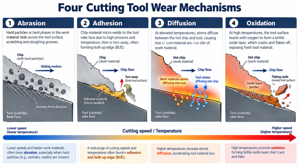
Four mechanisms explain much of the progressive material loss seen in metal cutting: abrasion, adhesion, diffusion, and oxidation. They often act together, and the dominant mechanism can change as speed, temperature, workpiece material, coating, or coolant delivery changes. Learning to separate them gives a shop a better starting point for parameter changes, grade selection, and tool-life trials.
First separate wear mechanisms from wear patterns
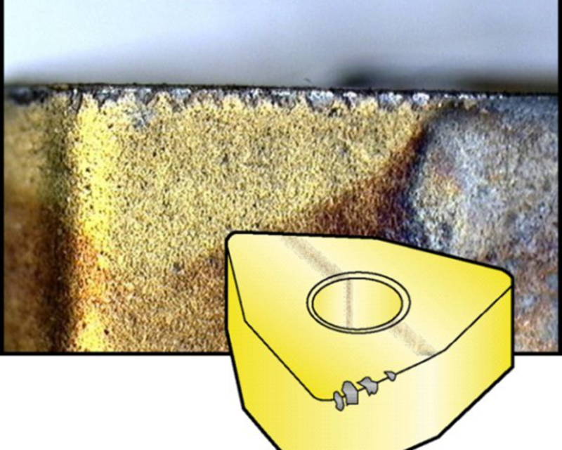
A wear mechanism is the physical or chemical process that removes tool material. A wear pattern is what remains visible on the edge. Flank wear, crater wear, notch wear, built-up edge, chipping, and thermal cracks are patterns or failure modes. Abrasion or diffusion may both contribute to flank wear. Crater wear may involve abrasion at lower temperature and diffusion or chemical degradation when the chip-tool interface becomes hotter.
This distinction matters because a photograph alone does not always reveal one clean cause. The visible pattern is evidence. The process history provides the rest: cutting speed, feed per tooth, radial and axial engagement, coolant condition, spindle load, runout, chip form, and the workpiece heat or lot.
Seco describes normal flank wear as the most predictable wear pattern and notes that its dominant cause can shift from abrasion at lower cutting speeds to diffusion at higher speeds. That is a useful reminder: speed bands are tendencies, not rigid borders.
1. Abrasive wear: hard phases plough the tool surface
Abrasive wear is mechanical. Hard constituents in the workpiece or chip slide across a softer tool surface and remove material by scratching, ploughing, or microcutting. Carbides in alloy steels, hard oxide scale, cast-skin particles, sand contamination in castings, and work-hardened fragments can all act as abrasives. Detached coating or carbide particles may create secondary abrasion when they are trapped at the interface.
The usual clues are fine grooves parallel to chip flow, a relatively even wear land on the flank, and a gradual increase in cutting force or part size. Abrasion is often prominent at lower cutting speeds, where thermally activated mechanisms are less aggressive. It can still remain important at high speed when the work material contains hard phases.
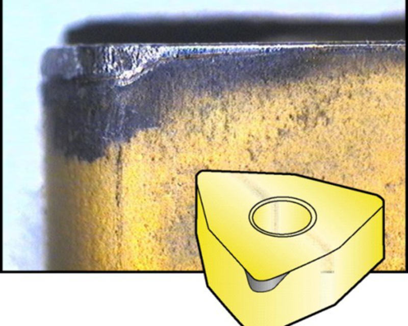
The first response should not automatically be “use the hardest grade.” A harder substrate may resist abrasion but can be less tolerant of impact, runout, or an interrupted cut. Check whether the wear is uniform across teeth or inserts. If one edge is much worse, runout, seat condition, holder accuracy, or spindle condition may be concentrating the load. If all edges show similar rapid wear, reduce surface speed in a controlled trial, improve chip removal, or evaluate a more wear-resistant grade and coating.
2. Adhesive wear: micro-welds form and tear away
Freshly cut metal is chemically active. Under high pressure and sufficient temperature, workpiece material can adhere to the rake face or cutting edge. The junction then shears as the chip moves, sometimes pulling small fragments from the coating or substrate. Repeated attachment and removal is adhesive wear.
Built-up edge is a familiar sign of this behavior, especially in ductile aluminum alloys, low-carbon steels, stainless steels, and heat-resistant alloys. It changes the effective edge geometry and can smear material onto the part. When the deposit breaks away, it may take part of the cutting edge with it, so adhesive wear can be mistaken for random chipping.
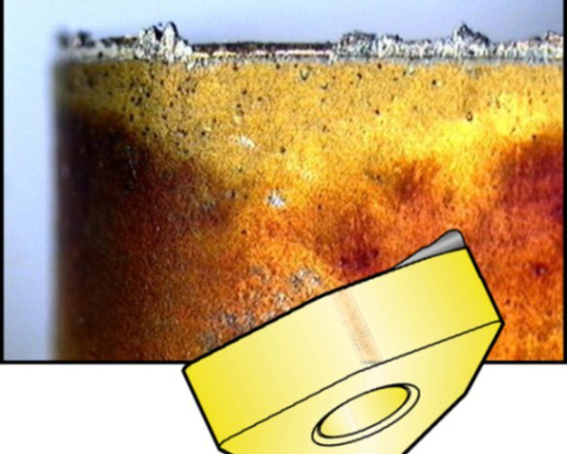
The common shop-floor cause is not simply “too much heat.” Adhesion often becomes troublesome in a middle or low speed range where pressure is high and the chip does not move cleanly across the rake face. Rubbing from low chip load makes it worse. A sharper geometry, polished rake or flute surface, suitable low-affinity coating, stable feed, and better lubrication can help. Raising cutting speed sometimes moves the process out of the built-up-edge range, but that change should be tested against the machine’s power, the tool’s heat resistance, and the risk of diffusion wear.
3. Diffusion wear: heat changes the interface chemistry
Diffusion wear becomes important when the chip-tool interface stays hot enough for atoms to move across the contact boundary. In cemented carbide tooling, high-temperature interaction can weaken the cobalt-bonded tungsten carbide structure or alter the chemical balance near the surface. Material is then carried away with the chip, often producing a crater on the rake face.
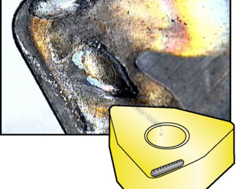
Diffusion is strongly temperature dependent, so a modest increase in cutting speed can produce a disproportionate loss of tool life. This is one reason a process may look stable during a short trial and then deteriorate quickly in production. The crater grows, weakens the land behind the cutting edge, and eventually leaves too little material to support the edge.
The corrective direction is thermal: reduce cutting speed before cutting feed blindly, improve heat removal where coolant is appropriate, choose a grade and coating designed for the workpiece and temperature, and use a freer-cutting geometry if the edge can remain strong enough. Research on uncoated cemented carbide in Ti-6Al-4V machining has identified temperature-driven diffusion as a principal mechanism under the tested conditions, while high-speed dry milling studies report abrasion, adhesion, oxidation, diffusion, and thermal-mechanical fatigue acting together.
4. Oxidation wear: the hot surface reacts with oxygen
At elevated temperature, exposed tool material can react with oxygen and form oxide products. If the oxide layer is brittle or poorly attached, chip flow and cyclic contact remove it. Fresh material is exposed, another layer forms, and the cycle repeats. Oxidation is therefore a chemical wear mechanism coupled with mechanical removal.
There is no universal temperature threshold for every carbide grade, coating, atmosphere, and contact condition. The often-quoted 700-800 degrees C range may describe some cemented-carbide situations, but it should not be treated as a machine-setting rule. Real cutting interfaces contain steep temperature gradients and areas with different access to oxygen. Oxidation may be more active near exposed contact boundaries than directly beneath a tightly contacting chip.
Dry cutting, high surface speed, long engagement, and poor heat evacuation increase the risk. Thermally stable coatings such as AlTiN or TiAlN can form protective aluminum-rich oxides under suitable conditions, but coating choice must still match the workpiece and operation. Coolant can reduce temperature in continuous turning, while intermittent or poorly directed coolant in milling may increase thermal cycling. Consistency matters more than the simple instruction to “add coolant.”
A practical comparison of the four mechanisms
Mechanism | What removes tool material | Typical clues | Conditions that often promote it | First controlled response |
Abrasion | Hard particles scratch or plough the surface | Parallel grooves, even flank land, gradual size drift | Hard inclusions, scale, recut chips, lower-to-moderate speed | Check runout and chip evacuation; test lower speed or a more wear-resistant grade |
Adhesion | Micro-welded work material tears away from the edge | Built-up edge, smeared material, irregular pits, finish changes | Ductile or chemically compatible materials, rubbing, unstable chip load | Restore real chip thickness; improve lubrication, geometry, surface finish, or speed window |
Diffusion | Atoms migrate across a hot chip-tool interface | Rake-face crater, rapid loss of edge support at high speed | High interface temperature and sustained contact | Lower speed; use a heat-resistant grade/coating and freer-cutting geometry |
Oxidation | Reactive surface film forms and is removed | Discoloration, boundary wear, flaking reaction layer | Hot exposed edge, dry cutting, long engagement | Reduce thermal load; select oxidation-resistant coating; stabilize coolant strategy |
Why the same tool can show more than one mechanism
Real cutting edges do not follow textbook boundaries. During milling, each tooth repeatedly heats in the cut and cools out of the cut. The rake face can experience adhesion near the edge, diffusion under the hottest chip contact, and oxidation near an exposed boundary. Abrasive particles can then remove a weakened coating or reaction layer.
The sequence also matters. Adhesion may strip a coating and expose the carbide. The exposed substrate then runs hotter, accelerating diffusion. A crater or flank land weakens the edge until vibration or chip impact produces visible chipping. The final fracture gets blamed, even though it was the last step rather than the first cause.
Six changes that usually produce useful tool-life gains
1. Record wear by edge and by interval
Inspect the tool before catastrophic failure. Photograph the same edge at fixed part counts or cutting-time intervals, and record flank-wear width where practical. Pair the image with spindle load, dimensions, surface finish, chip form, and coolant condition. A tool-life number without a wear record cannot explain why one trial won.
2. Change one high-leverage variable at a time
Cutting speed is strongly linked to temperature, while feed and engagement control chip thickness and mechanical load. Change speed first when the evidence points to thermal wear. Correct feed per tooth when the edge is rubbing or the chip is too thin. If speed, feed, coating, holder, and coolant are changed together, the result cannot be transferred to the next job.
3. Keep the tool cutting, not rubbing
Programmed feed is not the same as actual chip thickness. Radial chip thinning, corner slowdown, runout, tool deflection, and machine acceleration can leave one flute rubbing while another carries most of the load. Use a feed appropriate to the effective engagement, maintain a stable entry, and avoid dwell on the surface. In work-hardening alloys, rubbing creates an even worse surface for the next tooth.
4. Control heat with the whole process
Coolant is one control, not the entire strategy. Reduce unnecessary surface speed, shorten engagement where the path allows, evacuate hot chips, and choose a geometry that cuts freely. For milling, avoid an erratic coolant stream that repeatedly quenches a hot edge. For deep holes or enclosed pockets, delivery pressure and direction may matter more than tank concentration alone.
5. Match coating and substrate to the dominant risk
AlTiN/TiAlN-family coatings are commonly selected for hot, high-speed steel machining because of their thermal stability and oxidation behavior. TiCN-family coatings can provide strong wear resistance in suitable lower-temperature applications, though their use depends on the operation and workpiece. Aluminum machining often benefits from smooth, low-affinity surfaces or application-specific coatings rather than a generic high-temperature coating. The substrate still determines toughness; a hard coating cannot rescue a brittle edge in an unstable setup.
6. Set a replacement limit before the edge collapses
The cheapest possible tool cost per edge is not the same as the lowest cost per good part. Once wear accelerates, the process may consume tolerance, surface finish, cycle time, and operator attention. Establish the replacement point using a combination of wear-land measurement, dimensional drift, roughness, spindle-load trend, or validated part count. Seco notes that changing chip shape or color, rising power or vibration, and deteriorating surface finish can all indicate advancing wear.
A troubleshooting sequence for the next failed tool
What you observe | What to verify before changing tools | Likely direction |
Even flank wear on all edges, but too fast | Actual surface speed, workpiece hardness, scale, chip recutting | Reduce speed or test a more wear-resistant grade/coating |
One flute or insert wears much faster | Runout, insert seating, holder condition, spindle and setup rigidity | Correct load sharing before comparing grades |
Shiny deposit or smeared material on the edge | Feed at low-speed segments, lubrication, edge sharpness, flute/rake finish | Avoid rubbing and move away from the built-up-edge speed range |
Rake-face crater grows behind the edge | Speed, chip contact length, coolant delivery, coating compatibility | Reduce thermal load and improve hot-hardness/chemical stability |
Repeated random chips or edge fractures | Chatter, overhang, entry/exit shock, recut chips, prior crater/flank wear | Stabilize the setup and find the damage that preceded fracture |
Notch at the depth-of-cut line | Work hardening, scale, repeated depth line, oxidation near contact boundary | Vary axial depth, improve edge preparation, and review speed/coolant strategy |
Run the next trial with a baseline and a defined success criterion. For example: maintain the same cycle time, reduce average flank wear after 40 minutes of cutting, and keep surface roughness inside the drawing requirement. Tool life that doubles by slowing the machine by half is not necessarily an improvement.
What buyers should ask a tooling supplier
The useful question is not “Which grade lasts longest?” Ask what failure mode the grade is intended to control, what speed and chip-load window supports that claim, and what edge preparation was used in the reference application. Share a close photograph of the worn edge, the workpiece grade and hardness, tool diameter, operation, holder, overhang, engagement, speed, feed, coolant method, and current life. That information gives the supplier a real process to evaluate.
When HNCarbide reviews an application, the same principle applies: diagnose the dominant wear mechanism first, then compare geometry, substrate, coating, and parameters. A more expensive tool is useful only if it addresses the reason the current edge is losing material.

Conclusion
Abrasion scratches the tool, adhesion tears micro-welded junctions away, diffusion changes a hot interface, and oxidation repeatedly forms and removes reaction products. Those mechanisms overlap, so the final broken edge is rarely the whole story.
Start with the wear pattern, add the process history, and run one-variable trials with a clear replacement limit. That approach turns discarded tools into process data and gives a shop a realistic path to longer, more predictable tool life.