Four Common Milling Cutters and How to Choose the Right Tool
Table of Contents
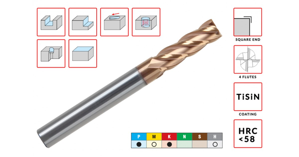
Choosing a milling cutter by appearance alone is an expensive habit. Two tools may fit the same holder and cut the same material, yet produce very different cycle times, chip loads, surface finishes, and tool life. The useful question is not simply, “Which cutter removes metal?” It is, “Which cutter creates this feature with the least risk and the fewest operations?”
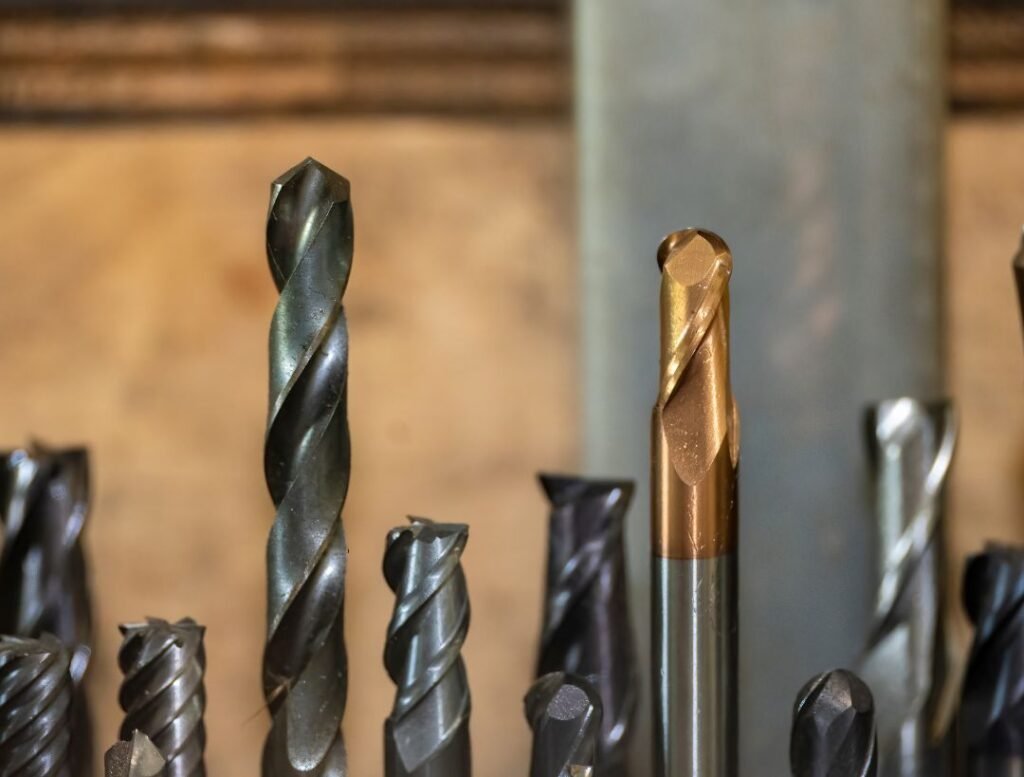
For many CNC shops, four cutter families cover a large share of everyday work: square end mills, ball nose end mills, face mills, and chamfer mills. Each has a clear strength, but each also has a working envelope that is easy to overlook. This guide explains where the four cutters fit, what to check before ordering, and when a seemingly reasonable choice creates avoidable problems.
Quick Comparison: Match the Cutter to the Feature
Start with the geometry on the drawing. A tool should be selected around the feature it must generate, not around the cutters that happen to be free in the tool cabinet.
Cutter type | Best suited to | Main strength | Common limitation |
Square end mill | Slots, pockets, shoulders, side walls, 2D contours | Versatile axial and radial cutting | Full-width slotting can overload the tool and restrict chip evacuation |
Ball nose end mill | Molds, dies, fillets, freeform surfaces, 3D finishing | Smooth tool contact on changing surface angles | Cutting speed approaches zero at the tool center |
Face mill | Broad flat surfaces, datum faces, large plates and housings | High metal-removal rate across a wide path | Requires sufficient spindle power, rigidity, and workholding |
Chamfer mill | Edge breaks, bevels, deburring, countersinks, spotting | Completes several edge-detail operations with one tool | Programmed depth directly changes chamfer width |
This comparison is a starting point. Workpiece material, machine stability, tool overhang, coolant delivery, and required finish still affect the final choice.
1. Square End Mills: The General-Purpose Choice
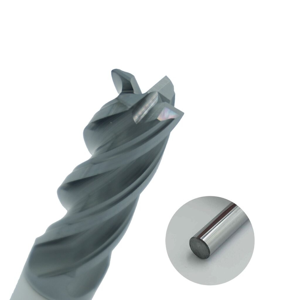
A square end mill has cutting edges around its circumference and across the end. That combination allows it to machine a wall and a floor, making it the standard tool for pockets, slots, steps, shoulders, and contours. It can feed radially, ramp into a pocket when the geometry permits, and in some designs perform limited axial entry.
The term “general purpose” does not mean one end mill is suitable for every job. The most visible selection variable is flute count. Fewer flutes leave more room for chips; more flutes provide additional cutting edges and a stronger core. A two- or three-flute geometry is therefore common in aluminum and in operations where chip volume is high. Four or more flutes can support higher feed rates and stable finishing in steels, provided the flute space remains adequate for the chip load.
Modern roughing strategies complicate the old rule that fewer flutes always belong in roughing. With a small radial engagement and controlled toolpath, a multi-flute carbide end mill can remove material efficiently because the cut produces thinner chips and leaves space for a higher tooth count. The toolpath, flute geometry, and coolant or air delivery must be considered together.
What to check before selecting an end mill
Use the shortest practical tool. Extra reach reduces stiffness quickly and makes chatter, wall taper, and edge chipping more likely. Match the corner style to the feature: a sharp corner creates a square floor-to-wall intersection but is weaker than a corner-radius design. Check whether the tool is center cutting before planning a plunge, and do not assume every end mill can enter the material vertically.
For deep slots, chip evacuation may become the limiting factor before spindle power does. A lighter radial cut, trochoidal path, pecking strategy, or air blast can be more productive than forcing a full-width slot at an aggressive feed.
2. Ball Nose End Mills: Built for 3D Surfaces
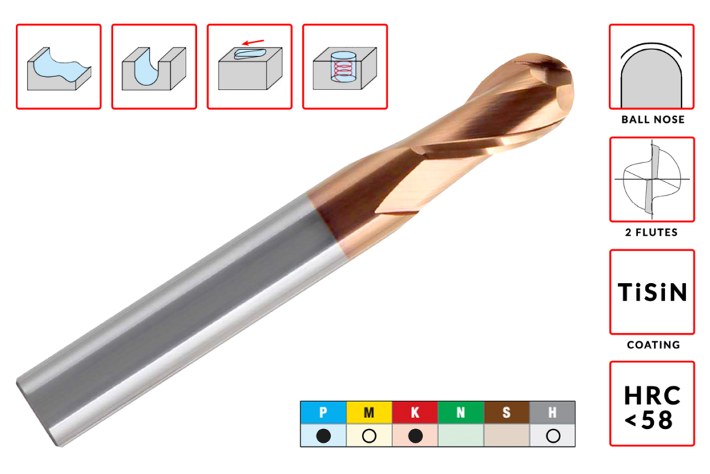
A ball nose end mill replaces the flat end with a hemispherical cutting profile. It is the natural choice for mold cavities, dies, turbine-style contours, impellers, fillets, and other surfaces whose slope changes continuously. During finishing, the cutter follows closely spaced toolpaths and leaves a series of small cusps, or scallops. A smaller stepover reduces scallop height and improves the surface, but it also increases cycle time.
The most important limitation is at the center of the ball. Surface speed falls as the effective cutting diameter becomes smaller and reaches almost zero on the tool axis. If the tool is held nearly vertical against a flat or shallow surface, the center tends to rub rather than shear cleanly. This can raise heat, accelerate wear, and damage finish.
Where the part and machine permit, tilting the tool or using a five-axis lead angle moves contact away from the center. On a three-axis machine, a suitable toolpath and a smaller ball nose may improve contact, though the added passes must be weighed against cycle time. Barrel and lens cutters may be more efficient for some large, shallow freeform surfaces, but ball nose tools remain the flexible choice for tight details and mixed geometry.
Roughing and finishing are different jobs
A ball nose tool can remove stock, but it is usually most valuable in semi-finishing and finishing. Leave a consistent allowance after roughing so the finish tool sees a stable load. Uneven stock can deflect a small cutter and create visible transitions even when the programmed toolpath is smooth.
Runout also matters. On small-diameter ball nose tools, a few microns of runout can force one flute to do most of the cutting. A clean holder, controlled gauge length, and measured runout often deliver more benefit than a small increase in programmed feed.
3. Face Mills: Efficient Machining of Broad Flat Surfaces
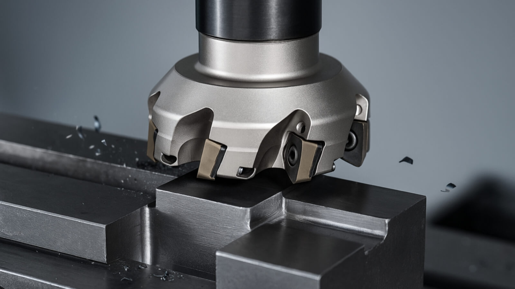
A face mill carries multiple inserts around a comparatively large cutter body. Its diameter lets it cover a broad path, which is why it is commonly used to establish datum faces on plates, housings, castings, and other large components. Indexable inserts also make the system economical: the shop replaces or indexes the cutting edges rather than discarding the whole cutter.
Bigger is not automatically faster. Cutter diameter should suit the workpiece width, machine power, spindle interface, and setup rigidity. A cutter that is too large can demand more torque, amplify runout, and excite vibration. It may also spend too much of each revolution outside the cut, creating an unfavorable entry and exit condition.
Insert pitch is another practical decision. A coarse-pitch body provides larger chip spaces and keeps fewer teeth engaged at once, which can help on lower-power machines, unstable setups, and long-chipping materials. A close-pitch cutter brings more edges into the cut and can raise productivity in stable conditions, but it also increases power demand and leaves less room for chips.
Finish depends on more than feed per tooth
Axial runout between inserts can cause one edge to sit lower and produce the final surface alone. Clean insert pockets, correct screw torque, sound cutter-body condition, and a rigid arbor are essential. Wiper inserts can improve finish at productive feeds, but they cannot compensate for a loose fixture or a spindle in poor condition.
For many face-milling operations, an off-center cutter path encourages a favorable cutting action and helps avoid repeated impact at the least stable point of engagement. Exact positioning depends on cutter geometry and the insert maker’s recommendations.
4. Chamfer Mills: Small Features with a Large Effect on Part Quality
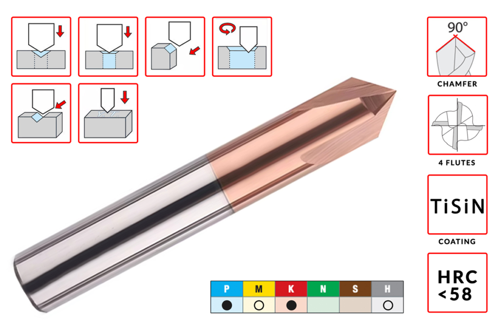
Chamfer mills are often treated as secondary tools, yet a poor edge can stop an otherwise acceptable part at inspection or assembly. Sharp edges are difficult to handle, burrs interfere with fit, and an incorrect countersink prevents a fastener from seating properly. Bringing edge finishing into the CNC cycle also reduces variation from manual deburring.
Common included angles include 60°, 90°, and other application-specific geometries. Tool catalogs do not always describe angles in the same way, so confirm whether the value is an included angle or the angle per side. A “45-degree chamfer” on a drawing is commonly produced with a 90-degree included-angle cutter.
Chamfer width is controlled by axial position. A small Z-axis error therefore becomes a visible width error around the part. Tool-tip condition, runout, part location, and burr direction all matter when the tolerance is tight. For a pointed tool, programming directly to an assumed mathematical tip can introduce error because the real tip may have a small flat or radius. Set and program the actual tool geometry.
A chamfer mill may also bevel, deburr, countersink, or spot a hole, but not every design is center cutting. Verify the cutter geometry before using it for axial entry. When spotting before drilling, the relationship between the spotting angle and drill-point angle affects how the drill engages.
Selection by Material and Shop Condition
The cutter family defines the feature; substrate, coating, flute form, and edge preparation determine how well the tool handles the material. The table below summarizes the main selection focus rather than prescribing universal parameters.
Workpiece or condition | Tool-selection focus | Practical reason |
Aluminum and other non-ferrous alloys | Sharp polished edges, generous flute space, low-affinity coating or uncoated geometry | Reduces built-up edge and clears large chip volume |
Carbon and alloy steels | Balanced edge strength, wear-resistant coating, stable flute count | Supports predictable wear and productive cutting speeds |
Stainless steel | Positive geometry, controlled engagement, effective coolant delivery | Limits work hardening, heat, and edge build-up |
Cast iron | Abrasion-resistant grade, suitable edge preparation, dust/chip control | Handles abrasive wear and interrupted surfaces |
Hardened steel | Rigid setup, short reach, heat-resistant carbide/coating, finishing allowance | Reduces deflection and manages high cutting-zone temperature |
Thin walls or weak workholding | Low cutting force, light radial engagement, sharp geometry | Prevents distortion, chatter, and part movement |
Cutting data should begin with the tool supplier’s range and then be adjusted for radial engagement, axial depth, overhang, machine capability, and setup. Copying speed and feed values from a different cutter diameter or toolpath is rarely a controlled test.
A Practical Tool-Selection Checklist
Before releasing the program, connect the drawing requirement to the complete cutting system.
Question | Why it matters |
What feature must be generated? | Separates pocketing, 3D profiling, facing, and edge finishing immediately |
What are the material and hardness? | Drives carbide grade, coating, edge preparation, and chip-space requirements |
Is the operation roughing, semi-finishing, or finishing? | Changes allowance, geometry, flute count, and surface-finish priority |
What is the deepest reach and minimum internal radius? | Establishes tool diameter, neck length, and the shortest safe overhang |
How rigid are the machine, holder, and workholding? | Determines whether the planned engagement and tooth count are realistic |
How will chips leave the cut? | Prevents recutting, built-up edge, and thermal damage |
What finish and edge tolerance are required? | Sets stepover, wiper needs, runout limits, and inspection method |
Can one tool safely complete more than one feature? | May reduce tool changes without compromising geometry or reliability |
Common Selection Errors and Corrective Actions
Symptom | Likely selection or application issue | Corrective direction |
Packed flutes or welded chips in a slot | Too many flutes, excessive engagement, weak chip evacuation | Increase chip space, reduce engagement, or improve air/coolant delivery |
Poor finish in a shallow 3D area | Ball nose cutting near its center | Change tool angle or path; move contact away from the center where possible |
Chatter during face milling | Cutter too large, too many inserts engaged, excessive overhang, or weak fixture | Use a smaller/coarser-pitch cutter and improve system rigidity |
Uneven face-milled pattern | Insert axial runout, damaged pockets, or spindle/arbor error | Clean and inspect pockets, torque correctly, and measure runout |
Chamfer width varies around the part | Part location, runout, tip geometry, or Z-depth error | Probe the part, verify actual cutter geometry, and control tool length |
Premature corner chipping on an end mill | Sharp corner under heavy load or unstable entry | Use a corner radius and smoother engagement strategy when the drawing allows |

Final Takeaway
Square end mills, ball nose end mills, face mills, and chamfer mills cover a large portion of routine CNC milling, but they are not interchangeable shortcuts. The square end mill is the flexible choice for prismatic features. The ball nose end mill controls freeform surfaces. The face mill creates broad flat faces efficiently. The chamfer mill turns edge finishing into a repeatable machining operation.
Good selection begins with the feature, then accounts for material, chip flow, rigidity, reach, and finish. When a standard geometry cannot meet the reach, profile, or cycle-time requirement, a custom cutter may remove operations and stabilize production. HNCarbide supports carbide milling-tool selection and application-specific tool development for shops that need a more reliable fit between the drawing and the process.