 Skip to content
Flat End Mills Explained: Geometry, Uses and Selection Tips
Table of Contents
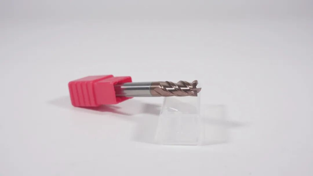
A pocket can have a clean floor and still fail inspection because the wall tapers, the bottom corner is oversized, or chatter marks spoil a sealing surface. Choosing a flat end mill is straightforward only when the drawing, tool geometry and cutting strategy agree.
Also called a square end mill, this cutter is a practical choice for flat floors, slots and vertical shoulders. Its usefulness comes from a combination of peripheral cutting edges and end cutting edges. Getting consistent results requires more than choosing a diameter and assuming that four flutes will handle everything.
This guide explains where flat end mills fit, how to read their specifications, and which selection decisions prevent avoidable problems in CNC machining and mold work.
What a flat end mill can machine
The outside edges cut the walls of a feature, while the end edges generate its floor. At their intersection, a square end mill has a nominal 90-degree corner. The actual edge may include a small hone or protective corner treatment, so a product description alone is insufficient when the drawing specifies a very small allowable root radius.
The term “flat” describes the machining profile. It does not mean that the entire end face is a flat, rubbing surface; relief behind the cutting edges provides clearance. Square, corner-radius and ball-nose tools have different end profiles, each suited to particular feature shapes.
Tool profile | Useful applications | Geometric limitation |
Flat or square end | Flat pocket floors, slots, vertical shoulders and side profiling | Sharp corner is vulnerable to chipping; check the actual edge treatment |
Corner radius or bull nose | Pocket roughing and shoulder milling where a root fillet is allowed | Leaves a floor-to-wall radius corresponding to the tool corner |
Ball nose | Sculpted surfaces, mold contours and curved transitions | Leaves scallops between passes on flat areas; effective cutting speed falls near the tip |
A flat end mill can produce a nearly square floor-to-wall junction. It cannot produce a zero-radius internal corner when viewed from above. A rotating cylindrical cutter always leaves a radius in that plane.
For example, a 10 mm cutter has a geometric minimum internal radius of 5 mm. Selecting it for a finished 5 mm pocket corner also creates a demanding engagement condition. A smaller cutter gives the toolpath room to turn and control engagement. This is a separate issue from the tiny corner radius at the cutter’s tip.
Read the dimensions before choosing the tool
Diameter sets the feature access and influences stiffness, but reach often determines whether a tool will work in practice. A cutter that fits the pocket opening may still collide with a wall once the holder or shank descends.
Length of cut is the usable fluted length. Overall length is the full tool length. Reach describes the distance available below the shank or another specified reference, depending on the manufacturer’s drawing. Overhang is the actual unsupported projection from the holder in the assembled setup. These dimensions should not be treated as interchangeable.
Specify only the cutting length and reach the operation needs. Excess flute length removes supporting material from the tool, while excess overhang increases deflection. For deep features, a relieved neck can provide clearance without extending the flutes through the entire reach. The reduced neck still limits stiffness; it does not make a long tool behave like a short one.
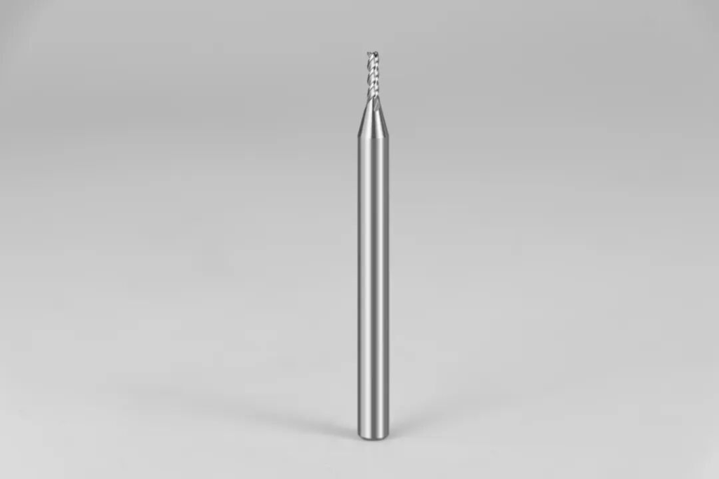
Before releasing a purchase order, check the cutter diameter tolerance, shank size and maximum permitted corner treatment. A replacement tool that is nominally the same diameter can still require a different offset, holder or finishing allowance.
Choose flute count around engagement and chip space
Flute count affects how often an edge enters the cut and how much space remains for chips. Two- and three-flute cutters are common starting points for aluminum, especially in slots where chips have limited escape paths. Four-flute designs are widely used in steels. Higher flute counts can suit light radial engagement and finishing, provided the tool geometry and machine support the intended operation.
These are starting points, not material rules. A high-flute cutter designed for dynamic milling is a different proposition from a general-purpose cutter pushed through a full-width slot.
Workpiece and operation | Starting point to evaluate | What to verify |
Aluminum pocketing or full-width slots | Aluminum-specific 2- or 3-flute geometry | Chip space, sharp edges, lubrication and chip evacuation |
Carbon steel or prehardened mold steel | Application-rated 4-flute tool | Hardness range, allowable engagement and coating |
Stainless steel profiling | Stainless-specific geometry, often 4 or more flutes | Edge strength, chatter behavior and a feed that avoids rubbing |
Hardened steel finishing | Hardened-steel series, often with multiple flutes | Actual hardness rating, runout and small-engagement cutting data |
Plastics or copper alloys | Material-specific cutter | Polymer or alloy behavior, burr control, heat and chip form |
Do not select a high-flute tool solely to obtain a better finish. A clean edge, low runout and stable workholding matter as much as the number of teeth. If one flute protrudes farther than the others, it can carry a disproportionate share of the cutting load.
Increasing flute count also changes programmed feed. At a fixed spindle speed and feed per tooth, more teeth require a higher feed rate. If machine feed stays unchanged, feed per tooth falls. An excessively light chip can lead to rubbing rather than the finish improvement the buyer expected.
Helix angle and coating need an application match
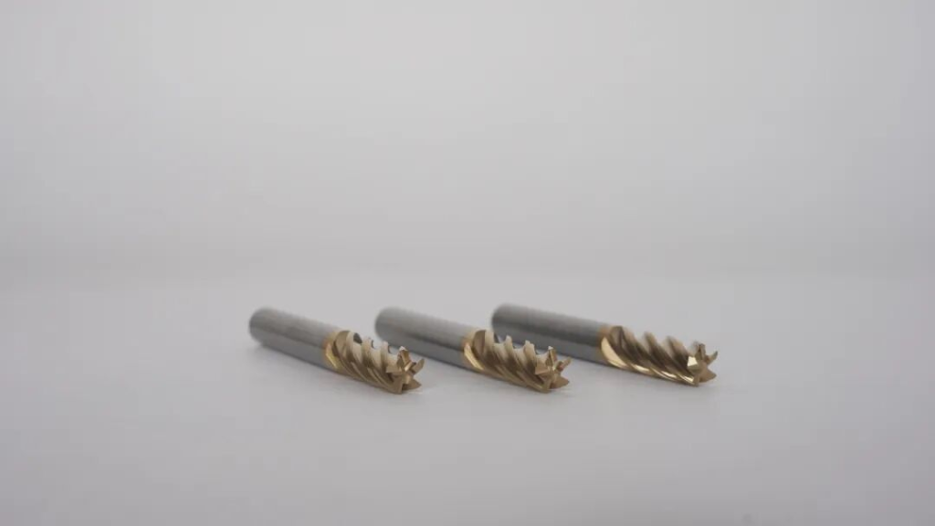
Common helix angles include values around 30 to 45 degrees, but there is no single angle that is best for every flat end mill. A higher helix changes the direction of cutting forces and the progression of edge engagement. It can help in some finishing applications while increasing axial pull on the tool or workpiece. Variable helix and unequal flute spacing are options to evaluate when chatter limits production.
For a thin wall, inspect both surface finish and dimensional movement after unclamping. A cutter that sounds smooth can still deflect the wall. For a deep slot, consider chip space and tool strength before choosing a high helix on the assumption that it will automatically clear chips faster.
Coating selection starts with the workpiece and cutting conditions. AlTiN-based and AlCrN-based systems are common in suitable steel-cutting applications, but their performance depends on the specific coating structure and tool design. Coating color cannot reliably identify chemistry or temperature capability.
For aluminum, polished uncoated carbide and coatings designed to resist adhesion are established options. TiB2, ZrN and some DLC systems are candidates, depending on alloy and application. DLC means diamond-like carbon; it is not the same as crystalline CVD diamond. Abrasive, high-silicon aluminum may call for a different wear solution from a wrought aluminum alloy.
Center cutting does not remove entry limits
A center-cutting end mill has end geometry that can remove material at the tool axis. This makes axial entry possible for tools rated for that use. It does not establish a safe plunge feed, depth or coolant requirement by itself.
Cutting speed approaches zero at the rotational center, and chip evacuation becomes difficult during a straight plunge. Helical entry or a shallow linear ramp is often preferable where the feature and tool allow it. Use the manufacturer’s maximum ramp angle and minimum helical-entry diameter, with the correct distinction between tool-center path diameter and the resulting hole diameter.
A non-center-cutting tool should enter through a suitable pre-machined opening or from an open edge. Do not assume that it can ramp into solid stock merely because the motion is diagonal. Any approved ramping operation depends on the specific end geometry and clearance.
For a closed pocket, settle the entry method before ordering the cutter. A tool that cuts the walls well may be unsuitable for the only entry path available on the part.
Make roughing productive without sacrificing the corner
A flat end mill is efficient on many prismatic features because its profile suits the required walls and floors. There is no universal material-removal multiplier compared with a ball nose cutter. Productivity depends on engagement, feed, usable edge length, power and stability. End shape alone also does not establish which tool has the highest bending stiffness.
For a steady rectangular cut, material removal rate is axial depth multiplied by radial width multiplied by feed rate. As an arithmetic example, 5 mm axial depth, 2 mm radial width and 1,000 mm/min feed give 10,000 mm³/min, or 10 cm³/min. These values illustrate the calculation; they are not cutting recommendations.
The practical question is whether that rate can be maintained through the whole path. Engagement rises as a cutter enters a tight internal corner, so a stable straight cut does not prove that the corner move is acceptable. Use an engagement-aware path and appropriate corner feed control. Leave a controlled allowance for finishing when the drawing demands consistent wall position or floor quality.
If the drawing permits a small floor-to-wall fillet, consider a corner-radius cutter. Rounding the sharp intersection can improve edge durability, but there is no general basis for promising an 80 percent stress reduction or doubled life. The acceptable radius comes from the part requirements. Do not assume that later polishing can remove a fillet without changing dimensions or fit.
Diagnose the setup before replacing the cutter
When a flat end mill chips or leaves a poor finish, inspect the failed edge and the point in the cycle where the problem begins. A failure during entry calls for a different response from wear that develops uniformly over a long batch.
Observed problem | Possible cause to investigate | Useful first check |
Corner chips during pocket entry | Entry load, chip congestion or an unsupported plunge strategy | Confirm entry approval and inspect chip escape space |
Wall taper or inconsistent size | Tool or workpiece deflection, runout or wear | Measure projection and runout; compare roughing and finishing loads |
Chatter near internal corners | Rising engagement or insufficient stiffness | Review corner toolpath and feed; shorten overhang where possible |
Aluminum deposits on the edge | Adhesion, chip recutting or unsuitable geometry | Check lubrication delivery and use aluminum-specific cutting data |
Lines or steps across the floor | Tram error, deflection, worn end edges or pass mismatch | Inspect spindle alignment and end-edge condition |
Record a baseline before changing several variables. Note the tool code, holder, projection, material grade and cutting data, then compare the result after a controlled adjustment. This gives the next operator a usable process record and gives the supplier evidence for a recommendation.
Verify the first part before running the batch
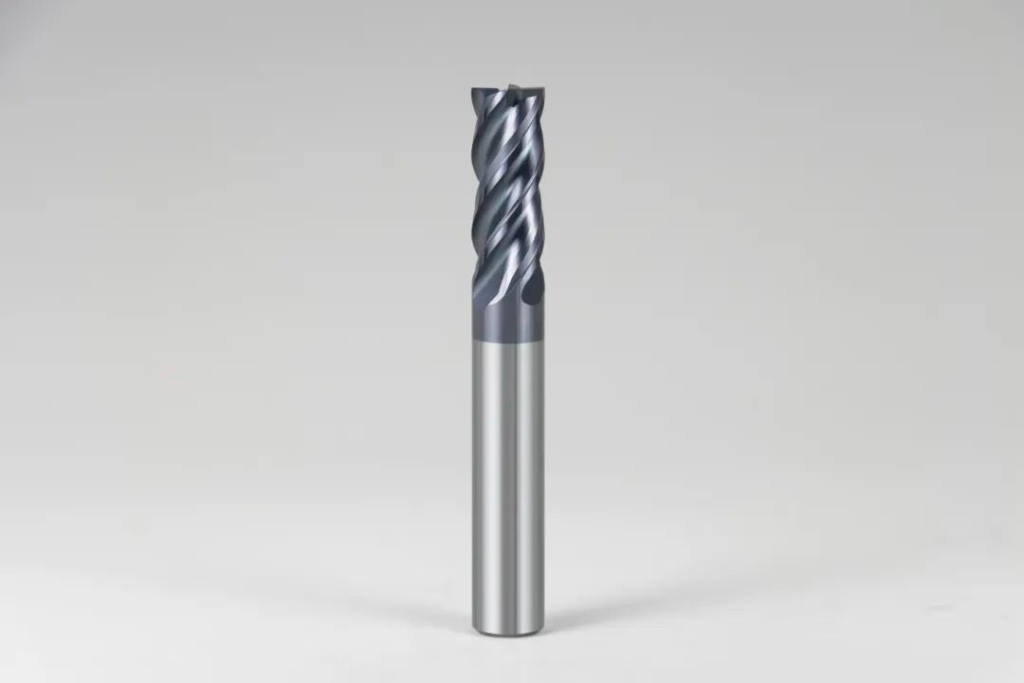
Use the first part to check whether the selected tool and programmed path produce the required geometry. Measure the pocket width and depth, then inspect the floor-to-wall junction against the drawing. A clean-looking floor does not establish that the wall is straight or the corner is within tolerance.
Where wall taper matters, compare measurements at different heights using a suitable inspection method. Check thin or flexible parts after unclamping as well as in the fixture. Record the tool offset and the measured result before making a correction; otherwise, an offset change can hide a deflection problem that returns as cutting conditions change.
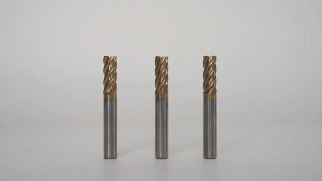

Inspect the cutting edges after the trial, especially the end corners. Note whether damage appears during entry, at a tight turn or after sustained cutting. Once dimensions and finish are acceptable, retain the setup details and establish inspection intervals for the batch. Track dimensional drift alongside edge condition so that a worn tool is replaced before it produces rejected parts.
Choose around the feature and the process
A flat end mill is a sensible starting point for flat floors and square shoulders. The reliable choice is the one with enough chip space, the shortest practical reach and an entry method suited to its geometry. Check the drawing’s corner limits before deciding between a square edge and a small corner radius.
Before moving into production, verify the first part and record the setup that produced it. A repeatable process depends on controlling projection, engagement and tool condition throughout the batch, not simply choosing a cutter that passes the first inspection.





