
Feed per Tooth in CNC Milling: How to Balance Surface Finish and Tool Life
Table of Contents
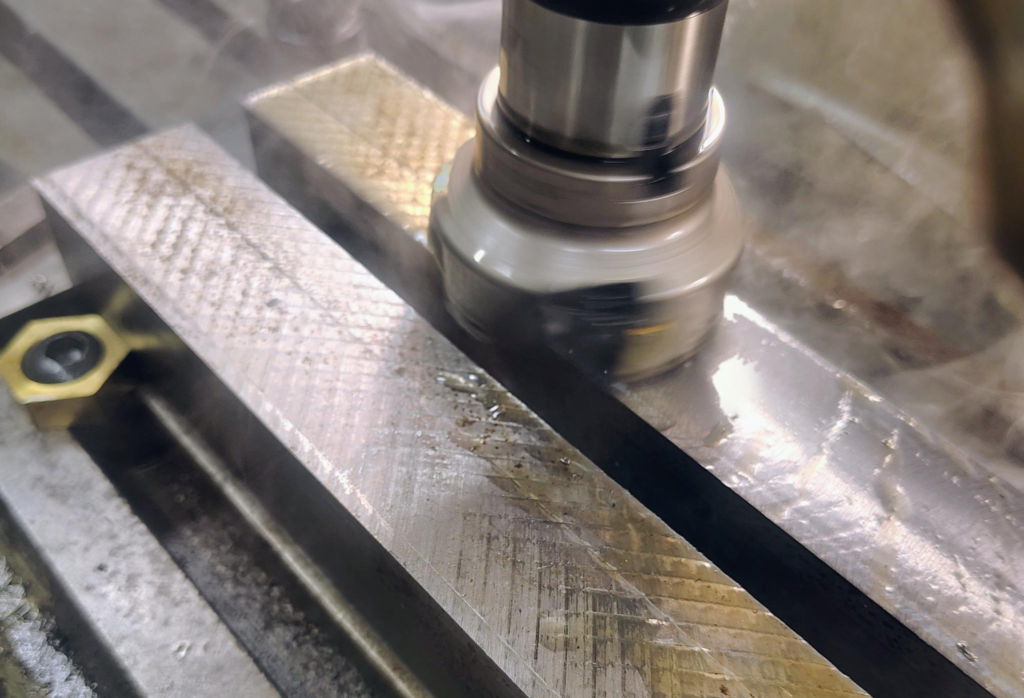
In milling, feed per tooth looks like a small number. It is usually written as fz or chip load per tooth, and it may be only 0.03 mm, 0.08 mm, or 0.15 mm per cutting edge. On the shop floor, though, that number can decide whether a part comes off the machine cleanly or needs polishing, whether a carbide end mill runs a full batch or fails halfway through it.
Many operators adjust feed by feel. If cycle time is too long, they push it up. If the surface looks rough, they pull it down. That instinct is not wrong, but it misses the real tradeoff. Feed per tooth controls chip thickness. Chip thickness controls cutting force, heat, rubbing, surface marks, and the way the edge wears.
The tricky part is that surface finish and tool life do not always want the same answer. A lower fz usually improves the theoretical finish, but if it drops below the minimum chip thickness, the tool starts rubbing instead of cutting. A higher fz improves productivity and can help the edge take a real chip, but it also raises force and can damage the cutting edge. The useful setting is not “as low as possible” or “as high as the machine allows.” It is the range where the tool cuts cleanly, the surface meets the drawing, and wear stays predictable.
What feed per tooth really means
Feed per tooth is the linear distance the workpiece or cutter advances for each flute or insert as it engages the material. In milling formulas, it links spindle speed, number of teeth, and table feed:
`feed rate = spindle speed x number of teeth x feed per tooth`
That formula is simple. The cutting behavior behind it is not. If a 4-flute end mill runs at the same RPM as a 2-flute end mill and both use the same programmed feed rate, the 4-flute tool has half the chip load per tooth. The machine may look busy, but each edge may be taking a thin, hot, unstable chip.
This is why fz should be treated as an edge-load value, not just a feed-rate value. It tells you how hard each tooth is working. It also helps explain why the same feed rate can be fine with one cutter and destructive with another.
Feed per tooth and surface finish
The visible surface left by milling is not perfectly flat. It contains small cusps, tool marks, and microscopic deformation left by each cutting edge. Tool runout, vibration, built-up edge, material tearing, and machine condition all influence the final result. Still, feed per tooth is one of the first parameters to check when roughness changes.
From a geometry point of view, a larger chip load leaves a larger residual height between tool passes. With a corner radius or ball-nose contact, the theoretical cusp height rises roughly with the square of feed. In plain shop language: a small increase in fz can make surface roughness increase much faster than expected.
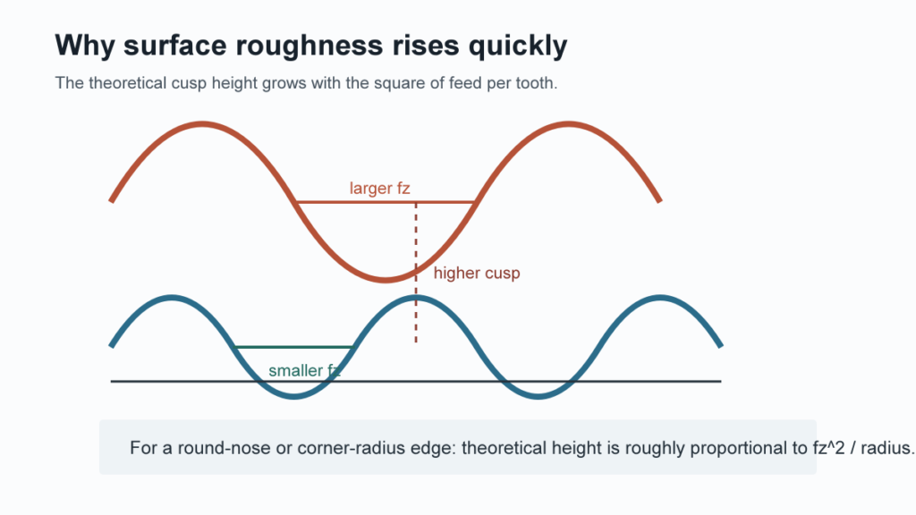
This is why finishing passes normally use a lower fz than roughing passes. The tool removes less material per edge, the feed marks become finer, and the cutter has a better chance of leaving a smooth wall or floor. A larger nose radius or corner radius can also reduce theoretical cusp height, which is one reason finishing inserts often use a suitable radius rather than a very sharp corner.
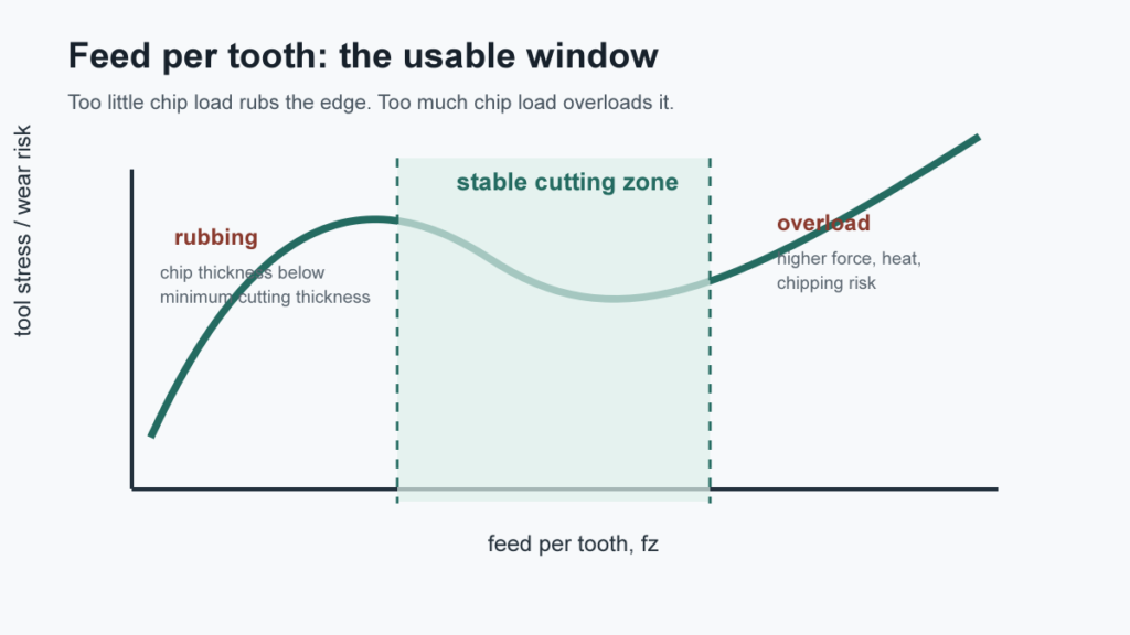
There is a limit. When the feed per tooth is too low, the cutting edge may not bite into the workpiece. Instead of shearing the material, it slides, presses, and ploughs. The surface may look shiny at first, but the process is inefficient and hot. In stainless steel, titanium, and nickel alloys, that rubbing can also encourage work hardening. Once the surface hardens locally, the next tooth enters a worse cut.
For finishing, the practical rule is to go low enough to meet roughness requirements, but not so low that chips disappear. A stable finishing cut should still make a real chip, even if that chip is fine.
Feed per tooth and tool life
Tool life is more complicated than surface finish. If fz is too high, the reason for short life is easy to see. Each tooth removes a thicker chip. Cutting force rises. The edge sees more mechanical load. In interrupted milling, that load hits the edge again and again, so chipping becomes more likely. Heat also increases, especially when chip evacuation, coolant, or coating choice is poor.
High fz can show up as rapid flank wear, crater wear on the rake face, coating flaking, corner chipping, or sudden breakage. The exact failure mode depends on the material, tool geometry, engagement, and setup rigidity. A roughing cutter in aluminum may fail from chip welding and overload. A carbide end mill in hardened steel may chip because the edge load is too high for the radius and coating.
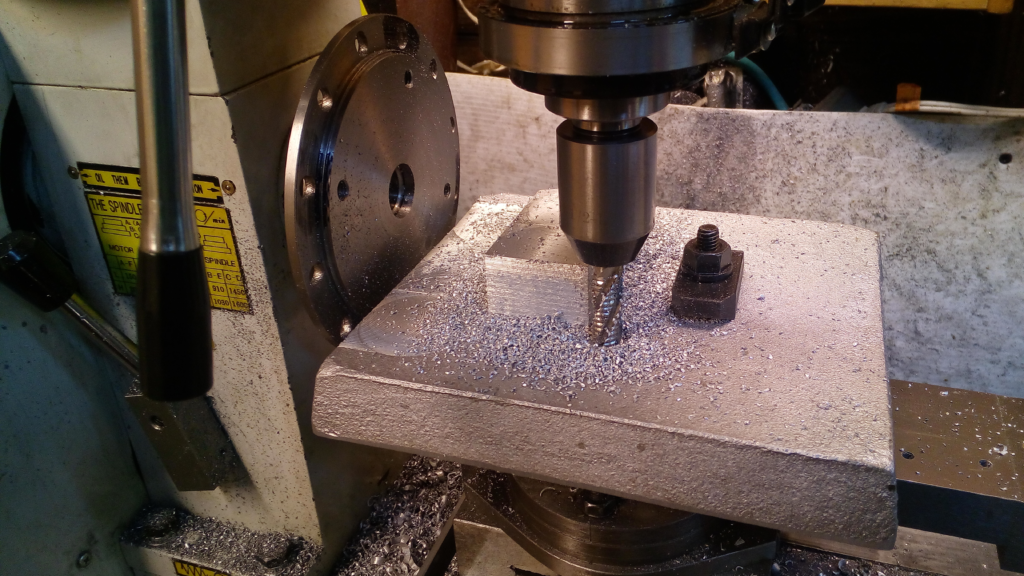
Low fz has a different failure pattern. It often looks less dramatic, so shops miss it. The tool does not break immediately. It just loses sharpness too quickly. When chip thickness falls below the minimum cutting thickness, the edge rubs and ploughs. More contact time goes into friction, not chip formation. Heat stays near the cutting edge and the finished surface. Flank wear can grow even though the programmed feed feels conservative.
That is the trap: reducing fz to “save the tool” can shorten tool life if the tool stops cutting properly.
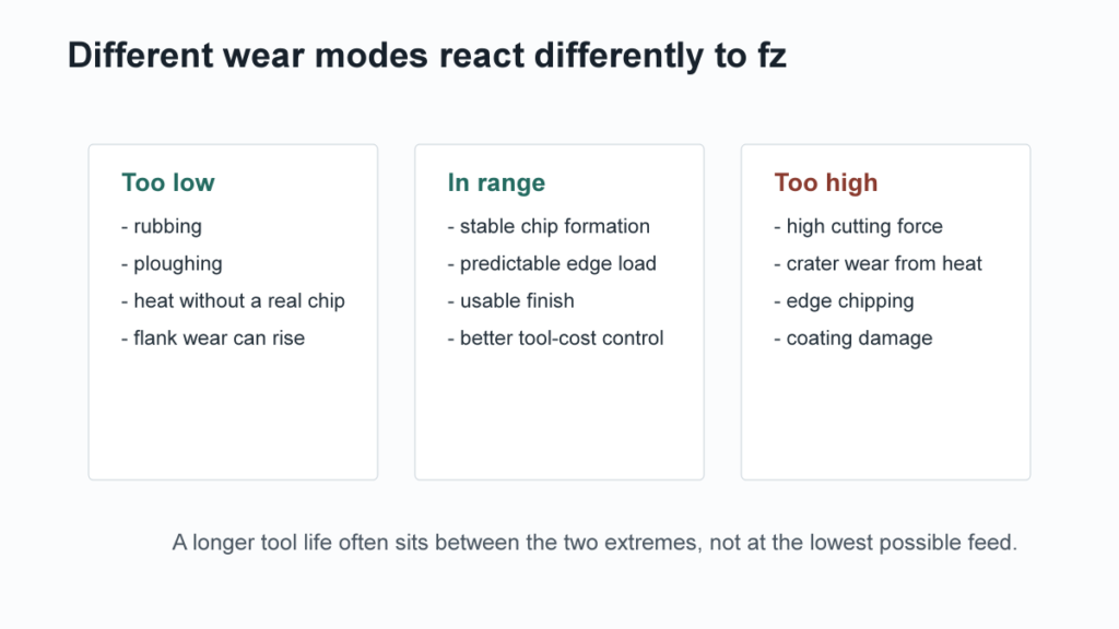
The sweet spot is a working range, not a magic number
There is no universal fz value for milling. A 6 mm carbide end mill finishing hardened steel, a 12 mm rougher slotting aluminum, and a face mill cutting cast iron do not belong in the same feed table. Even within one material, the right setting changes with radial engagement, axial depth, tool overhang, coolant, coating, edge prep, and machine rigidity.
It is better to think in ranges.
At the low end, fz must stay above the minimum chip thickness for that tool and material. The tool should cut instead of burnishing the surface. At the high end, fz must stay below the point where cutting force, spindle load, vibration, chip packing, or edge damage becomes unacceptable. The overlap between those limits is the real process window.
For production work, that window is worth proving with measurement. A small test can compare surface roughness, spindle load, chip shape, and flank wear at two or three fz values. The best answer is often not the lowest roughness number. It is the value that holds the required Ra while giving a stable wear curve and acceptable cycle time.
Practical starting points by operation
The table below is not a replacement for a tool supplier’s data. It is a way to decide which direction to move when adjusting a process.
Operation | Feed per tooth direction | Main goal | What to watch |
Rough milling | Use a higher fz within tool and machine limits | Material removal rate and stable chip formation | Spindle load, vibration, chip evacuation, edge chipping |
Semi-finishing | Use a moderate fz | Leave consistent stock for finishing | Wall deflection, tool marks, heat, tool runout |
Finish milling | Use a lower fz, but keep a real chip | Surface roughness and dimensional accuracy | Rubbing, built-up edge, work hardening, poor chip formation |
Thin-wall milling | Start conservative and reduce radial load before reducing fz too far | Limit part deflection | Chatter, spring-back, tapered walls |
High-efficiency milling | Keep fz high enough for chip thinning compensation | Productive cutting at low radial engagement | CAM engagement spikes, corner overload, heat |
One common mistake is lowering feed when the real problem is radial engagement or tool overhang. If a wall chatters, cutting fz in half may only turn cutting into rubbing. A shorter tool, smaller radial depth, better holder, or a finishing tool with more rigidity may fix the problem more cleanly.
Material changes the lower limit
Minimum chip thickness matters in every material, but some materials punish low feed more severely.
Aluminum is forgiving in cutting force, but it can form built-up edge if the tool rubs or the chip is too thin. A polished flute, sharp edge, and enough chip load usually work better than a timid feed that smears the surface.
Stainless steel and titanium need more care. Both can work harden when the edge rubs. A feed that looks gentle can create a hardened skin, then the next tooth meets a tougher surface. Tool wear rises and surface finish becomes inconsistent.
Nickel-based alloys such as Inconel-type materials generate heat and place high pressure on the edge. Too much fz can chip the tool, but too little fz can also concentrate heat at the edge. The process window is narrow, so small controlled tests are more useful than broad rules.
Workpiece material | Feed selection focus | Risk if fz is too low | Risk if fz is too high |
Aluminum alloys | Maintain chip thickness and prevent built-up edge | Smearing, built-up edge, rubbing heat | Chip packing, poor finish, cutter overload in slots |
Carbon and alloy steel | Balance productivity, finish, and edge load | Rubbing, heat, early flank wear | Higher force, vibration, edge chipping |
Stainless steel | Avoid rubbing and work hardening | Work-hardened surface, notch wear, unstable finish | Heat, tool deflection, rapid wear |
Titanium alloys | Keep cutting positive and heat controlled | Rubbing heat, surface damage, short edge life | High force, edge chipping, thermal damage |
Nickel alloys | Use a narrow, tested process window | Heat at the edge, rubbing wear | Crater wear, chipping, coating breakdown |
How to adjust fz without guessing
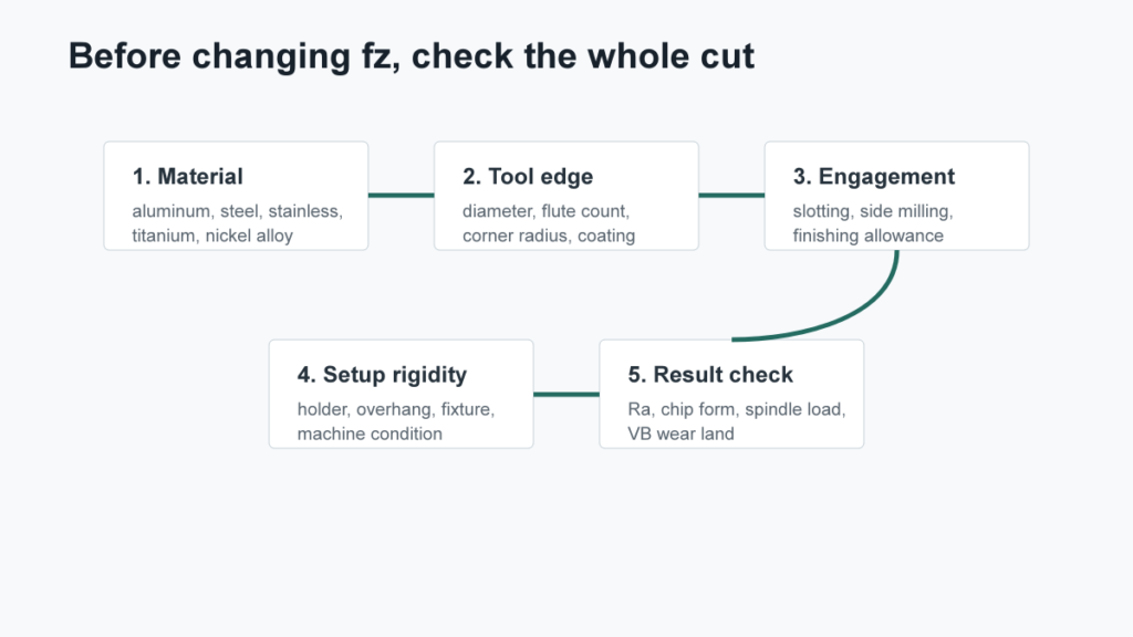
Start from the cutter manufacturer’s recommendation when available, then adapt it to the cut. Catalog chip-load values usually assume a reasonable setup, suitable holder, correct coolant, and a defined engagement range. A long-reach tool in a small machine should not be pushed like a stub end mill in a rigid machining center.
If surface roughness is too high, first look at the pattern. Even feed marks usually point toward geometry and feed. Random torn marks may point toward built-up edge, vibration, material tearing, or chip recutting. If the surface shows chatter, reducing fz alone may not solve it. If the finish has regular scallops, a lower fz or larger tool radius may help.
If tool life is poor, inspect the worn edge instead of changing numbers blindly. Flank wear with a polished, rubbed land suggests too little chip thickness or too much contact. Chipped edges suggest too much force, unstable engagement, runout, or a weak edge. Crater wear points toward heat and chip flow on the rake face. Each failure mode asks for a different response.
Troubleshooting feed per tooth problems
Symptom | Likely fz-related cause | Practical correction |
Surface looks rough with clear, regular feed marks | fz is too high for the finish requirement or tool radius | Reduce fz, use a larger corner radius where allowed, or add a light finishing pass |
Surface looks smeared or shiny but tool wears fast | fz may be below minimum chip thickness | Increase fz slightly and check whether chips form cleanly |
Edge chips during roughing | fz, engagement, or interrupted load is too high | Reduce fz or radial engagement, improve entry strategy, check runout |
Tool life is short even at low feed | Rubbing, heat, or work hardening may dominate | Raise fz into a real cutting range, improve coolant or air blast, inspect edge wear |
Finish changes across the batch | Tool wear is moving the process out of range | Track VB wear, replace tools by measured condition, not only by part count |
A practical way to set the final number
For a new job, do not begin by chasing the perfect fz. Begin by defining the acceptable result. What Ra is required? How much tool life is needed to finish the batch safely? Is cycle time the bottleneck, or is scrap risk more expensive?
Then run a small window test. Keep spindle speed, depth of cut, width of cut, coolant, and toolholder constant. Change only fz. Check surface roughness, chip shape, spindle load, sound, and edge wear. If possible, measure flank wear after a fixed cutting length. That gives the team a process-specific answer instead of a borrowed number from another material or machine.
In production, record the result in the setup sheet: tool diameter, flute count, coating, overhang, material, operation type, fz, RPM, feed rate, engagement, coolant method, surface result, and tool-change point. The next operator should not have to rediscover the same number by ear.

Bottom line
Feed per tooth is small, but it is not a casual setting. Raise it too far and surface finish, cutting force, and edge reliability suffer. Push it too low and the tool may rub, heat the workpiece, and wear out while appearing to run gently.
The best fz is the value that keeps the cutter making a real chip while meeting the surface requirement. For roughing, that usually means enough chip load to cut productively without overloading the edge. For finishing, it means a fine chip that still avoids rubbing. For difficult materials, it means proving the window with wear and roughness measurements.
HNCarbide’s carbide end mills and milling cutters are built for practical production conditions, from roughing cuts to controlled finishing passes. If feed per tooth is causing unstable finish or tool wear in your current process, review it together with tool geometry, coating, engagement, and setup rigidity. The number only makes sense as part of the whole cut.




