
End Mill Helix Angle Selection for CNC Milling
Table of Contents
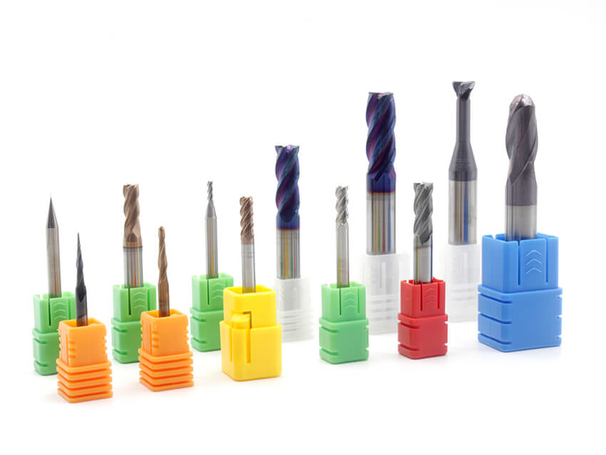
A wall comes off the machine with regular chatter marks. The operator reduces the feed, runs another finishing pass, and still gets an unacceptable surface. On another job, the wall looks clean but the cutter has moved in its holder, leaving the pocket deeper than intended. Both problems deserve a look at tool geometry, although neither proves that the helix angle is wrong.
For solid carbide end mills, helix angle selection is a tradeoff between how the edge enters the cut, where the cutting forces act, and what the complete tool can withstand. Start with the operation and the direction in which the setup is least rigid. Then compare material-specific cutters with suitable flute space, edge preparation and reach.
This guide uses low, medium and high helix ranges to organize that decision. The ranges are practical groupings, not universal standards. Variable helix is a separate design feature that can be used within more than one angle range.
What the helix angle tells you
The helix angle is measured between the tool axis and the tangent to the peripheral cutting edge. A larger angle means the flute wraps around the body more quickly. In otherwise comparable upcut tools, higher helix generally favors smoother shearing and lower radial loading, with greater axial lifting tendency. Lower helix generally reduces lifting but can produce a less smooth cut. These are tendencies, not force calculations.
Helix angle does not specify the core diameter, rake angle, cutting edge radius or carbide grade. A photograph also cannot reliably establish those dimensions. Two tools marked 40 degrees can behave differently because the rest of their geometry differs.
Nor should helix be used as a shortcut for programming chip thickness. Radial chip thinning depends on radial engagement in peripheral milling. A change to a higher helix is not, by itself, a reason to increase feed per tooth.
Helix grouping | Typical selection priority | What to check before ordering |
Low, roughly 15 to 35 degrees | Edge support and reduced lifting in suitable applications | Material approval, actual core geometry and interrupted-cut capability |
Medium, roughly 35 to 45 degrees | A starting point for mixed shop work | Whether the same tool is rated for both slotting and profiling |
High, roughly 45 to 60 degrees | Smooth peripheral cutting and finish-sensitive work | Flute capacity, axial restraint and permitted engagement |
Variable helix | Improved stability where chatter limits the cut | Actual helix design, pitch arrangement and recommended cutting conditions |
The boundaries overlap deliberately. A 45-degree cutter may be marketed as general purpose, high helix or application specific. Use the manufacturer’s application data to resolve the choice.

Low helix tools for demanding entry conditions
For a roughing operation with repeated entry and exit, begin by asking how the edge is failing. Small chips at the cutting edge, a fractured corner and a broken tool body call for different changes. Choosing a lower helix without examining that damage can hide the real problem.
A low-helix design can be a candidate when reduced axial lifting or strong edge support is a priority. The reference range of about 15 to 35 degrees is useful for discussion, but it covers quite different cutters. Do not treat the entire range as a default for steel, cast iron or every difficult alloy.
Consider a steel shoulder interrupted by cross holes. Before testing a different helix, record where the damage begins and check the toolmaker’s recommendation for interrupted cuts. A suitable corner radius, shorter projection or less aggressive re-entry may be more valuable than changing the angle alone. Ask the supplier to identify a complete geometry for that operation.
For full-width slots, check the specified slotting depth and chip clearance. A low angle on the label does not prove that the flute space will accommodate the chips from a deep slot. Likewise, bottom finishing depends on end-edge geometry, runout and machine condition; the peripheral helix does not determine floor quality by itself.
Medium helix tools as a practical starting point
The 35 to 45 degree range is a useful place to start a supplier comparison for general profiling, shoulder milling and mixed roughing and finishing work. It is a broad purchasing category rather than a promise of equal performance in every operation.
For a shop trying to reduce tool inventory, build the standard around a recurring family of jobs. Record the workpiece grades, usual pocket depths and required finish, then choose a cutter series that covers those requirements. Keep a separate tool where a deep slot or tight finishing tolerance makes the compromise expensive.
Imagine a batch of steel brackets with an open shoulder and a closed slot. A cutter that performs well around the outside profile still needs separate slotting parameters. Carrying the profiling feed and depth straight into the slot changes the load and available chip escape space. The nominal helix angle has stayed the same, but the operation has not.
There is also no general rule that radial and axial forces become equal in this range. For process planning, use the actual engagement and tool data. If a test part shows taper or a depth change, measure the tool and setup before deciding that another five degrees of helix will solve it.

High helix tools for peripheral finishing
Higher-helix cutters are often considered for finish-sensitive side milling. The opportunity is especially relevant when a wall can deflect sideways, but the workpiece and toolholder can resist axial loading. Select the cutter around the direction of weakness in the actual part.
For a thin aluminum pocket wall, plan the finishing sequence before selecting a high-helix tool. Specify how much stock remains for the final cut and where the wall retains support. Compare dimensions near the top and bottom of the wall after the test. A glossy surface alone does not establish that the wall is straight or in tolerance.
Long reach needs similar care. Check whether a necked tool can reach the feature without carrying unnecessary flute length. Confirm holder clearance in the CAM model and on the machine. Treat the minimum usable projection as part of the tool specification, so a successful trial can be repeated by the next operator.

Slotting needs an application rating
It is too broad to say that every high-helix end mill is unsuitable for slotting. Some 45-degree aluminum end mills are designed for slotting. Suitability belongs to the complete tool design and its cutting data.
A many-flute finisher should not be assumed suitable for a deep full-width slot merely because another cutter with the same helix works there. Ask for the allowed axial depth, entry method and coolant requirements for the exact part number. If chip packing occurs, examine flute space and chip removal before blaming a longer helical path.
Toolholding is part of the selection
Before a demanding cut, establish tool projection and follow the holder manufacturer’s instructions for shank condition, insertion length and tightening or assembly. A precision collet is not a universal guarantee against pullout. For applications that need additional retention, evaluate a compatible positive anti-pullout system with the toolholder supplier.
After the trial, check projection again. If the tool has moved, treat the result as a retention problem requiring investigation before using the trial to judge cutting geometry.
Variable helix tools when chatter limits the process
Variable helix changes the helical arrangement of the cutting edges. Variable pitch changes their angular spacing around the tool. Manufacturers may combine the features, but the names should not be treated as interchangeable specifications. Both can be used to modify tooth engagement and reduce the tendency for chatter to build.
Regenerative chatter involves the interaction of the current cut with waviness left by earlier tooth passes. Describing every case as a fixed cutting frequency matching a machine resonance is incomplete. Variable geometry can improve the stable cutting range; it does not remove all unstable speeds or compensate for a loose setup.
For a deep pocket that chatters on one wall, document the location and cutting direction. Check whether engagement changes at that point or whether the holder approaches the part. Then compare an application-rated variable-helix cutter with the existing tool. Keep the assembly dimensions documented and use each tool’s recommended starting data.
A medium-helix variable design may be considered for a mixed roughing and semi-finishing workload. A higher-helix version may be considered for finish-sensitive peripheral work. These are candidate categories for trials, not two exhaustive classes of anti-vibration tools.

Match the cutter to the operation
The following matrix is a planning checklist. It does not replace part-number-specific cutting data.
Operation | Candidate to discuss with the supplier | Trial evidence to collect |
Steel shoulder with interrupted entry | Robust edge geometry and suitable low or medium helix | Edge damage location and life over repeated entries |
General steel profiling | Material-rated medium or variable helix | Cycle time, flank wear and dimensional consistency |
Thin aluminum sidewall finishing | Sharp aluminum geometry with suitable medium or high helix | Wall straightness, burrs and surface finish |
Deep full-width slot | Tool explicitly rated for slotting at the required depth | Chip evacuation, spindle load and wear |
Long-reach pocket finishing | Shortest practical assembly with suitable variable geometry | Chatter location, taper and clearance |
Titanium or nickel alloy roughing | Alloy-specific cutter and approved engagement strategy | Wear progression and repeatable tool life |
For titanium and nickel alloys, start with the exact alloy and condition. Avoid purchasing by a broad label such as “difficult materials.” Two quotes are only comparable when they address the same operation, tool dimensions and material state.
Diagnose the symptom before changing the angle
Observed problem | Checks to make first | When a geometry trial is useful |
Repeating sidewall marks | Runout, projection, support and engagement changes | Chatter remains after setup checks |
Step between axial passes | Tool deflection, wear, offsets and stock left for finishing | A controlled comparison can isolate cutting behavior |
Thin wall outside tolerance | Clamping distortion, stock distribution and finishing sequence | The remaining error appears sensitive to cutting load |
Unexpected pocket depth | Tool projection, retention and length compensation | Retention is secure and the depth error is understood |
Chips packed in a slot | Flute capacity, coolant access and slotting parameters | A different slotting geometry offers more suitable clearance |
Use a trial sheet that includes the holder, measured runout, projection, coolant delivery and CAM strategy. Record axial and radial engagement separately. Without that information, the next shift may reproduce the tool number but not the result.
Judge the trial against the part requirement. A quieter cut is useful, but it still needs to meet size, finish and tool-life targets. Include the cost of an extra finishing pass or an early tool change when comparing alternatives. Where possible, repeat the promising condition before approving a production standard.

Build a specification that purchasing can use
An order that asks only for “a 45-degree carbide end mill” leaves too much unresolved. Include diameter, cutting length, reach, flute count and corner form, alongside the workpiece material and operation. State whether variable helix or variable pitch is required, and ask the supplier to confirm the distinction.
For a replacement tool, provide the existing part number and the failure or quality issue being addressed. Ask for a recommended starting condition and a measurable acceptance target. This makes the quote useful to the programmer and gives purchasing a basis for comparing more than unit price.
For your next HNCarbide tooling inquiry, share the workpiece grade, feature drawing, required reach and current machining problem. Use those details to discuss a suitable solid carbide end mill and a controlled trial. The best helix choice is the one that meets the part requirement reliably in your setup.




