 Skip to content
Cutting Resistance in Turning: Causes, Symptoms, and Practical Solutions
Table of Contents
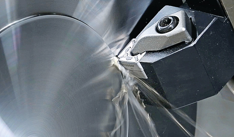
Turning looks simple from outside the machine: the workpiece rotates, the insert feeds into the surface, and chips come off. On the shop floor, the process feels less polite. The insert pushes into the material, and the material pushes back. That reaction is cutting resistance.
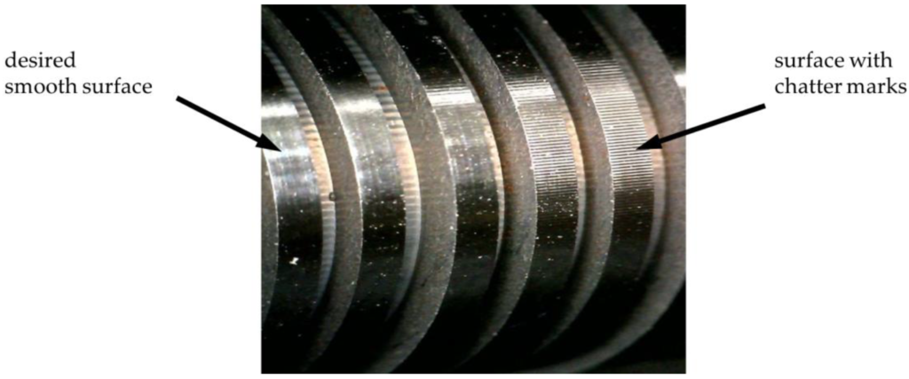
When the resistance stays within the machine’s usable range, the cut sounds steady and the chips leave the cutting zone cleanly. When it climbs too high, several things start to happen at once: spindle load rises, the insert runs hotter, the edge wears faster, and the turned surface may show chatter marks, burrs, tearing, or drifting dimensions. The operator may first notice it as a heavier cutting sound or a load meter that keeps creeping upward.
For production managers and tooling buyers, cutting resistance is not just a physics term. It affects cycle time, insert consumption, machine utilization, and scrap risk. A turning process that overloads the tool may still make parts for a while, but it rarely makes them cheaply.
What cutting resistance means in turning
In turning, the insert must shear material away from the rotating workpiece. The material does not separate freely. It first deforms in front of the cutting edge, then shears into a chip, then slides along the rake face of the insert. Each of these stages consumes force. Workpiece strength, chip thickness, tool geometry, edge condition, friction, heat, and machine rigidity all decide how much force the system must carry.
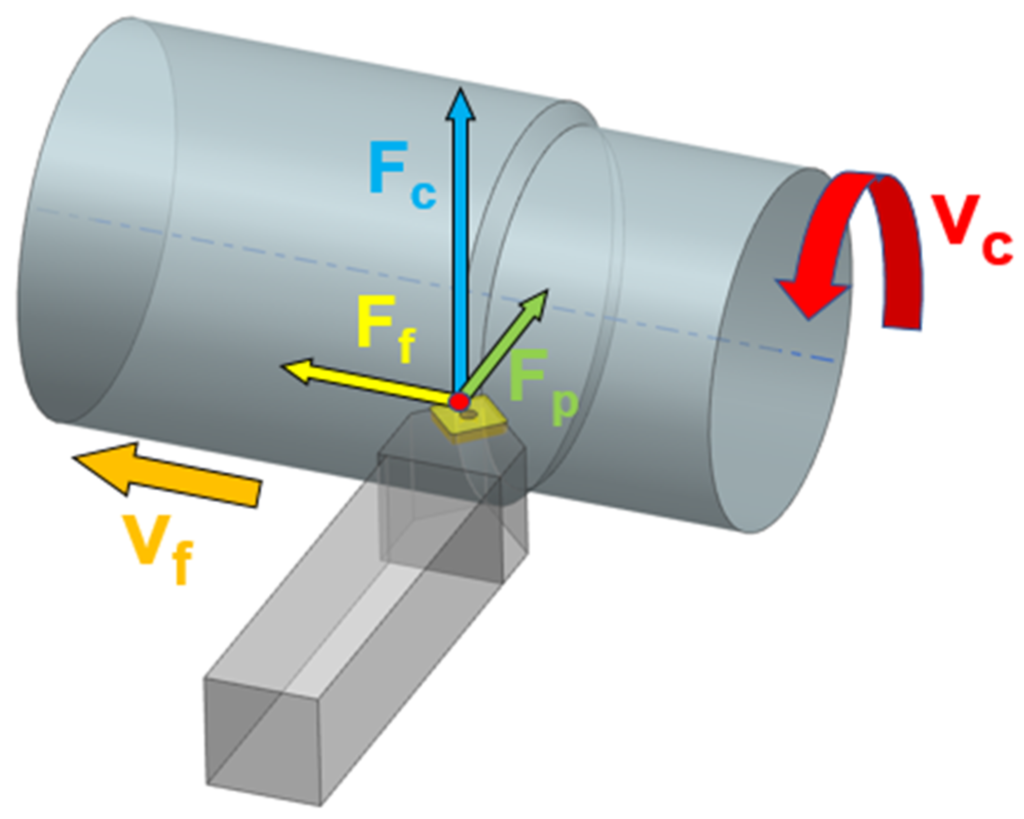
Most turning discussions divide cutting force into three useful components:
Force component | Direction in turning | What it usually affects |
Main cutting force, Fc | Tangential to the rotating workpiece | Spindle load, power demand, heat generation, insert wear |
Feed force, Ff | Along the feed direction | Feed stability, toolholder loading, surface consistency |
Radial or passive force, Fp | Pushes tool and workpiece away from each other | Deflection, chatter, taper, poor dimensional repeatability |
The main cutting force is usually the largest, so it is the one most closely tied to spindle power and load alarms. The radial force often causes the more annoying quality problems. Even if the machine has enough power, a high radial force can push a long shaft away from the tool, deflect a boring bar, or excite vibration in a toolholder with too much overhang.
Common signs that cutting resistance is too high
Excessive cutting resistance usually announces itself before the insert fails. The trick is to read the signs early enough.
The first sign is often machine load. A roughing operation that normally runs at 55 percent spindle load may jump to 75 or 85 percent after a material batch change, insert wear, or coolant problem. If the machine begins to sound strained or the spindle speed drops under load, the process has moved beyond a comfortable cutting window.
Tool temperature is another warning. Blue chips are not automatically bad in every steel turning operation, but sudden color changes can mean the insert is absorbing more heat than before. Built-up edge, crater wear, flank wear, and small edge chipping all increase resistance further, so the problem can feed itself.
Surface quality is the easiest sign for the quality team to see. Chatter marks, tearing, rough rings, burrs at shoulders, or a finish that changes along the length of a shaft often point back to force, rigidity, or chip control. Dimensional drift also belongs in the same discussion. If the part is consistently springing away from the tool, offsets become a temporary patch rather than a real fix.
Chip shape gives useful clues. Long stringy chips can wrap around the workpiece, rub against the surface, and cause secondary cutting. Powdery chips, burned chips, or chips that suddenly stop breaking may point to a mismatch between feed, depth of cut, chipbreaker, material, and coolant delivery.
Shop-floor symptom | Likely force-related reason | First checks to make |
Spindle load rises sharply | Feed or depth of cut is too heavy; workpiece material is harder than expected | Compare actual DOC/feed with program, check material batch and hardness |
Chatter marks appear on the surface | Radial force is exciting a weak setup | Reduce overhang, check clamping, support slender work, inspect insert nose radius |
Insert wears or chips early | Edge is overloaded, too hot, or too weak for the cut | Check grade, edge prep, chipbreaker, coolant, and interrupted-cut conditions |
Burrs or tearing increase | Edge is dull, built-up edge forms, or geometry is too blunt | Inspect the cutting edge under magnification and review cutting speed |
Chips become long or tangled | Chip thickness is outside the chipbreaker’s working range | Adjust feed/DOC, choose a more suitable chipbreaker, improve coolant direction |
Why cutting resistance becomes excessive
Cutting resistance rarely has a single cause. In most real turning jobs, two or three small mismatches stack together until the process becomes unstable.
The cut is too heavy for the system
Feed rate and depth of cut control chip thickness and chip section. If both are increased aggressively, the insert must remove much more material per revolution. This can be acceptable on a rigid CNC lathe with a strong toolholder and a stable workpiece. It becomes risky on a smaller machine, a long overhang, a thin-walled part, or a shaft held far from support.
Roughing operations are where this shows up most clearly. A deep cut may be good for cycle time, but only if the machine, insert, holder, and workholding can carry it without chatter or heat overload.
The insert edge is no longer cutting cleanly
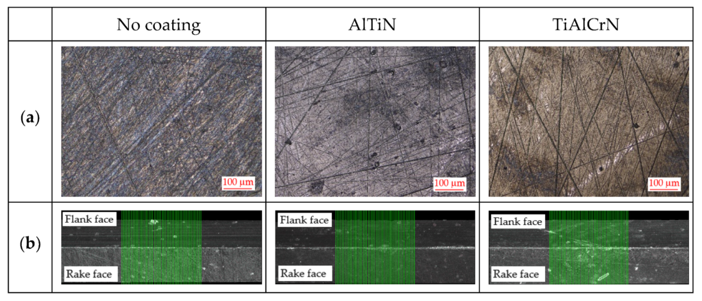
A sharp cutting edge shears material. A worn or chipped edge starts to rub and plough. That change increases cutting resistance, raises heat, and damages the surface. Built-up edge can do the same thing. It changes the effective geometry of the insert, makes the cut inconsistent, and may tear away in pieces that mark the workpiece.
This is why replacing an insert sometimes solves a “machine problem” in five minutes. The machine was not the root cause; it was reacting to a cutting edge that had stopped behaving predictably.
Insert geometry does not match the material or cut
Positive rake inserts and sharp chipbreakers usually reduce cutting force, especially in stainless steel, aluminum, non-ferrous alloys, and finishing cuts. Stronger negative inserts can handle heavier roughing and interrupted cuts, but they often need more power and rigidity.
Nose radius matters too. A larger nose radius can improve finish and strengthen the edge, but it can also increase radial pressure. On a slender shaft or a light-duty setup, that extra radial force may be enough to start chatter.
Chipbreaker and chip evacuation are not working
Chip control is part of force control. If the chip does not curl and break properly, it can rub against the insert, workpiece, or holder. Long chips may wrap around the part and cut the surface again. Packed chips in grooves or shoulders increase friction and heat.
Chipbreakers have working ranges. A finishing chipbreaker may not break chips at a very light feed in gummy material. A roughing chipbreaker may need a minimum chip thickness before it works correctly. If the feed or depth of cut sits outside that range, the tool may be technically “correct” but practically troublesome.
The workpiece material is difficult to cut
Hard steels, work-hardened stainless steels, high-temperature alloys, and tough low-carbon steels can all push resistance upward for different reasons. Hard materials require more force to shear. Tough materials may stretch and smear. Sticky materials increase friction and built-up edge. Materials with inconsistent scale, interrupted surfaces, or hard spots create changing load at the cutting edge.
This is where tooling selection has to be specific. A grade and chipbreaker that work well in free-cutting steel may struggle in 304 stainless or nickel alloy. For B2B buyers, the important question is not “Is this insert good?” but “Is this insert good for this material, this operation, and this machine?”
Rigidity is weak somewhere in the chain
Cutting force travels through the full system: insert, shim, clamp, holder, turret, spindle, chuck, workpiece, and any support device. A weak link turns force into movement.
Common weak points include long tool overhang, small-diameter boring bars, slender shafts without tailstock or steady rest support, worn turret clamping, poor chuck grip, thin-walled parts, and fixtures that were designed for convenience rather than stiffness. Once movement begins, the insert re-enters the cut at a slightly different position. That creates changing chip thickness, which can create more vibration.
Practical ways to reduce cutting resistance
The best response is not always to slow everything down. Reducing cutting resistance means bringing the operation back into balance: parameters, insert geometry, material behavior, coolant, and setup stiffness must fit each other.
Start by reducing the load
If the machine is close to overload, reduce feed or depth of cut first. On a roughing pass, lowering depth of cut often has a direct effect on spindle load. Lowering feed can reduce chip thickness and force, but be careful not to feed so lightly that the insert rubs instead of cuts. For carbide inserts, a tiny feed with a large nose radius can sometimes make finish worse, not better.
For long shafts or weak setups, reducing radial pressure may matter more than reducing power. In that case, try a smaller nose radius, sharper geometry, lighter depth of cut, or better support before accepting a slow, unstable process.
Inspect the insert before changing the program
Before editing feeds and speeds, look at the cutting edge. Check for flank wear, chipping, crater wear, built-up edge, plastic deformation, and thermal cracks. A loupe or microscope can prevent a lot of guessing.
If the insert is worn, changing parameters may hide the problem for a few parts but will not restore edge geometry. Replace the insert, clean the seat, confirm clamping, and then judge the process again.
Choose geometry for the actual cutting condition
For soft or sticky materials, a sharper positive rake geometry can lower force and reduce built-up edge. For hard material, scale, interrupted cuts, or heavy roughing, the edge needs more strength, even if that increases cutting force slightly. Finishing, semi-finishing, roughing, grooving, parting, and boring all need different compromises.
Turning condition | Insert choice that often helps | Watch-out |
Finishing slender shafts | Sharp positive geometry, smaller nose radius | Too light a feed may cause rubbing |
Roughing steel on a rigid CNC lathe | Stronger edge prep, suitable roughing chipbreaker | Do not exceed machine power or holder rigidity |
Stainless steel or gummy alloys | Sharp rake, polished or suitable coated grade, effective coolant | Built-up edge may require speed adjustment |
Interrupted cut | Tough grade, reinforced edge, secure clamping | Very sharp edges may chip early |
Boring with long overhang | Positive geometry, smaller DOC, vibration-damping bar if needed | Boring bars magnify radial-force problems |
Adjust speed with the failure mode in mind
Cutting speed affects heat, built-up edge, coating behavior, and wear pattern. If built-up edge is obvious, a moderate speed increase can sometimes move the cut into a cleaner shearing range. If the insert is burning, deforming, or showing thermal cracking, reducing speed or improving coolant may be the better move.
Speed changes should be made with the insert grade in mind. A coated carbide grade designed for higher temperature can behave differently from a sharp uncoated grade used for aluminum or non-ferrous materials.
Improve chip evacuation and coolant delivery
Coolant is not only for temperature. Properly aimed coolant helps break chips, flush them away from grooves and shoulders, reduce friction, and protect the finished surface from recutting. In turning stainless steel, steel, and many alloy materials, poor coolant direction can make a good insert look bad.
Check whether the coolant actually reaches the cutting zone. A stream that hits the holder but not the chip-tool contact area may look acceptable through the door window while doing little where it matters. For parting, grooving, and deep profiles, chip evacuation deserves special attention.
Increase rigidity before chasing perfect parameters
If chatter is the main symptom, the most useful fix may be mechanical. Shorten tool overhang. Use a larger or stiffer holder. Reduce boring bar projection. Tighten the workholding plan. Support slender shafts with a tailstock, live center, or steady rest. Check whether the insert is seated correctly and whether the turret or tool block is clamping securely.
Parameter changes help, but a weak setup narrows the usable cutting window. A rigid setup gives the process room to run.
A field troubleshooting sequence
When the cut starts to feel heavy, avoid changing five variables at once.
A simple sequence keeps the diagnosis clean:
Step | What to check | What to do if the answer is yes |
1 | Is spindle load or cutting sound suddenly higher than normal? | Reduce feed or depth of cut enough to stabilize the process, then inspect the cause |
2 | Is the insert worn, chipped, or carrying built-up edge? | Replace the insert, clean the seat, and verify clamping before changing the program |
3 | Are chips long, tangled, packed, or rubbing the part? | Adjust feed/DOC into the chipbreaker’s range and improve coolant direction |
4 | Are there chatter marks, taper, or size drift? | Shorten overhang, support the workpiece, review nose radius, and reduce radial pressure |
5 | Did the material batch or hardness change? | Confirm material data and select a grade/geometry for the actual workpiece condition |
This sequence is practical because it starts with what operators can see and hear. It also separates emergency stabilization from root-cause correction. Reducing feed may save the current part, but if the real issue is a dull edge or a flexible setup, the process still needs fixing.
How tooling buyers should think about cutting resistance
For purchasing teams, cutting resistance shows up as cost. Inserts that fail early, machines that run below planned feed, parts that need extra deburring, and operators who keep adjusting offsets all add hidden cost to a turning job.
When comparing carbide turning inserts, ask suppliers for more than a catalog grade name. Provide the workpiece material, hardness, operation type, machine power, holder style, depth of cut, feed, speed, coolant condition, and quality requirement. A good recommendation should connect insert grade, coating, chipbreaker, edge prep, and nose radius to those conditions.
In production, the lowest insert price is not always the lowest cutting cost. An insert that lowers resistance, controls chips, and holds size may reduce cycle interruptions even if the piece price is higher.

Conclusion
Cutting resistance in turning is the material’s reaction against being sheared, deformed, and pushed into chips. When it becomes excessive, the process pays for it through load, heat, wear, vibration, burrs, poor finish, and unstable dimensions.
The fix is usually systematic rather than dramatic. Check parameters, then the cutting edge, then insert geometry, chip control, material behavior, coolant, and rigidity. Each part of the system has to carry its share of the load.
HNCarbide supports turning operations with carbide insert and cutting tool options for different materials, finishing needs, and roughing conditions. For buyers who need stable tool life and cleaner machining results, the best starting point is a clear description of the workpiece, machine, and current failure pattern.





