
Built-Up Edge in Precision Machining: Causes, Tool Selection, and Practical Fixes
Table of Contents
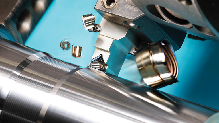
Built-up edge is easy to underestimate because it rarely looks dramatic at first. The spindle sounds normal. The insert or end mill may still look usable. The program has already run good parts before. Then the finish starts to tear, burrs appear on edges that were clean yesterday, and the measured size wanders even though nothing obvious has changed.
For finishing work, that small lump of welded material on the cutting edge can create more scrap than visible flank wear. It changes the effective rake angle, pushes the tool away from the work, breaks off unpredictably, and can drag hard particles across a freshly machined surface. Operators may polish the edge, slow the machine down, change coolant concentration, or swap inserts. Sometimes the problem disappears for a few parts. Then it comes back.
That is the frustrating part. Built-up edge is not a mystery defect. It is a controllable failure mode caused by adhesion, friction, heat balance, and tool-workpiece mismatch. Once a shop treats it as a process problem instead of a random tool problem, the fixes become much clearer.
What built-up edge really is
Built-up edge, often shortened to BUE, forms when part of the workpiece material welds to the rake face or cutting edge during chip formation. It is common in ductile materials because the chip is already being squeezed, heated, and sheared under high pressure. When the interface has enough friction and the temperature sits in the wrong range, the work material sticks to the tool instead of sliding away as a clean chip.
The welded material can become work-hardened and behave like a false cutting edge. For a moment, it may even protect the tool. In finishing, that “protection” is not useful. The deposit changes shape, breaks away, forms again, and leaves a different cutting edge from one revolution or pass to the next.
On the part, this shows up as:
- torn or smeared surface finish
- burrs that repeat at the same feature or exit edge
- orange-peel texture on soft materials
- unstable size even when offsets are correct
- short tool life caused by edge chipping or coating pull-off
The usual high-risk materials include aluminum, copper, low-carbon steel, some alloy steels, stainless steel, and heat-resistant alloys. The exact mechanism changes by material, but the practical pattern is similar: the material has enough ductility and adhesion tendency to weld to the tool under the wrong cutting condition.
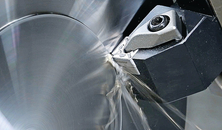
Why it keeps returning after a tool change
Many shops respond to BUE by changing the insert or cutter. That is understandable. The tool is where the deposit is visible. But if the replacement tool has the same edge preparation, coating, chipbreaker, and cutting data, the new tool simply enters the same welding zone.
The process usually looks like this:
Stage | What happens at the cutting edge | What the operator sees |
Rubbing starts | Feed, edge geometry, or depth of cut is too light for clean shearing | Slightly dull finish, more heat than expected |
Adhesion begins | Work material sticks to the rake face or edge | Small burrs, inconsistent chip color or chip flow |
Deposit grows | Layers of material weld and compact under pressure | Size drift, rougher finish, changing cutting sound |
Deposit breaks away | The false edge tears off and may pull coating or tool material with it | Random scratches, microchipping, sudden finish failure |
Cycle repeats | Fresh tool surface is exposed to the same friction condition | Problem returns after a few parts |
If the first countermeasure is only “use a new tool,” the root cause remains. The better question is: why did the chip stop sliding?
Tool selection: start with adhesion control
When built-up edge is the main problem, the tool must be selected for low adhesion and clean shearing before high hardness. A very hard tool with a dull edge and high-friction coating can still weld material badly. In finishing, the best tool often feels almost too sharp compared with a roughing tool.
For carbide tools, fine-grain and ultra-fine-grain substrates are usually preferred for precision work because they can support a sharper, more consistent edge. A coarse substrate or heavy honed edge may survive interrupted roughing, but it increases ploughing in light finishing cuts. That extra rubbing is exactly what BUE needs.
Coating choice should follow the work material. Aluminum and copper usually benefit from polished uncoated carbide, DLC, diamond-like carbon, or diamond coatings when the operation and tool type allow it. The aim is low friction and reduced material pickup. For steels, stainless steels, and heat-resistant alloys, coatings such as AlTiN, TiAlN, TiB2, or other low-adhesion PVD systems may help, but only when paired with the right edge geometry and temperature window.
Plain TiN is not automatically wrong, but it is rarely the first answer for severe adhesion in finishing. It can run acceptably in many general jobs. Where BUE is the reason parts are failing, the coating has to do more than look gold and resist mild wear.
Geometry matters as much as coating
A coating cannot rescue a tool that is rubbing instead of cutting. BUE control normally improves when the cutting edge has a positive rake, sharp land control, a smooth rake face, and enough flute or chipbreaker space to move the chip away.
For aluminum finishing, a polished flute or polished rake face is often more important than coating thickness. The chip has to slide. A rough surface gives soft material places to grab. For stainless steel and superalloys, the edge still needs strength, but an overly blunt hone can create too much contact pressure and heat at the exact point where the material wants to weld.
Use the table below as a practical starting point, not as a catalog rule.
Work material | Tool selection focus | Geometry preference | Common mistake |
Aluminum alloys | Low adhesion, polished surface, sharp carbide | High positive rake, large chip space, polished flute | Using a general steel cutter with a dull edge |
Copper and brass | Sharp edge and controlled burr formation | Positive rake, smooth rake face, stable support | Reducing feed until the tool rubs |
Low-carbon steel | Edge sharpness plus coating that limits welding | Positive or light-honed edge depending on stability | Running in the middle-speed BUE zone |
Stainless steel | Strong edge, heat-resistant coating, chip control | Controlled positive geometry with secure chip evacuation | Taking shallow spring cuts through work-hardened material |
Nickel or heat-resistant alloys | Tough substrate, stable edge, targeted coolant | Strong but not blunt edge, reliable chipbreaker | Losing depth of cut and rubbing the hardened layer |
Cutting speed: avoid the welding window
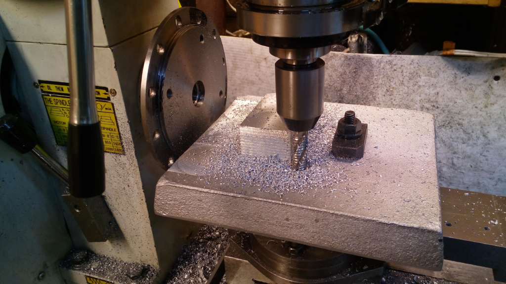
Built-up edge often appears in a middle-speed range where the interface is hot enough for adhesion but not hot or fast enough for the chip to shear away cleanly. In many shop-floor references, the risky band is described roughly around 20 to 80 m/min, though the exact window depends on material, tool, coating, coolant, and operation.
The important point is not the exact number. The point is to stop hovering in the condition where material can repeatedly weld and break away.
Two strategies can work:
Low-speed stable cutting keeps temperature and adhesion under control. This is common for difficult stainless steels, some heat-resistant alloys, or rigid setups where conservative cutting is needed. The cut still needs enough feed and depth to shear material. Slow rubbing is worse than slow cutting.
High-speed finishing moves heat into the chip and reduces the time available for adhesion. This is common in aluminum and other non-ferrous finishing, especially with sharp polished tools. High speed only works when chip evacuation and balance are good. If chips recut or the flute packs up, the advantage disappears quickly.
What usually fails is the in-between compromise: moderate speed, tiny feed, small skim cut, weak lubrication. It feels safe. It often makes BUE worse.
Feed and depth of cut: do not polish the problem into the part
When finish goes bad, many operators reduce feed. Sometimes that helps, especially if the surface roughness target is tight and the original feed was aggressive. With BUE, however, feed reduction can cross the line from cutting into rubbing.
Every tool needs a minimum effective chip load. Below that, the edge slides over the work surface, generates heat, work-hardens the material, and gives the chip less reason to separate cleanly. This is why a finishing pass with a tiny radial or axial engagement can produce more trouble than a heavier semi-finish pass.
Depth of cut deserves the same attention. If the finishing allowance is too small, the tool may ride over scale, a work-hardened skin, or the marks left by roughing. In stainless steel and high-temperature alloys, repeated light passes can make the next pass worse. A stable finishing strategy leaves enough material for a real chip, then removes it with a tool suited for that load.
Lubrication first, cooling second
Built-up edge is often described as a heat problem, and heat is involved. In practice, it is more useful to think of it as an adhesion and friction problem. Flood coolant can lower bulk temperature, but if it never reaches the tool-chip interface, the material may still weld to the edge.
For aluminum and copper, lubrication is often the deciding factor. Dry cutting may work in some high-speed aluminum operations with the right tool and evacuation, but if BUE is already active, a targeted lubricant, mist, or MQL-style approach can be more effective than simply increasing coolant volume. The fluid needs to wet the contact area and help the chip slide.
For steels and stainless steels, well-aimed flood coolant can help remove heat and flush chips, especially in slots, grooves, and internal features. In difficult materials, coolant strategy must also avoid thermal shock if the tool is designed for hot cutting. The right answer depends on the operation, but one rule holds: coolant that misses the cutting edge does not solve BUE.
Material-specific fixes
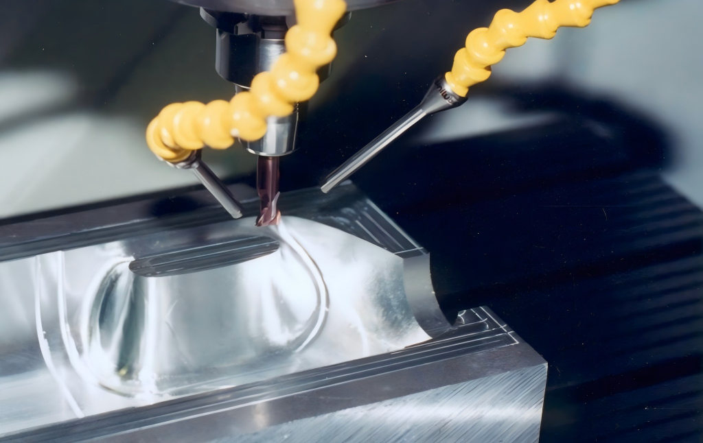
Aluminum and copper usually need the cleanest shearing action. Use sharp positive geometry, polished flutes or rake faces, low-adhesion coatings where suitable, and enough feed to form a chip. If the machine has the spindle speed and rigidity, move decisively into high-speed finishing rather than creeping through the middle range. Keep chips moving. Packed chips can weld again even when the tool itself is correct.
Low-carbon steel and many alloy steels need a balance between edge sharpness and heat control. If the speed sits in the BUE range, test a lower controlled speed or a higher finishing speed instead of making small percentage changes. Avoid very light finishing passes that rub. If the insert coating is peeling with material stuck to it, the coating and edge preparation are probably mismatched to the job.
Stainless steel and heat-resistant alloys punish hesitation. Maintain a feed and depth of cut that cut below the work-hardened layer. Use a tool with enough edge strength, but do not turn the edge into a plough. Coolant should support chip evacuation and temperature control. If the surface starts tearing after a few passes, check whether the process is creating a hardened skin and then rubbing through it on the next pass.
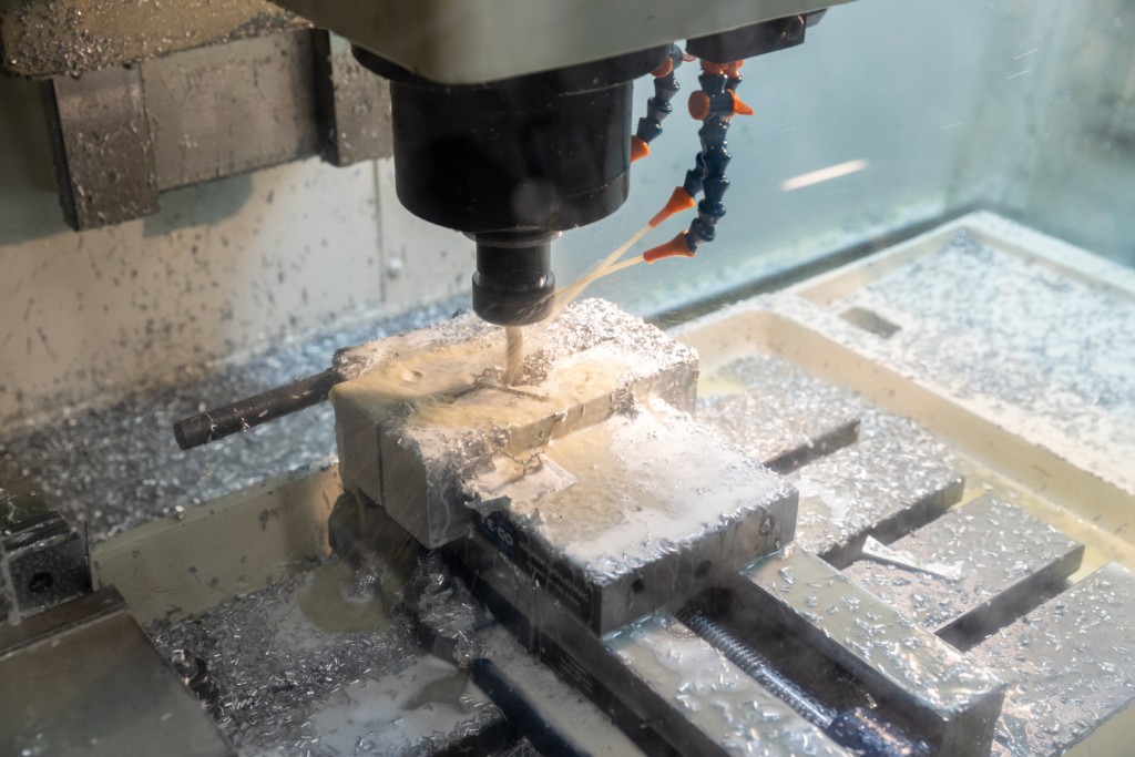
A shop-floor troubleshooting checklist
When BUE keeps returning, do not change five variables at once. Confirm the deposit, then work through the process in a sequence.
Checkpoint | What to inspect | Corrective action |
Cutting speed | Is the process sitting in a repeatable adhesion window? | Test a clear low-speed or high-speed strategy instead of minor speed tweaks |
Feed per tooth or feed per rev | Is the edge making a chip or only rubbing? | Restore minimum effective chip load for the tool and material |
Finishing allowance | Is the pass too shallow to cut below the damaged layer? | Leave enough stock for a clean finishing chip |
Tool geometry | Is the edge too blunt, negative, or rough for the material? | Use sharper positive geometry and smoother chip contact surfaces |
Coating | Does material stick to or tear the coating? | Select a low-adhesion coating or polished uncoated carbide where appropriate |
Chip evacuation | Are chips trapped, recut, or packed in the flute? | Increase chip space, improve air/coolant direction, or change tool style |
Lubrication | Does fluid reach the tool-chip interface? | Aim coolant correctly or use targeted lubricant/MQL for sticky materials |
What buyers should ask tool suppliers
For production buyers, BUE reaches beyond the machine. It affects tool consumption, inspection time, deburring labor, and customer complaints about finish. When sourcing carbide end mills, drills, or inserts for sticky materials, ask for more than grade and coating names.
A useful supplier conversation should cover the work material, hardness, operation type, finishing allowance, coolant method, expected surface finish, and machine limits. Ask whether the tool uses polished flutes, a specific edge preparation, or a coating intended for adhesion control. For aluminum, ask directly about chip welding and built-up edge. For stainless and superalloys, ask how the tool handles work hardening and whether the recommended cutting data preserves chip load.
The lowest unit price is not always the lowest cost per part. A tool that prevents two extra deburring steps or one quality hold can pay for itself quickly.

Conclusion
Built-up edge is one of the most stubborn finishing problems because it hides behind normal-looking cutting conditions. The real fix is rarely one magic coolant or one emergency tool change. It comes from matching the tool to the material, keeping the edge sharp enough to shear, moving out of the adhesion speed window, maintaining real chip load, and getting lubrication to the contact zone.
For shops cutting aluminum, copper, stainless steel, alloy steel, or heat-resistant materials, HNCarbide can help review tool geometry, carbide grade, coating options, and finishing parameters for applications where burrs and torn surfaces keep coming back. A small change at the cutting edge can save a lot of time at inspection and deburring.




