
11 End Mill Wear Patterns and What They Reveal About Your Milling Process
Table of Contents
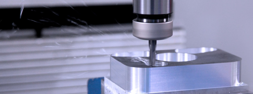
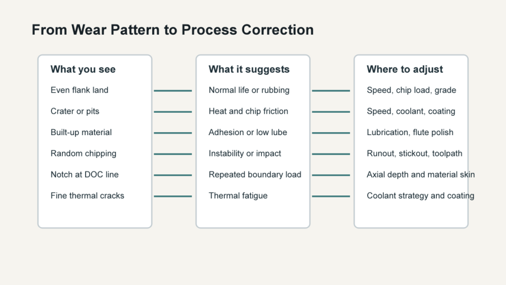
Every worn end mill is a process record. The cutting edge shows where the heat went, whether chips left the cut cleanly, how rigid the setup really was, and whether the tool geometry matched the workpiece material.
For a CNC shop, this matters because tool wear is rarely just a tooling cost. A cutter that wears predictably can be built into a stable tool-life plan. A cutter that chips, loads up, or breaks without warning can scrap parts, damage holders, and make operators lose trust in the program.
This guide breaks down 11 common wear patterns seen on solid carbide end mills. The goal is not to turn every machinist into a lab inspector. It is to help production teams look at the worn tool, ask better questions, and make the next adjustment with a reason behind it.
Quick Reference: Wear Pattern, Process Signal, and First Check
Wear pattern | What it usually tells you | First area to check |
Uniform flank wear | Normal tool-life progression when it develops gradually | Speed, feed, coolant, tool grade |
Crater wear, including pitting | Excessive heat and chip friction on the rake face | Cutting speed, coating, coolant delivery |
Micro-chipping, including point chipping | Edge instability, vibration, impact, or excessive load | Tool runout, stickout, rigidity |
Built-up edge | Work material welding to the cutting edge | Speed, lubrication, flute polish, coating |
Notch wear | Local rubbing or hardening at the depth-of-cut line | Axial depth, work hardening, edge prep |
Chip evacuation wear | Recut chips damaging the edge and flute | Chip space, coolant/air blast, flute count |
Step wear on rake face | Heat and friction concentrated near the cutting edge | Feed/speed balance and tool geometry |
Flaking | Coating or surface layer breaking away | Thermal shock, adhesion, coating choice |
Comb cracks | Thermal fatigue from interrupted heating and cooling | Coolant strategy and cutting speed |
Non-uniform micro-chipping | Random stress points from vibration, hard spots, or chip recutting | Holding, material condition, toolpath stability |
Catastrophic breakage | Overload or ignored warning wear | Program load, runout, holder, chip evacuation |
1. Uniform Flank Wear
Uniform flank wear is the wear pattern you usually want to see at the end of a stable tool life. It appears as a relatively even wear land along the clearance face behind the cutting edge. In a good process, it grows gradually and predictably.
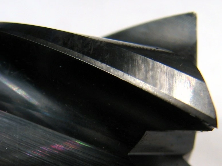
The problem is not flank wear itself. The problem is flank wear that develops too fast, becomes wide early in the run, or starts affecting part size and surface finish before the expected tool change point. In steel, cast iron, stainless steel, titanium, and nickel alloys, the wear rate will differ, but the basic message is similar: the edge is rubbing and losing material under load.
Common drivers include excessive cutting speed, insufficient coolant concentration or delivery, an end mill grade that lacks abrasion resistance for the workpiece, or a feed per tooth that is too light and causes rubbing instead of cutting. Very small chip loads can look gentle on paper, but they often make the edge polish the material rather than shear it.
To troubleshoot, confirm the tool is suitable for the material, then check whether the programmed chip load is high enough for the edge radius. If the cut is stable but wear is simply too fast, reduce surface speed, improve coolant concentration, or move to a coating/substrate better matched to abrasive wear.
2. Crater Wear on the Rake Face
Crater wear forms on the rake face, where the chip slides across the tool. It is less common in many milling jobs than flank wear, but when it appears clearly, it points toward heat, chip friction, and sometimes diffusion-related wear at the tool-chip interface.
In practical terms, crater wear weakens the cutting edge from behind. The tool may still look acceptable from the side, but the edge support is being eaten away. That raises the risk of chipping or sudden fracture as the crater deepens.
The first checks are cutting speed, coolant access to the cutting zone, coating selection, and rake geometry. A tool that works well in low-carbon steel may not survive the same thermal load in stainless, titanium, or nickel alloys. If crater wear appears early, reduce cutting speed before reducing feed too aggressively. A very low feed can increase rubbing time and still leave the tool hot.
Pitting: a localized form of rake-face wear
Pitting is a more localized form of rake-face damage. Instead of a smooth crater, small eroded spots appear where heat, abrasion, and chemical interaction have attacked the tool surface. It often shows up when the work material has strong adhesion or chemical affinity with the tool at cutting temperature.
Pitting is easy to underestimate because it may begin as tiny marks. The risk is that these pits become stress concentrators. Once they grow, the edge can lose support and start to chip.
Start by confirming the tool grade and coating are intended for the material. Then look at heat control: coolant concentration, delivery direction, air blast, MQL, or a dry strategy if the coating and material support it. Lower cutting speed and feed if the process is clearly overheated, but avoid creating a rubbing condition with an unrealistically light chip load.
3. Micro-Chipping
Micro-chipping is a small fracture of the cutting edge. Under magnification it looks like tiny missing pieces along the edge, but on the machine it may show up as a sudden change in sound, small burrs, unstable finish, or a faster rise in spindle load.
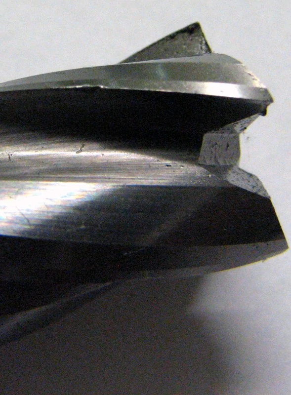
This failure is often linked to stability. Long stickout, poor holder condition, excessive runout, weak workholding, aggressive radial engagement, and interrupted entry can all overload a brittle carbide edge. Chipping can also happen when the selected tool has the wrong edge prep or coating for the material.
Keep the tool as short as the job allows. Check runout at the tool, not only at the holder. Review feed per tooth, radial width of cut, and entry strategy. If chips are packing in the flute, fix evacuation before blaming the carbide. Recut chips can strike the edge repeatedly and make a good tool look defective.
Point chipping: when the damage stays in one spot
Point chipping is localized chipping at a specific spot on the cutting edge. It is closely related to micro-chipping, but the location tells a stronger story. The damage may occur at the corner radius, near the depth-of-cut line, or at one flute more than the others.
If one flute is worse, check runout, tool balance, holder wear, and clamping consistency. If the chipping appears during cornering, review engagement. A sharp internal corner can briefly push the cutter into a much heavier cut than the straight-line toolpath suggests.
Trochoidal milling, adaptive clearing, corner feed reduction, and smoother lead-in/lead-out moves can help. If chatter is present, do not chase the issue only with speed changes. Look at the full system: machine, holder, tool projection, fixture, toolpath, and material condition.
4. Built-Up Edge
Built-up edge occurs when workpiece material welds or smears onto the cutting edge and rake face. It is common in sticky materials such as aluminum, low-carbon steel, some stainless steels, and titanium alloys when heat, pressure, and lubrication are not well controlled.
The danger is that built-up material changes the cutting geometry. The tool may stop cutting cleanly, push material, tear the surface, or break away chunks of adhered material that take carbide with them. Parts may show poor finish, burrs, dimensional drift, or inconsistent edge quality.
Increasing cutting speed can sometimes reduce built-up edge by moving out of the low-temperature adhesion zone, especially in aluminum. Better lubrication, polished flutes, sharper geometry, and coatings designed for low adhesion also help. For aluminum, avoid coatings or edge preparations that encourage welding. For stainless and titanium, balance lubrication and chip evacuation carefully, because heat and adhesion often arrive together.
5. Notch Wear
Notch wear is a groove or localized wear mark at a specific position on the cutting edge, often around the depth-of-cut line. It is frequently caused by rubbing, work-hardened material, abrasive scale, interrupted contact, or repeated contact at the same axial boundary.
In stainless steel and nickel alloys, the workpiece surface can harden under previous passes. If the end mill keeps re-entering the same hardened line, a notch can form. Once the notch grows, it becomes a weak point that may lead to chipping or breakage.
If the part geometry allows it, vary the axial depth of cut so the same point on the tool is not always carrying the boundary load. Check whether the material has scale, flame-cut skin, or hard spots. Reduce cutting speed if heat and abrasion are high, and use a tool geometry intended for the material instead of a general-purpose cutter pushed beyond its comfort zone.
6. Chip Evacuation Wear
Chip evacuation wear can look similar to notch wear or edge chipping, but the cause is different. Here, chips are not leaving the cutting zone cleanly. They pack in the flute, recut against the edge, or get trapped between the tool and workpiece.
This is common when slotting too deep with too many flutes, machining gummy material with poor chip space, using weak coolant direction, or running a toolpath that creates heavy chip volume in a narrow pocket. In deep slots, chip evacuation can become the limiting factor long before carbide strength becomes the limiting factor.
Reduce axial or radial depth of cut if chips cannot clear. Use fewer flutes, a higher helix, chipbreaker geometry, air blast, through-coolant, or a tool designed for the material. In aluminum, flute polish and chip space are often more important than raw coating hardness. In steels, controlled chip formation and coolant access may matter more.
7. Step Wear on the Rake Face
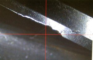
Step wear appears on the rake face near the intersection of the rake and flank surfaces. It often looks like a small ledge, groove, or stepped surface close to the cutting edge. The usual causes are concentrated friction and heat in the cutting zone, especially when the tool stays in steady contact under a demanding load.
This wear mode matters because it changes how chips flow across the rake face. Poor chip flow raises cutting forces, heat, and the risk of later chipping. The process may continue for a while, but the margin is getting smaller.
Improve coolant or lubrication first if the process allows it. Then review feed and speed together. Reducing only one parameter may not solve the problem if the chip still rubs. Tool flute form, rake angle, coating, and edge prep should match the workpiece material and the operation, whether roughing, finishing, slotting, or high-efficiency milling.
8. Flaking
Flaking is the loss of small surface fragments from the tool. On coated carbide end mills, it may appear as coating delamination or patches where the coating has separated from the substrate. It is often tied to thermal stress, mechanical impact, adhesion, or cutting parameters that overload the coating system.
Flaking is not just cosmetic. Once the coating opens, the exposed area can wear faster, attract built-up edge, or become the starting point for edge failure. In hard materials, thermal cycling and interrupted cuts can make this worse.
The response is to stabilize the process. Reduce chatter, avoid severe thermal shock, confirm the coating is suitable for the material, and keep lubrication consistent. If flaking appears together with built-up edge, focus on adhesion control. If it appears with cracks or chipping, focus on impact and heat cycling.
9. Comb Cracks
Comb cracks are a series of fine crack lines, often roughly perpendicular to the cutting edge or arranged like teeth. In milling, the interrupted cut repeatedly heats and cools the edge. That thermal cycling can create fatigue cracks, especially at high cutting speeds or with inconsistent coolant application.
Flood coolant can help in many operations, but in some high-temperature interrupted cuts, poor coolant delivery may shock the edge instead of cooling it evenly. Dry machining with a suitable coating, MQL, or more controlled coolant delivery may perform better in certain materials. The right choice depends on the material, coating, machine enclosure, chip control, and surface integrity requirements.
Reduce excessive cutting speed, avoid unstable engagement, and choose a substrate/coating combination with better thermal shock resistance. Do not ignore comb cracks. They often appear before more serious edge failure.
10. Non-Uniform Micro-Chipping
Non-uniform micro-chipping appears randomly along the edge rather than evenly. It usually starts from small cracks caused by mechanical or thermal stress. Common triggers include intermittent cutting, chatter, weak clamping, hard spots in the workpiece, chip recutting, or inconsistent stock allowance.
This is one of the harder patterns to troubleshoot because several causes can look similar. A useful approach is to separate the checks into three groups: machine/setup, cutting condition, and material. If the tool is held rigidly and runout is low, look at engagement and chip evacuation. If the toolpath is stable, inspect the material for hard inclusions, heat-affected zones, scale, or interrupted surfaces.
Regular tool inspection helps here. Catching small random chips early gives the team a chance to adjust before the tool moves into full fracture.
11. Catastrophic Breakage
Catastrophic breakage is the failure mode no shop wants to normalize. The tool snaps, loses a major section, or breaks at the flute, shank, or corner. It can damage the part, fixture, holder, spindle, or machine enclosure. At high speed, it can also create a safety risk.
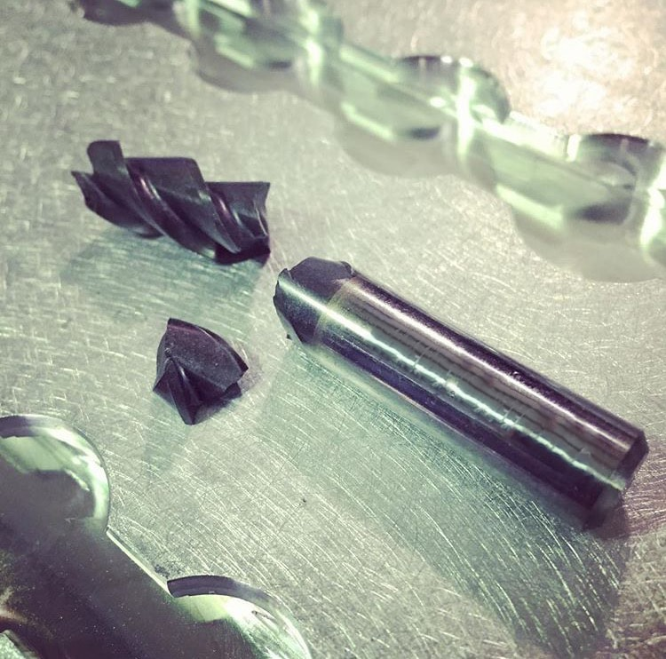
Breakage can happen from a single overload, but it often follows warning signs that were already visible: severe chipping, chip packing, notch wear, excessive runout, chatter, or a tool run beyond its stable life. A broken end mill should trigger a process review, not only a tool replacement.
Check the holder, collet, hydraulic chuck, shrink-fit condition, and runout. Keep stickout short. Confirm the correct tool diameter, flute count, helix angle, coating, and substrate for the job. Review entry moves, ramp angle, corner engagement, axial and radial depth of cut, and chip evacuation. If a tool breaks repeatedly in the same feature, the feature is telling you something.
Material-Specific Clues
Workpiece material | Wear patterns to watch | Practical focus |
Aluminum alloys | Built-up edge, chip packing, poor finish from adhesion | Sharp geometry, polished flutes, chip space, high-speed strategy, effective air/coolant |
Carbon and alloy steels | Flank wear, chipping, notch wear in interrupted cuts | Balanced chip load, stable holding, coating matched to hardness |
Stainless steels | Built-up edge, notch wear, work-hardening-related chipping | Positive geometry, controlled heat, avoid rubbing, consistent feed |
Titanium alloys | Adhesion, chipping, crater wear, thermal cracks | Heat control, sharp edge, stable engagement, suitable coating and coolant strategy |
Nickel-based alloys | Notch wear, crater wear, flaking, catastrophic edge failure | Conservative speed, rigid setup, strong edge support, coolant and tool-life discipline |
Cast iron | Abrasive flank wear, edge rounding | Wear-resistant grade/coating, dust/chip control, avoid unnecessary rubbing |
A Shop-Floor Inspection Routine That Actually Helps
The best time to learn from wear is before the tool has completely failed. Pull tools at a planned interval during process development, clean the edge, and inspect the same locations each time. A phone camera with a macro lens can help, but a basic toolmaker’s microscope or digital inspection scope is better for repeatable records.
Record the tool number, material, operation, holder, stickout, speed, feed per tooth, axial depth, radial width, coolant method, cutting time, and observed wear. This does not need to become a paperwork burden. Even a simple photo log can show whether a change improved the failure mode or only moved it somewhere else.
For production parts, define a tool-life limit based on part quality as well as visible wear. A cutter may still run, but if it is producing burrs, poor surface finish, tapered walls, or unstable dimensions, it has already reached the practical end of life for that operation.
Troubleshooting Actions by Adjustment Type
Adjustment area | Helps most with | Watch-outs |
Reduce cutting speed | Fast flank wear, crater wear, pitting, thermal cracking | Do not create rubbing by pairing low speed with too-light chip load |
Increase feed per tooth within limits | Rubbing-related flank wear and built-up edge | Check horsepower, rigidity, surface finish, and tool deflection |
Improve coolant concentration or delivery | Heat wear, built-up edge, chip evacuation problems | Poorly aimed coolant may not reach the active edge |
Shorten tool stickout | Chipping, chatter, breakage | Confirm reach still clears fixture and part geometry |
Change flute count or helix | Chip packing, vibration, material mismatch | More flutes do not always mean higher productivity in slots |
Use adaptive/trochoidal toolpaths | Point chipping, corner overload, breakage | Requires correct engagement limits and machine dynamics |
Change coating/substrate | Abrasion, heat, adhesion, flaking | Match coating to material, coolant strategy, and cutting temperature |
Improve holder and runout control | One-flute chipping, poor finish, breakage | Measure runout at the cutting edge whenever possible |
What Buyers Should Ask When Wear Keeps Repeating
When an end mill fails early, the purchase order rarely contains enough information to solve the problem. Tooling buyers and engineers should share the material grade and hardness, operation type, slot or side milling condition, reach requirement, holder type, machine taper, coolant method, and current speed/feed data with the supplier.
For repeat problems, send photos of the worn edge. A supplier can make a much better recommendation from a clear wear image than from the sentence “tool life is short.” The correct answer may be a different coating, a tougher substrate, a sharper edge, a variable helix design, a chipbreaker, or simply a process adjustment.

Conclusion
End mill wear is not random noise. Uniform flank wear usually means the process is under control. Crater wear points to heat and chip friction. Built-up edge points to adhesion. Chipping points to instability, impact, or edge overload. Notch wear points to a repeated stress line. Catastrophic breakage means the process has passed its warning zone.
For HNCarbide customers, the most useful conversation often starts with the worn tool itself. Share the material, operation, holder, coolant method, and wear photos, and the tool selection becomes much more precise than choosing from diameter and flute count alone.




