
What “Tool Location Point” and “Tool Change Point” Really Mean in CNC Machining
Table of Contents
Why these two concepts prevent most headaches
Two ideas quietly protect parts, tools, fixtures, and schedules every day: the tool location point (TLP) and the tool change point (TCP). The TLP is the geometric reference point on a tool that the control “believes” and uses for positioning and compensation. The TCP is a safe, repeatable machine position chosen specifically for tool swaps. Mastering these—together with a sensible touch-off strategy—turns zero-setting from a mysterious ritual into a reproducible, auditable process.
In many shops, the touch-off point is chosen to be exactly the program origin. That keeps programming straightforward, probing simple, and inspection consistent. When the TLP is accurately related to that point through offsets, every tool lands where the model says—no drama, no guessing.
Glossary: the minimum vocabulary to get everyone aligned
Touch-off point: The physical spot on the part or fixture you use to establish the work coordinate system. It’s where you probe, edge-find, or carefully “kiss” with a tool to set zero.
Program origin (work zero): The X/Y/Z = 0,0,0 that your CAM or hand programming references. It often equals the touch-off point, by design.
Tool location point (TLP): The geometric point on the tool that the CNC uses as the reference. For a flat end mill it’s the center of the bottom face; for a ball end mill it’s either the ball apex or the ball center (be consistent); for a drill it’s the drill point. On lathes it’s the tool tip or the nose-radius center when compensation is used.
Tool change point (TCP): A safe, clear machine position for swapping tools—automatic on machining centers and most lathes, or manual on simpler machines. It must be outside the part and fixture envelope with generous Z clearance.
Offsets: Numbers in the control that tie machine coordinates to your part and tools (work offsets for the part; tool length and diameter or nose-radius for the tools).
Choosing the touch-off point: practical principles
The drawing might specify: “Use the intersection of the locating pin’s centerline and plane A as the touch-off.” That is an excellent choice because:
Programming is simpler. You dimension directly from a functional datum, avoiding conversion steps.
Probing is easy. The feature is accessible and well-defined.
Inspection is consistent. The CMM and the machine “speak the same origin.”
If the touch-off can’t be on the part (visibility, access, or collision risk), select a fixture feature rigidly linked to the part’s datum and record the exact relationship. The key is traceability: anyone should be able to read the traveler and reproduce the zero without inventing new steps.
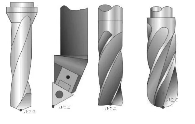
What exactly is the tool location point (TLP)?
Milling tools
Flat end mills or cylindrical cutters: TLP is the intersection of the spindle centerline with the tool’s bottom face.
Ball end mills: Decide up front whether the TLP is the apex or the ball center. Many CAM posts assume the apex in Z and the cutter center in X/Y, but not all do—lock your convention and stick to it.
Drills: TLP is the drill point.
Lathe tools
With nose-radius compensation, the control effectively references the center of the nose radius and calculates the actual contact point from the programmed path, the radius value, and the orientation. Without compensation, the TLP is the physical tip and you must program the tip path explicitly.
Why it matters
The TLP is the point your offsets “aim” at the touch-off point. If your CAM assumes ball-apex and the control’s length measurement references ball-center, your Z will be wrong by the nose
Offsets: turning the concept into motion
Work offsets (e.g., common G54-type systems): Define the transform from machine coordinates to part coordinates. They anchor your program origin in space.
Tool length offsets: Store the distance from the machine’s reference plane (gauge line, table probe, etc.) to each tool’s TLP along Z.
Cutter radius compensation or declared tool diameter: Either you program cutter-center paths and let the control offset laterally by the tool radius, or you program part-geometry paths and maintain the diameter in CAM. Both methods work—choose one and be consistent.
Lathe geometry/wear offsets and nose-radius values: Geometry offsets set the base position of the TLP; wear offsets make small production corrections; nose-radius and orientation allow correct compensated profiles.
The mental model: offsets “bring” the TLP to the touch-off point of your chosen work zero, without you ever typing raw machine coordinates during cutting.
The tool change point (TCP): where, why, and how to pick it
The TCP exists to avoid collisions during tool swaps and to give every program a predictable “safe island.” Good TCPs share three traits:
Clearance: Above clamps, fixtures, and the tallest part feature, and far enough in X/Y (or X/Z on lathes) to avoid side hits by long tools.
Consistency: The same location works across most tools and jobs, so operators internalize it.
Transparency: Programmers and operators know exactly which machine-coordinate position it is, and it is documented in the setup sheet.
On vertical machining centers, a reliable strategy is to retract to a high machine Z and move to a clear X/Y corner of the table before a swap. On horizontals, place the TCP above pallet centerline but outside the tombstone—long tools then clear during index. On lathes, index at a position with large X (clear of the chuck) and positive Z (clear of stock), away from tailstock or steady rest.
Thin-wall parts: clamping force and deformation
Your source emphasized the link between where you apply clamping force and how thin-walled parts deform:
Clamping a thin sleeve on a narrow ring or away from structural support induces elliptical distortion. The part returns elastically once unclamped, making the final size and roundness wander.
Two robust improvements:
(a) Use soft jaws or expanding mandrels shaped to the part, positioning the force path through stiffer sections.
(b) Add sacrificial rings or split rings to spread the load during machining, then remove them later.
This matters for zero-setting because if the part moves when clamped, the touch-off point moves with it. Establish the clamping method first, then set zeros; if you must change clamping mid-process, re-verify the datum.
Compact, repeatable workflows
Machining center (probing or edge-finding)
Load a short reference tool or probe.
Select the work offset you intend to use for the first part.
Touch off Z on the chosen reference plane and write it into the work offset.
Touch off X/Y at the datum (for example, the intersection of the locating pin centerline and plane A) and write those values to the same work offset.
Measure and store tool length offsets for every tool relative to the same reference.
If you rely on cutter-radius compensation, store the actual tool diameters and confirm lead-in/lead-out moves in CAM.
CNC lathe (tool setter or manual)
Home the machine; index the first tool.
Touch the face and the OD (or use the tool setter) to set geometry offsets in X and Z.
Enter nose-radius value and orientation for that tool.
Face the part and call that surface Z zero; spindle centerline is X zero by definition.
Use wear offsets to dial in finish size during production.
These steps are boring by design—that’s a feature. When followed, first-article approvals arrive sooner and repeat jobs restart without detective work.
Three short tables you can pin next to the machine
Key Terms at a Glance
Term | What it means in practice |
Touch-off point | Physical point used to establish the work zero on the part or fixture |
Program origin | The X/Y/Z = 0,0,0 used in programming (often equals the touch-off point) |
Tool location point (TLP) | Geometric point on the tool used as the reference (flat bottom center, ball apex/center, drill point, lathe tip or nose-radius center) |
Tool length offset | Z distance from machine reference to the tool’s TLP |
Cutter radius/diameter data | Lateral compensation information for milling tools |
Tool change point (TCP) | Safe machine position for tool swaps, outside the part envelope |
Choosing a Safe TCP by Machine Type
Machine | Safe TCP strategy | Pitfalls to avoid |
Vertical machining center | High machine Z, clear X/Y away from fixtures | Changing tools over the part or clamps |
Horizontal machining center | Above pallet centerline, outside tombstone | Indexing with long tools too close to the work |
CNC lathe | Large X (clear chuck), positive Z (clear stock) | Tailstock/steady-rest interference; long boring bars |
Manual-change CNC mill | Define a fixed “tool-change square” on the table | Forgetting to return to the correct work offset afterward |
Tool-Setting Methods (Pros & Cons)
Method | Accuracy | Speed | Pros | Cons |
Spindle probe | High | Medium | Automatic, consistent, writes offsets | Cost; needs calibration |
Table tool setter | High | High | Fast, repeatable H offsets | Requires clean routine and discipline |
Edge-finder / paper | Medium | Medium-low | Cheap, universal | Operator-skill dependent |
Lathe tool setter arm | High | High | One-touch geometry offsets | Clearance and setup attention required |
Common pitfalls and quick fixes
Drift or “walking” at the start: TLP definition for a ball end mill inconsistent between CAM and the control; align conventions and re-measure length.
Unexpected thickness or step at Z surfaces: Z reference plane for the work offset was different between operations; standardize the Z datum and document it
Clamp collisions during tool changes: TCP was inside the part envelope or at insufficient Z; redefine TCP with the tallest tool in mind.
Lathe shoulders not to size or with scallops: Nose-radius value or orientation incorrect; verify both before cutting and ensure compensation is active when needed.
Thin-wall roundness out of control: Clamping path too far from stiff regions; switch to shaped soft jaws or an expanding mandrel and re-zero after clamping.
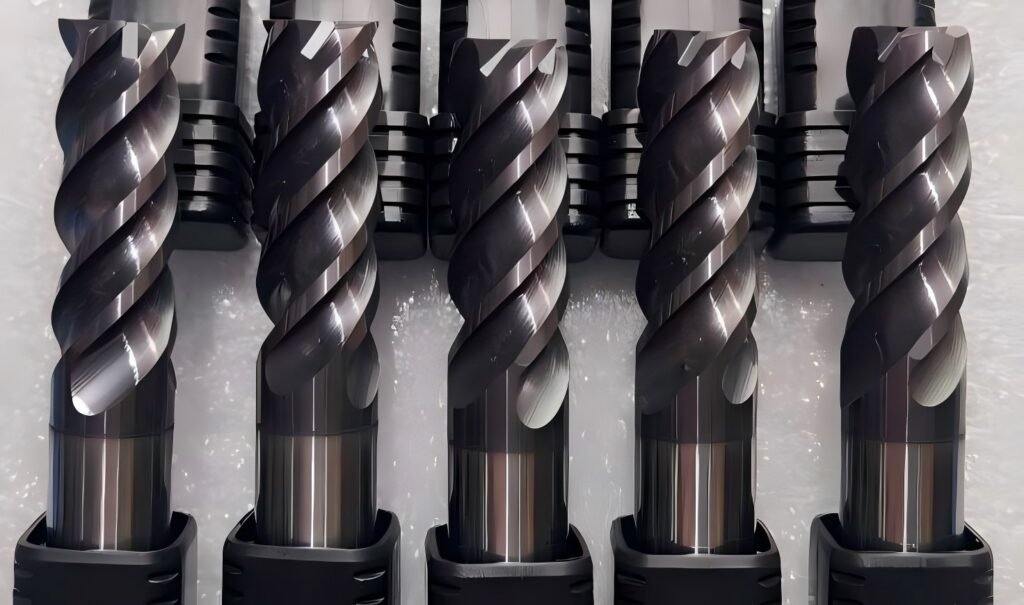
Product spotlight — HNCarbide DIN-Standard End Mills
Well-managed TLPs and TCPs shine most when paired with tools designed for repeatable offsets, stable deflection, and clean engagement.
Why DIN standards help
DIN geometry and shank tolerances (e.g., DIN 6527 for flute lengths and DIN 6535 for shanks) ensure stable gauge lengths and fit. That consistency shortens tool preset time, reduces length variability, and keeps the TLP where your offsets expect it—particularly when swapping tools measured offline.
Core portfolio matched to real jobs
Variable-pitch 5-flute square end mills (DIN): Micro-grain carbide, variable pitch/helix for chatter suppression in steels and stainless. Coatings such as AlTiN or AlTiN-Si extend life at elevated temperatures. Ideal when you rely on a fixed safe plane and need predictable deflection at high feed.
4-flute corner-radius mills (DIN): Added edge strength for stainless and tool steels; corner radii from R0.2 to R2.0 support size control via small wear offsets rather than reposting CAM paths.
High-polish aluminum mills (DIN): High-positive rake and wide flutes for effortless chip evacuation; optional TiB₂ coating. Keeps forces low, which stabilizes the TLP under fast transitions near clamps.
Shanks: Straight DIN shanks and Weldon-flat options for mechanical holders where axial security and repeatable gauge length matter.
Application support
We provide preset sheets (nominal gauge length and recommended stick-out) and suggested safe-plane clearances for typical fixtures, helping you standardize TLP measurement and TCP placement across product families.

Final checklist you can apply today
Decide and publish a single convention for ball-nose TLP (apex or center) and stick to it in both CAM and the control.
Choose touch-off points that make programming and inspection trivial—prefer functional datums or fixture features that are dimensionally tied to them.
Define a conservative TCP that clears every tool you own, then document it on the setup sheet.
Measure offsets consistently with the same reference plane and process; don’t mix methods mid-job.
Treat thin-wall clamping first, then set zeros; re-verify after any clamping change.
Standardize tools—DIN-compliant cutters with consistent gauge lengths and known deflection behavior make offsets honest.
Get these right, and most “mystery errors” disappear. The machine always knows where the tool is (TLP), it always swaps in a safe place (TCP), and your zero flow is simple enough that anyone on the team can reproduce it confidently—especially when paired with consistent, DIN-standard HNCarbide end mills.

