
Turning Process Engineering Guide
Tool Geometry, Core Equations, Cutting Forces, and Holder Rigidity—A Closed Loop from Design to Selection
Table of Contents
Why a closed loop matters
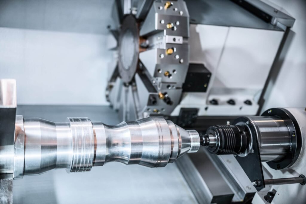
Successful turning is never just about picking an insert and pushing cycle start. A stable, efficient process links three decisions in sequence:
Design – clarify tool geometry in the triangular projection system so angles and edge features are unambiguous.
Calculation – select cutting speed and spindle speed, estimate feed and depth of cut, and check machine power.
Selection – size the toolholder/bar for stiffness using force estimates; then confirm that geometry and parameters deliver the required surface finish and tool life.
This article follows that exact “design → calculation → selection” loop. It distills what a process engineer needs on the shop floor: definitions that match drawings, equations that match units, and rules that keep chatter and edge failure away.
Nomenclature and effects of turning-tool geometry (triangular view)
In the tri-view convention used by most insert-tool catalogs, the following angles and radii are primary. Understanding how each influences chip formation, force direction, temperature, and finish allows you to tune the whole system.
Rake angle (γ, front rake)
Angle between the rake face and a reference plane.
Effect: higher positive rake lowers cutting force and cutting temperature, promotes soft, continuous chips, and is favored for stainless and nonferrous alloys. Negative rake strengthens the edge for heavy interruptions and cast irons.
Typical use: +10° to +20° for aluminum; +5° to +12° for stainless finishing; 0° to −7° for roughing steels/cast irons with strong negative-style holders.
Relief/clearance angle (α)
Angle between the clearance face and the work surface.
Effect: prevents flank rubbing and built-up heat; too small → friction & poor finish; too large → weak wedge and notch wear.
Typical bands: finishing 7–10°, general 6–8°, heavy roughing 5–7° (stronger wedge).
Approach (lead) angle (κr, “major cutting-edge angle”)
Angle between the major cutting edge and the feed direction.
Effect: It redistributes the cutting force. A smaller κr (~45°–60°) pushes more load axially (feed direction), improving chip-thinning and permitting higher feeds. A larger κr (75°–95°) directs more force radially into the work and holder; good for shoulders but can excite chatter on slender parts.
Rule of thumb: choose smaller κr for long overhangs and thin-walled parts.
End cutting-edge angle (κ’ r)
Clearance for the secondary edge. Too small risks rubbing on the newly machined surface; too large removes support near the nose.
Inclination angle (λs)
Tilt of the cutting edge relative to the work’s tangent.
Effect: controls chip flow left/right, affects contact length and edge entry. Slight negative inclination (−5° to 0°) stabilizes the edge in turning steel; positive inclination aids chip evacuation on aluminum.
Nose radius (re)
The round at the corner.
Effect: larger radii improve finish and share load, but raise radial force; small radii reduce radial load and help avoid chatter on thin parts but become fragile if feed is high.
Pairing rule: feed per revolution f should be 1/3–2/3 of re to maintain a consistent profile without plowing.
Effective rake
The actual rake seen by the chip after mounting (holder geometry + insert rake). A neutral insert can produce positive or negative effective rake depending on holder seat and inclination.
These parameters do not act alone. For example, choosing a bigger nose radius without increasing holder stiffness usually backfires because the radial component of cutting force rises.
Core equations for speed, feed, material removal, and power
All calculations assume metric units with consistent dimensions.
Cutting speed and spindle speed
Cutting speed VcV_cVc in m/min:
Vc=π D n1000V_c = \frac{\pi \, D \, n}{1000}Vc=1000πDn
Spindle speed nnn in rev/min:
n=1000 Vcπ Dn = \frac{1000 \, V_c}{\pi \, D}n=πD1000Vc
where DDD is workpiece diameter in mm at the cutting point.
Feed rate (table feed) in mm/min:
Vf=f⋅nV_f = f \cdot nVf=f⋅n
where fff is feed per revolution in mm/rev.
From force to stiffness: selecting a toolholder or boring bar
Even when power is sufficient, lack of stiffness ruins surface finish and tool life. Treat the holder or bar as a cantilever beam.
Cube and fourth-power effects matter: a small increase in shank height or bar diameter drastically cuts deflection.
Practical limits: aim for L/d≤4L/d \le 4L/d≤4 with steel bars; up to 6–7 with carbide or tuned damped bars. If the job forces a high overhang, reduce κr and nose radius, and lower feed until chatter fades.
Many catalogs visualize this choice with a “star” or “spider” chart linking feed, depth, overhang, and shank size. Read it as a map from anticipated force level to a minimum holder section.
Linking geometry to process parameters
These relationships help you move from drawing to stable parameters without trial-and-error overload.
Rake (γ) vs. material
Stainless and tough alloys benefit from positive rake and sharp edge prep to reduce work-hardening. Gray cast iron loves negative rake and robust honed edges. Aluminum prefers highly polished, high-positive rake with large chip space.
Approach angle (κr) vs. feed and surface
Small κr (45°–60°) spreads chip width, thinning chip thickness h≈fsinκrh \approx f \sin \kappa_rh≈fsinκr. That allows a higher feed for the same chip thickness and often improves tool life. However, on a shoulder or when holding a size against a face, you need κr closer to 90°.
Nose radius vs. finish and chatter
Finish improves as re increases for a given feed until radial forces excite vibration. A rule is f≤0.67 ref \le 0.67\, r_ef≤0.67re for clean cusps; for cosmetic finishing, f≈0.3−0.5 ref \approx 0.3{-}0.5\, r_ef≈0.3−0.5re.
Clearance angle (α) vs. flank wear
Too little α burns the flank; too much α weakens the wedge. Keep α moderate and use chip-breaker geometry to control contact—let the breaker, not the clearance, handle heat.
Chip breaker and coolant
Choose breakers by feed/depth window: “F” (finishing) for thin chips, “M” for medium, “R/H” for roughing. Adequate coolant flow helps stainless and heat-resistant alloys; dry or MQL is often best for gray cast iron and some high-speed aluminum finishing.
Parameter starting points by material family
Use these as engineering directions, not hard limits. Always reconcile with insert grade capability and machine constraints.
Carbon & low-alloy steels (ISO P)
Balanced κr (60–90°), moderate to negative rake for roughing, positive for finishing.
Workable range: VcV_cVc from 150–300 m/min with modern coated carbides; feeds 0.10–0.35 mm/rev for general work; depths 1–4 mm roughing, <1 mm finishing.
Stainless steels (ISO M)
Strong positive effective rake, sharp edge prep, controlled feed to avoid work hardening; high-pressure coolant if available.
VcV_cVc typically 80–200 m/min, feed 0.08–0.25 mm/rev.
Cast irons (ISO K)
Negative rake acceptable, interrupted cuts tolerated; dry cutting common.
VcV_cVc 180–350 m/min; feed 0.15–0.40 mm/rev.
Nonferrous (ISO N, e.g., aluminum)
Very positive rake, polished edge, large chip gullets; avoid BUE with proper speed and MQL or flood as needed.
VcV_cVc 400–1000+ m/min with PCD or polished carbide; feed 0.10–0.40 mm/rev based on rigidity.
Hardened steels (ISO H)
Small depths and feeds, rigid setup, CBN or cermet finishing.
VcV_cVc 120–250 m/min (CBN, light DOC), feed 0.05–0.20 mm/rev.
Practical checklists
Before cutting
Confirm diameter at the cut and compute nnn from VcV_cVc.
Validate that Pm≤P_m \lePm≤ machine continuous power; keep 10–20% margin.
Pick κr for the feature (lower for long overhang or thin walls; higher for shoulders).
Choose insert nose radius to match target feed and finish.
Select chip-breaker window that embraces your apa_pap-fff pair.
During optimization
If you hear chatter: shorten overhang, increase shank section, reduce rer_ere, lower κr, or drop feed slightly before touching VcV_cVc.
If flank wears fast: confirm α is not too small, verify runout, and reduce rubbing by raising feed a notch.
If crater wear dominates: lower VcV_cVc or move to a higher hot-hardness grade/coating.
If chips bird-nest: step up chip-breaker class or raise feed into the breaker’s design window.
Product spotlight — HNCarbide Turning Inserts
To translate the above method into dependable production, insert quality and geometry range matter. HNCarbide supplies a complete portfolio engineered around the geometry–force–rigidity loop.
Grades and targets
HC2015 / HC2025 / HC2035 (ISO P steels) – from finishing to heavy roughing. Multilayer CVD with Al2_22O3_33/TiCN/TiN and controlled-edge hone. 2015 shines at high-speed finishing; 2025 is the all-rounder; 2035 absorbs shock in interrupted cuts.
HM1125 (ISO M stainless) – nano-PVD with high adhesion, sharp but supported cutting edge to suppress work hardening and notch wear.
HK3515 (ISO K cast irons) – negative rake strength, crater-wear resistant CVD stack, tuned for dry/air cutting at high speed.
HA1010 (ISO N aluminum) – mirror-polished PVD, high-positive rake chipformers, ultra-low BUE.
HB7010 (ISO H hardened finishing) – cermet/CBN-tipped options for 55–62 HRC finishing where low Ra is mandatory.
Chipformers
F (finishing): stable at low feeds, clean topography for Ra < 1.6 µm.
M (medium): broad window for general turning; resists chip birds’ nests on stainless.
R/H (roughing/heavy): deep groove, strong wedge, handles large apa_pap and interrupted cuts.
Wiper-edge variants are available to maintain fine surface at higher feed.

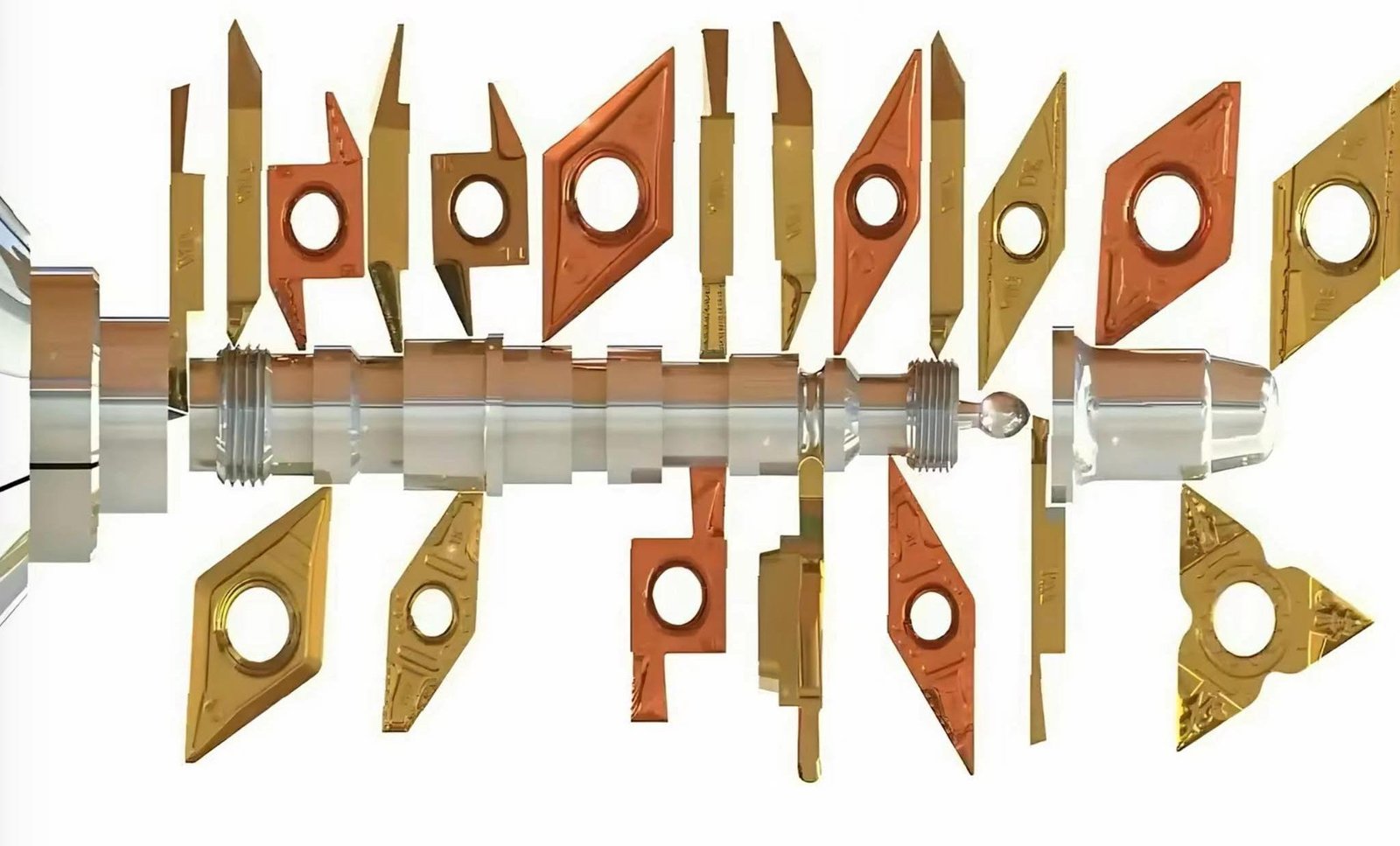
Geometries
Standard CNMG/WNMG/DNMG/VNMG/CCMT/TCMT families, along with positive clearance versions for small machines. Polished, high-positive ISO-N inserts for aluminum and copper alloys. Special ground periphery and edge preps on request.
Selection mapped to the engineering loop
Pick grade by material and coolant condition.
Choose κr and nose radius for the feature and rigidity.
Set apa_pap–fff in the chipformer’s window; compute VcV_cVc and nnn.
Estimate FcF_cFc and verify holder stiffness; if L/dL/dL/d is high, use HNCarbide’s carbide or damped bars to push the stability boundary.
Iterate with our recommended starting speeds—then lock the recipe with tool life data.
Support
HNCarbide’s application engineers can translate your unit-power table into shop-specific constants and provide force-based holder sizing charts so your programming team can standardize the “design–calculation–selection” loop across parts and lines.

