
End Mill Tool Life Explained: 10 Real-World Ways to Make Your Tools Last Longer
Table of Contents
When a cutting tool end mill fails early, the symptoms are obvious—burnt edges, chipped corners, poor surface finish, or even a scrapped part. What is often less clear is why the failure happened and how similar problems can be avoided in future jobs.
End mill tool life is influenced by many interacting factors, from cutting data and tool geometry to toolholding, coolant strategy, and machining approach. These principles apply equally to premium tools from established brands, mid-range industrial cutters, and cost-effective China cutting tool end mills.
This article explains end mill tool life in practical shop terms and outlines ten proven factors that directly affect how long an end mill cutting tool lasts in real CNC production.
What Is End Mill Tool Life?
End mill tool life is the usable cutting time or cutting distance a tool delivers before it must be replaced or reconditioned. In modern machining, tool life is typically defined by wear limits rather than catastrophic breakage.
Common Wear Types
End mills usually fail through one or more of the following mechanisms:
Major Wear Modes on an End Mill
Wear Type | Where It Appears | Typical Cause | Effect on Process |
Flank wear | Relief face behind edge | Normal abrasion, long cutting time | Loss of size control, higher cutting forces |
Crater wear | Rake face near edge | High temperature, chemical wear | Edge weakens and chips |
Micro-chipping | Cutting edge or corner | Vibration, hard inclusions | Surface lines, sudden failure |
Built-up edge | Material welded to edge | Incorrect cutting data, poor lubrication | Poor finish, edge breakage |
When Is a Tool Worn Out?
An end mill is considered worn out when one or more of the following conditions occur:
- Dimensional tolerance can no longer be maintained
- Surface finish falls below specification
- Flank wear reaches a defined limit (typically 0.2–0.3 mm on carbide)
- Edge or corner chipping becomes visible
In production environments, tools are commonly removed before catastrophic failure and sent for reconditioning using professional grinding services or end mill tool grinders.
Correct Cutting Data
Cutting parameters have a greater influence on carbide end mill tool life than almost any other single factor.
RPM, Feed per Tooth, and Depth of Cut
Three parameters define cutting conditions:
- Cutting speed (SFM or m/min)→ determines spindle RPM
- Feed per tooth (fz)→ chip thickness per cutting edge
- Axial and radial depth of cut (ap, ae)→ chip engagement
Excessive speed with insufficient chip load causes rubbing and heat buildup. Too much chip load at low speed overloads the edge and leads to chipping or breakage.
Using Cutting Data Tables
Most reputable tool manufacturers publish starting values for specific materials. These values establish a baseline that can be adjusted based on machine rigidity, toolpath, and setup stability. Tracking tool life in parts produced or cutting distance makes long-term optimization possible.
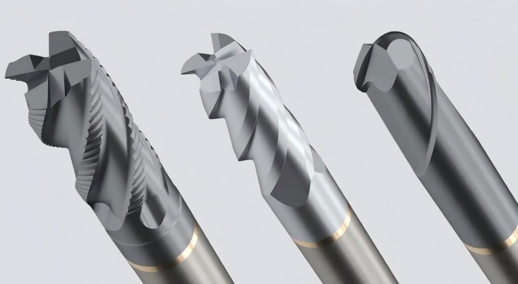
End Mill Tool Geometry
End mill tool geometry defines how the cutter interacts with the workpiece. A geometry matched to the material can dramatically increase tool life.
Matching Helix Angle and Flute Count
- Aluminum:2–3 flutes, high helix (40–55°), large flute space
- Carbon and alloy steel:3–4 flutes, standard or variable helix (30–40°)
- Stainless and super alloys:4–6 flutes, variable helix to reduce chatter
- Hardened tool steel:4–6 flutes, strong core, small corner radius or ball end mill tool
Incorrect flute count or helix angle often leads to chip packing, vibration, and localized edge failure.
Edge Preparation and Corner Design
- Sharp edges cut freely but chip quickly in hard materials
- Honed edges tolerate higher loads and abrasive conditions
- Corner radius designs significantly reduce stress at the cutting edge
- Nano coated end mill tools for hard materials typically combine honed edges, corner radius, and advanced coatings for durability
Tool Holder and Runout
Runout—the deviation between the tool’s rotational axis and the spindle centerline—has a major impact on tool life.
Why Runout Shortens Tool Life
With measurable runout:
- One flute carries most of the cutting load
- That flute overheats and wears prematurely
- Remaining flutes then fail in sequence
This leads to early tool replacement even though most cutting edges remain lightly worn.
Holder Quality and Accuracy
Low-runout end mill tool holders—such as shrink-fit, hydraulic, or high-precision collet systems—distribute load evenly across all flutes. Drill chucks and worn tapers are common sources of premature wear.
Machine Rigidity and Setup
Tool life depends heavily on machine stiffness and workpiece stability.
Fixturing and Vibration
- Rigid fixturing reduces chatter and micro-chipping
- Supporting thin parts minimizes vibration and spring-back
- Short spindle-to-part distance improves stability
Tool Overhang
Long overhang increases deflection exponentially. Using the shortest possible tool length often improves end mill tool life more than changing coatings or cutting data.
Coolant and Lubrication
Cooling strategy must match both material and cutting method.
Flood, MQL, and Dry Cutting
- Flood coolant:Effective for steels and stainless steels when properly applied
- Mist / MQL:Provides lubrication where flood is impractical
- Dry cutting:Common with AlTiN-coated carbide in high-speed steel machining
Many modern nano coated end mill tools are designed to operate with air blast or minimal lubrication.
Chip Evacuation and Built-Up Edge
In aluminum and soft alloys, poor chip evacuation causes built-up edge. This results in unstable cutting, poor surface finish, and sudden edge breakage. High-helix geometry and polished flutes help prevent this condition.
Cutting Strategy and Toolpath
Toolpath selection strongly influences cutting forces and thermal load.
High-Efficiency Milling (HEM)
HEM strategies use:
- Small radial engagement
- Large axial depth
- Higher feed per tooth
This maintains consistent chip thickness and reduces heat concentration, significantly extending tool life in steel and stainless steel.
Climb vs Conventional Milling
Climb milling produces less rubbing, lower cutting forces, and better surface finish in most CNC applications. Conventional milling is typically reserved for special situations involving thin parts or machine backlash.
Improving Tool Life in Steel
Material: 1045 steel
Tool: 10 mm carbide flat end mill tool
Initial Conditions
- General-purpose 4-flute TiN-coated carbide
- Standard ER collet holder
- Full-slotting, 1×D depth
- Conventional milling
- Tool life: ~40 parts
Optimized Conditions
- Variable-helix AlTiN nano coated end mill for tool steel
- High-precision hydraulic holder
- High-efficiency milling strategy
- Climb milling
Tool Life Comparison
Parameter | Before | After |
Average parts per tool | 40 | 140 |
Surface finish (Ra, µm) | 1.6–2.0 | 0.8–1.2 |
Failure mode | Corner chipping | Gradual flank wear |
Tool cost per 1,000 parts | Higher | 40–50% lower |
What Really Extends End Mill Tool Life
Long end mill tool life results from controlling multiple factors simultaneously:
- Correct cutting data
- Geometry matched to material
- Low-runout toolholding
- Rigid machine setup
- Proper coolant and chip evacuation
- Efficient cutting strategies
- Consistent inspection and replacement practices
Whether using premium brands, specialty micro tools, or high-value China cutting tool end mills, these principles determine how much usable life each cutting tool delivers.

