 Skip to content
End Mill Tool Geometry: How Helix, Flutes, and Corners Control Your CNC Results
Table of Contents
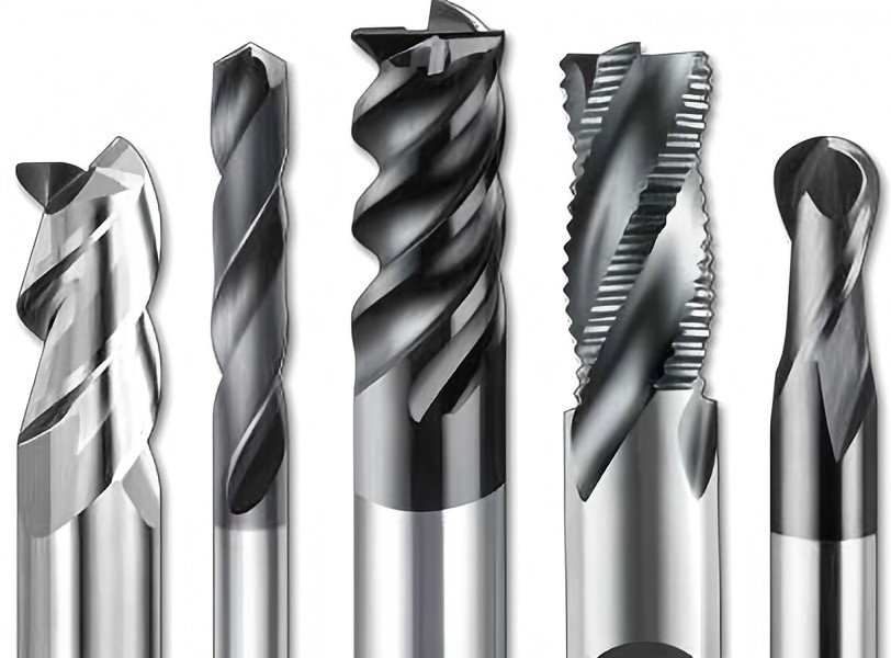
If parts chatter, burn, or come out slightly undersized, the cause is often not CAM programming but end mill tool geometry.
Two tools with the same diameter and coating can behave very differently if their helix angle, flute count, core design, and corner geometry are not matched to the application. Understanding these details directly impacts surface finish, dimensional accuracy, and end mill tool life—regardless of whether the cutter comes from a premium European brand, a Fullerton tool end mill, an HTC tool end mill, or a high-value China cutting tool end mill.
This article explains end mill geometry in practical terms, focusing on how specific design choices affect real CNC machining results.
Why End Mill Tool Geometry Matters
Tool geometry determines how spindle power is converted into chip formation. Small changes in angles and radii directly influence:
- Cutting forces and spindle load
- Vibration and chatter behavior
- Chip size and chip evacuation
- Heat generation and wear patterns
When geometry is well matched to the material and operation, carbide end mill tool life can increase significantly while surface finish improves. Poor geometry often forces reduced feeds, shallow step-overs, and extra finishing passes—lowering overall productivity.
Flute Count Basics
Flutes are the helical grooves that create cutting edges and chip channels. Increasing flute count adds cutting edges but reduces available chip space.
2-Flute vs 3-Flute vs 4-Flute (and More)
2-Flute Flat End Mill Tool
- Very large chip space
- Ideal for aluminum, plastics, and slotting
- Performs well in ramping operations
- Lower stiffness than higher flute counts
3-Flute End Mill
- Common in aluminum and softer steels
- Balanced chip space and rigidity
- Frequently used for high-speed aluminum machining
4-Flute Tool End Mill
- Standard choice for steel and stainless steel
- Stronger core and better finishing stability
- Reduced chip space; requires controlled radial engagement
5–7 Flutes
- Designed for finishing steel, stainless, and super alloys
- High metal removal with small step-overs
- Best suited for rigid machines and precision holders
Typical Flute Count by Material
Material / Operation | Recommended Flute Count | Notes |
Aluminum, non-ferrous (slotting) | 2–3 | Large chip space, polished flutes preferred |
Aluminum (finishing) | 3–4 | Improved surface finish |
Mild & alloy steel | 3–4 | 4-flute commonly used |
Stainless steel | 4 | Controlled chip size, stronger core |
Hardened steel / tool steel | 4–6 | Lower chip load per tooth |
Titanium & super alloys | 4–6 | Variable flute spacing often applied |
Effective chip evacuation remains critical. When chips cannot escape, tool failure follows regardless of coating quality.
Helix Angle Explained
The helix angle is the angle between the cutting edge and the tool’s centerline. It controls cutting smoothness, chip flow, and axial forces.
Low, Standard, and High Helix
Low Helix (20–30°)
- Thick core and strong cutting edges
- Lower axial cutting forces
- Suitable for hard or abrasive materials
- Performs well in interrupted cuts
Standard Helix (30–40°)
- General-purpose range for many steels
- Balanced strength and chip evacuation
High Helix (40–55° or higher)
- Smooth cutting action
- Excellent chip evacuation
- Common in aluminum and stainless steel
- Generates higher axial pull-up forces
High-helix designs are frequently combined with nano coated end mill tool technology to allow higher feed rates while maintaining tool life.
Chip Evacuation vs Rigidity
Higher helix angles improve chip flow but introduce trade-offs:
- Reduced core thickness
- Increased axial force on the tool
- Greater sensitivity to toolholding quality
Moderate helix designs often provide better stability on less rigid machines.
Core Diameter and Relief
The core diameter is the solid center of the tool, while relief is the clearance behind the cutting edge.
Tool Strength
- Large core diameter improves stiffness and resistance to bending
- Smaller core provides more flute space but increases deflection risk
In micro and long-reach tools, core design becomes especially critical to prevent breakage at very small chip loads.
Chip Space and Cutting Forces
Excessively large cores limit chip evacuation. For example, aluminum slotting with a high-flute, heavy-core cutter often leads to built-up edge and tool failure.
Key indicators on a spec sheet include:
- Core diameter as a percentage of cutting diameter
- Web thickness
These values indicate whether a tool favors roughing strength or finishing efficiency.
Corner Design Options
The corner of an end mill is a common failure point. Corner geometry has a major influence on tool life and part quality.
Square, Corner Radius, Ball, and Chamfer
Square End
- Sharp internal corners
- Maximum reach
- Fragile edge, prone to chipping
Corner Radius
- Small radius (0.2–1.0 mm) strengthens the edge
- Ideal for steel and stainless steel
- Leaves a controlled internal fillet
Ball Nose (Ball End Mill Tool)
- Used for 3D contouring and mold work
- Zero surface speed at the center
- Toolpath strategy is critical
Chamfer
- Used for deburring and edge breaking
- Improves strength on roughing tools
Effect on Part Quality
Corner design influences:
- Stress concentration at part edges
- Burr formation and edge chipping
- Surface blending in 3D profiles
A small corner radius often improves both tool life and part durability in hard materials.
Special Geometry Features
Modern high-performance end mills often include additional geometry refinements.
Variable Helix and Variable Pitch
Variable designs disrupt cutting harmonics:
- Slightly different helix angles per flute
- Uneven flute spacing
- Reduced vibration and chatter
This allows higher feed rates and improved finishes, particularly in steel and stainless steel.
Roughing (“Corncob”) Profiles
Roughing end mills feature serrated cutting edges:
- Smaller, broken chips
- Lower cutting force spikes
- Efficient heavy stock removal
A common approach is roughing with a serrated cutter, followed by finishing with a standard or corner-radius flat end mill tool.
Understanding End Mill Geometry Specifications
A complete geometry specification typically includes the following parameters:
Parameter | Typical Notation | Function |
Cutting diameter & shank | ØD, Ød | Tool fit and chip load |
Overall length & flute length | L, Lc | Reach and rigidity |
Flute count | Z | Chip space vs stiffness |
Helix angle | λ | Chip flow and force direction |
Corner radius / style | RE, CR | Edge strength |
Core diameter / web | – | Tool stiffness |
Relief & rake angles | α, γ | Cutting smoothness |
Coating | TiAlN, AlTiN, DLC, etc. | Heat and wear resistance |
Recommended materials | – | Geometry optimization |
Practical Geometry Examples
Tool Steel Machining (H13, D2, 54–60 HRC)
Typical geometry characteristics:
- Solid carbide substrate with advanced heat-resistant coating
- 4–6 flutes with variable helix (≈35–40°)
- Strong core with controlled chip space
- Small corner radius or ball nose for 3D work
This configuration delivers stable cutting and consistent surface quality in hardened steels.
Aluminum and Stainless Steel Applications
High-Speed Aluminum Pocketing (6061)
- 3-flute flat end mill tool
- High helix (~45°)
- Polished flutes or DLC coating
Stainless Steel Profiling (316)
- 4-flute variable helix design
- 35–40° helix
- Strong core with small corner radius
In both cases, geometry is tailored to chip behavior rather than relying on a general-purpose cutter.
Toolholding and Geometry Stability
Even optimized geometry depends on stable toolholding. Runout, grip strength, and cleanliness all affect cutting performance and wear consistency.
Consistent maintenance and appropriate holder selection are essential for achieving predictable results from any end mill cutting tool.

Conclusion
End mill tool geometry defines how a cutter interacts with material.
By understanding helix angle, flute count, core design, and corner geometry, machinists can:
- Improve surface finish and dimensional accuracy
- Reduce chatter and unpredictable wear
- Extend carbide end mill tool life
- Compare different tool brands and series more effectively
Whether using premium imports or cost-effective China cutting tool end mills, geometry remains the foundation of reliable CNC performance.


