 Skip to content
Climb vs. Conventional Milling & Smart Toolpaths: A Practical Guide for CNC Machining
Table of Contents
Introduction — Why milling direction and toolpaths matter
Whether you’re roughing a pocket or finishing a sealing surface, cut direction and path strategy determine tool life, dimensional control, and the “feel” of your process. Choose poorly and you’ll fight chatter, burrs, and erratic forces at every corner. Choose well and you’ll run faster with less wear, smoother sound, and repeatable surface finish.
This guide demystifies:
- Peripheral milling(round-the-cutter) vs. face milling(end face engagement).
- Conventional/Up millingand Climb/Down milling—when each is appropriate.
- How to program “clockwise vs. counter-clockwise” so the machine actually cuts the way you intend.
- Corner behavior, Z-plunge risks, and why ramp/helix entries protect tools.
- How end-mill geometry influences residual stock on pocket walls.
- Practical HNCarbide tooling options that make these methods robust on the shop floor.
Definitions you can use on the floor
- Peripheral (cylindrical) milling:The side of the cutter produces the surface.
- Face milling:The cutter’s end face (and a bit of the periphery) produces the surface.
- Conventional (up) milling:Workpiece feed is opposite the cutter’s rotation at the contact point. Chip thickness starts at zero and increases.
- Climb (down) milling:Feed is the same direction as rotation at the contact point. Chip starts thick and leaves thin.
What this means for forces and the part
In conventional milling, the edge first rubs/presses, then begins to cut. This raises heat, encourages work-hardening, and can lift thin walls. In climb milling, the edge bites immediately at maximum thickness, reducing rubbing and keeping the resultant force pressing into the table—good for surface quality and tool life when the machine is tight.
Choosing climb or conventional in peripheral milling
Rules of thumb
Use climb milling whenever the machine has low backlash (modern CNC with preloaded ballscrews), workholding is rigid, and the surface is scale-free. Expect lower cutting temperature, smaller burrs, and longer tool life.
Use conventional milling when the work surface has scale/skin (castings, flame-cut edges), the setup is delicate, or backlash is a concern on older machines. Entry shock is gentler on brittle edges in hard skin.
Quick comparison you can paste into your process sheet
Topic | Climb (down) milling | Conventional (up) milling |
Chip thickness profile | Starts thick → ends thin | Starts zero → ends thick |
Edge loading & heat | Less rubbing, cooler | More rubbing, hotter |
Table/part force | Pushes into table (stable on rigid setups) | Tends to lift work (risk on thin walls) |
Surface with scale | Can chip edges on skin—avoid | Safer; edge enters from clean side |
Backlash sensitivity | Needs minimal/zero backlash | More tolerant on older machines |
Typical use | CNC production, finishing | Roughing on hard skin, legacy machines |
How to program directions without second-guessing
“Which way is climb” gets confusing because CAM and textbooks assume a stationary part and moving tool, while on the machine the tool spins and the table feeds. Use these programming heuristics:
External contours (profiles):
- Program clockwise (CW)to get climb.
- Program counter-clockwise (CCW)to get conventional.
Internal contours (pockets/bores):
- Program CCWto get climb.
- Program CWto get conventional.
Face milling: symmetric vs. asymmetric engagement
Face milling can be arranged so the cutter centerline is centered on the stock or offset to favor climb or conventional engagement.
Centered (symmetric) face milling balances climb and conventional within one pass—useful on short, wide parts but not ideal for long thin plates.
Offset toward conventional (more up-milling) increases rubbing and edge heat—tough on tools in difficult materials.
Offset toward climb minimizes rubbing and typically leaves the best finish and burr control—preferred on rigid CNCs.
Practical face-milling setup guide
Setup | Where to use | Benefits | Watch-outs |
Centered engagement | Short/wide or thick parts | Balanced forces; simple to program | Not ideal for thin plates (lift risk) |
Offset toward climb | General finishing on rigid machines | Lower heat, better burr control | Avoid on heavy scale; confirm backlash is near zero |
Offset toward conventional | Hard-skin stock, legacy machines | Gentler edge entry on skin | Higher heat/rubbing; shorter tool life |
Toolpath choices at corners and along Z
Sudden direction changes at corners create short bursts of over-engagement—your load meter will spike, especially with constant-velocity settings. Pure Z-plunge is also punishing: the tool center’s cutting speed is zero, so the edge rubs before it can shear.
Keeping the path planar in XY with smooth radius transitions stabilizes chip thickness and reduces shock. Where you must enter from the top, ramp or helix instead of plunging.
Entry strategies that protect the edge
Entry move | When to use | Pros | Cons |
Straight Z-plunge | Only with center-cut geometry, shallow depth, soft materials | Simple; minimal air-cut | Highest edge abuse; speed at tool center is zero |
Ramp (angled) | Most pockets/slots; limited space | Gentle entry; coolant reaches the cut | Needs clearance; plan angle to fit flute length |
Helix | Blind holes/pockets; deep entries | Best load distribution; reliable chip evacuation | Requires lead-in space; CAM post must support helix lead |
End-mill geometry and residual stock on pocket walls
Different cutters leave different wall scallops when step-downs don’t “stack” perfectly:
- Square end millstend to leave a stair-step residual; consistency depends on Z-step and runout.
- Corner-radius end millsreduce stress concentration and even out the residual—great for semi-finish.
- Ball-nose and lollipop toolsare invaluable for blending but demand stepover control; the center point has zero cutting speed, so avoid slow feeds at the tip.
Quick geometry–application cheat sheet
Geometry | Best roles | Why it works | Notes |
Square | Roughing; sharp corners | Maximizes MRR; simple | Burrs and steps—leave stock for finishing |
Corner-radius | Semi-finish & roughing tough alloys | Stronger edges; smoother residual | A good “daily driver” for pocket floors/walls |
Ball-nose / lollipop | 3D surfacing & blend zones | Continuous curvature; excellent blending | Avoid on-center dwell; raise feed near the tip |
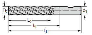
DIN Milling Cutters Catalog
Click the button below to view our DIN milling cutters catalog and explore detailed product specifications to make the best choice.
Putting it together: recommended programming patterns
Roughing pockets: climb in XY with constant tool engagement; use trochoidal or adaptive paths to avoid corner overload. Ramp or helix into material; never straight plunge unless geometry is center-cut and depth is small.
Finishing walls: climb with a spring pass (light radial, full height) to average deflection. If the finish shows taper, split into two Z-segments.
Finishing floors: face-mill with an offset favoring climb; for narrow features use a corner-radius end mill to minimize burrs.
Thin walls/weak fixturing: consider conventional for roughing to avoid wall pull, then switch to climb for finish.
Hard skin/scale: conventional for the first skim, then climb for the remainder.
HNCarbide solutions for stable milling (and clean threads)
Carbide End Mills (Pro-Mill & Radius-Pro series)
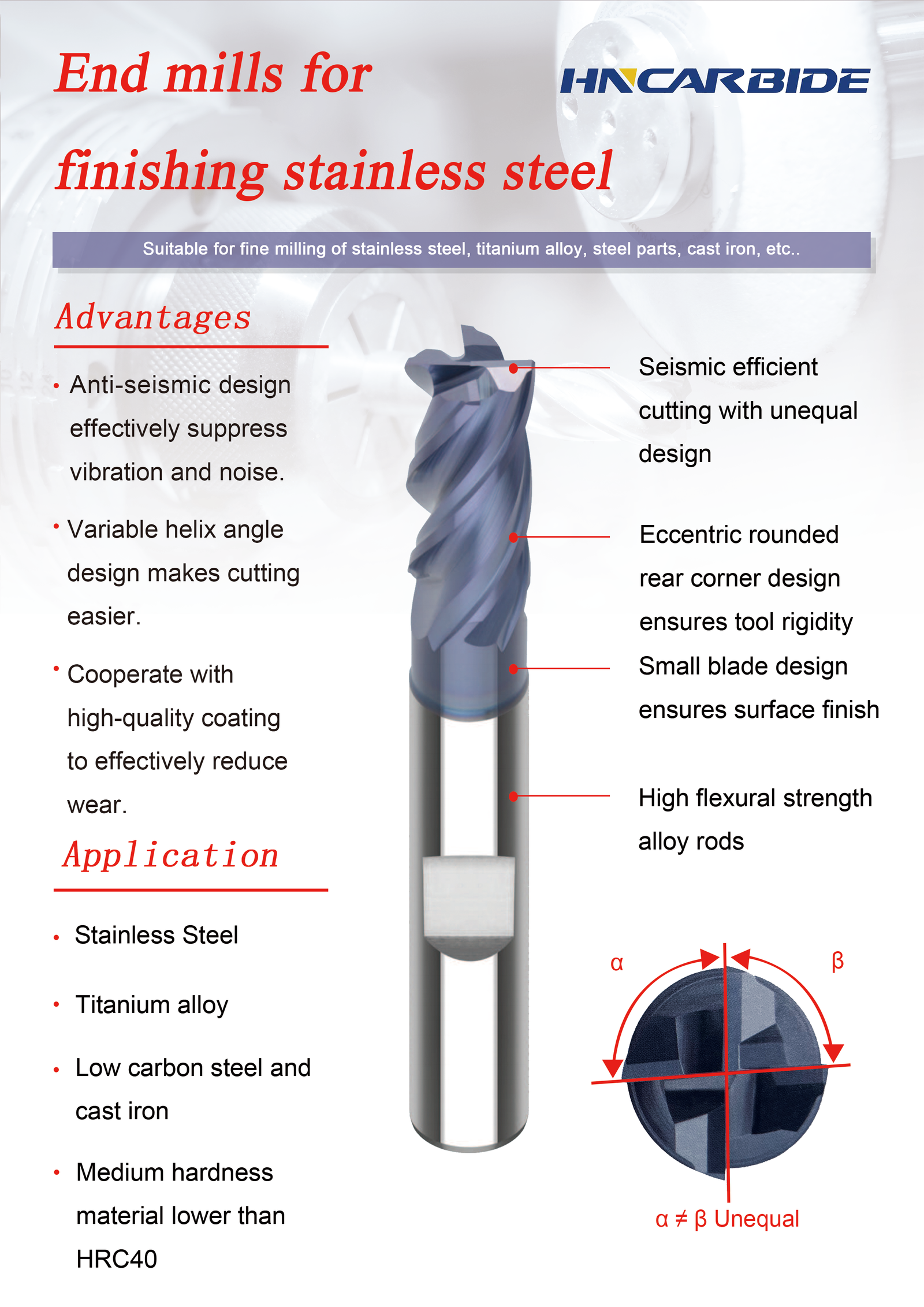
- Variable-pitch, variable-helix to suppress chatter on thin-wall parts.
- Corner-radius options for stronger edges and better residual stock behavior.
- Optional through-coolant micro-mills for heat-sensitive alloys.
Indexable Face Mills (HF-Climb family)
- Geometry tuned for climb-biased face milling and low burr floors.
- Positive rake inserts reduce spindle load and improve surface integrity.
Small-feature tools (Ball-Nose & Lollipop)
- Mirror-finish flutes and edge prep optimized for 3D finishing.
- CAM-friendly radii matched to common stepovers.
Related threading kits from HNCarbide: If your part also requires tapped holes, our threading lineup helps you keep the wins from smarter toolpaths all the way to assembly. We provide taps for cutting threads, high-stability cutting taps, and rigid-cycle cnc tap options. Matched tap drill sets make percentage-of-thread selection easy. Even though this article focuses on milling, threading reliability benefits from the same discipline—steady loads, correct entry, and the right geometry.
Worked example — From corner shock to smooth load
A pocket in 7075-T6 (8 mm deep, 10 mm tool, 12% radial, 2×D axial) showed torque spikes at each corner and visible burrs. We changed:
- path to adaptive climbwith 0.5×D corner radii,
- entry from plunge to 3° ramp,
- tool from sharp square to 0.5 mm corner-radius.
Results: spindle load variance fell by 40%, burrs disappeared, and tool life more than doubled. On the finishing pass, a single spring pass (0.05 mm radial) removed the residual taper.

Conclusion — The three levers that matter most
- Engagement direction:favor climbon rigid CNCs; use conventional only for hard skin or fragile setups.
- Path smoothness:keep motion planar with generous corners; swap plunges for ramp/helixentries.
- Geometry fit:pick end-mill shapes that suit the task (corner-radius for durability, ball-nose for blending) and adjust allowances for deflection.
Dialing in these three levers yields quieter cuts, better surfaces, longer tool life—and a process your operators can run confidently shift after shift.
FAQ
1.Does climb milling always finish better?
On rigid machines, yes—chip leaves thin, rubbing drops, and burrs shrink. On loose or backlash-prone setups, conventional may be safer until rigidity issues are solved.
2.Why do my corners sound “angry” even with light stepovers?
Instantaneous engagement spikes at sharp corners. Add corner radii, reduce max engagement, or use adaptive/trochoidal paths.
3.When should I helix instead of ramp?
Helix is superior for deep blind pockets when you have room for a circular lead-in and need steady loads plus clean chip evacuation.
4.Do ball-nose tools really cut at zero speed at the tip?
Yes—the center point has zero surface speed. Avoid dwelling there; keep feeds up and blend over the arc.


