CNC Router Bits for Wood A Practical Selection and Application Guide
Table of Contents
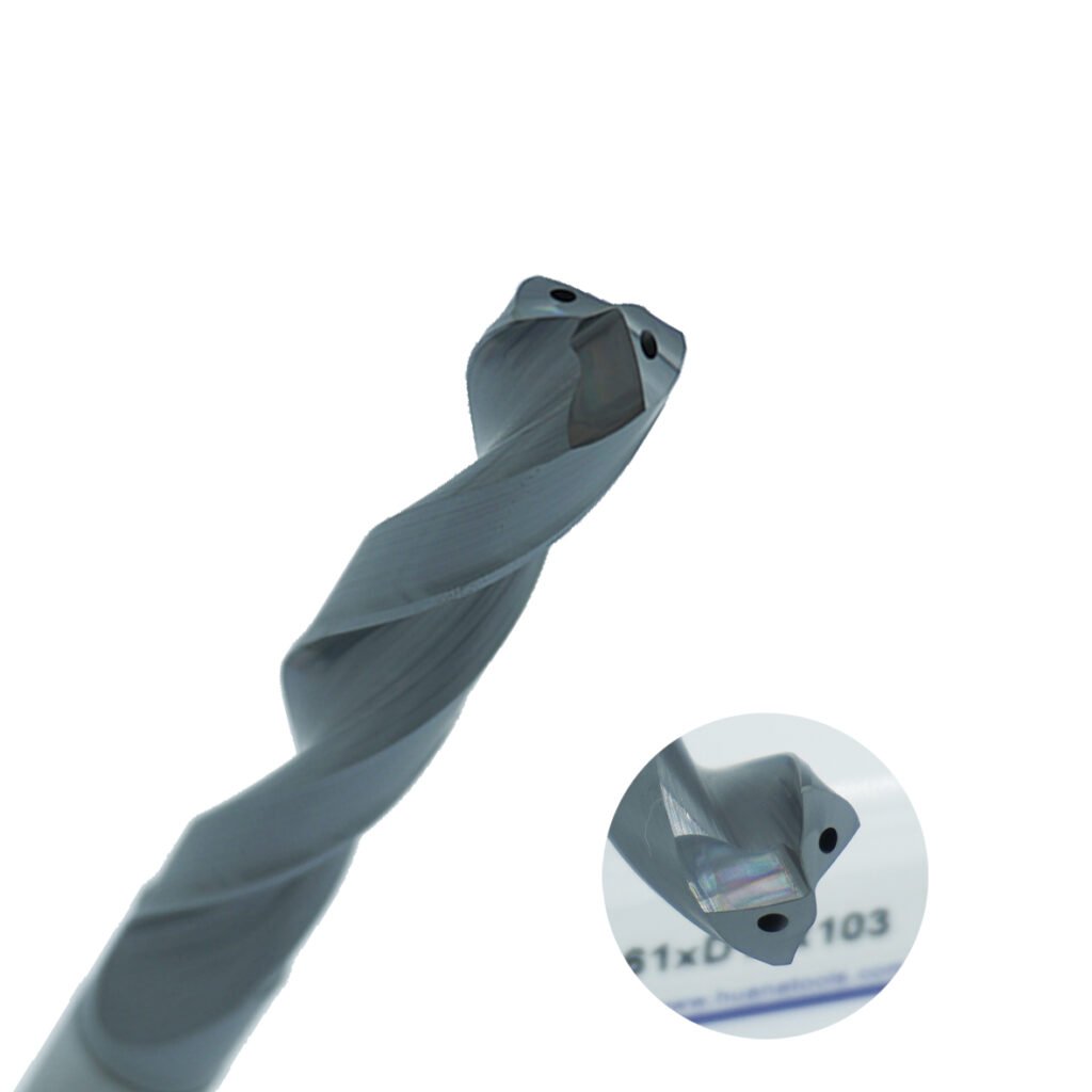
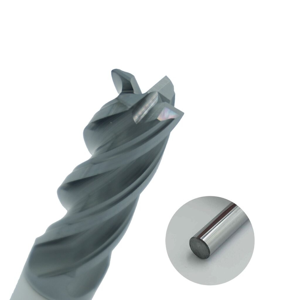
A CNC router can follow the programmed path perfectly and still produce chipped veneer, burned edges, fuzzy grain, or undersized parts. The cutter is often where the process succeeds or fails. Its flute direction controls chip flow and surface pressure. Its diameter and cutting length affect stiffness. Its edge geometry determines whether the tool shears wood fibers cleanly or rubs them into heat.
This guide focuses on production woodworking: plywood and laminated panels, MDF, solid hardwood, softwood, and common plastic sheet used in cabinet, furniture, sign, and fixture work. It explains how to choose a router bit, establish a safe starting process, and diagnose the cut before scrap begins to accumulate.
Start with the operation and the visible face
Bit selection is easier when the job is described as an operation rather than a material alone. Cutting a cabinet side from prefinished plywood, pocketing a hardwood tray, engraving a sign, and trimming a laminated edge all involve wood-based material, but they impose different loads and finish requirements.
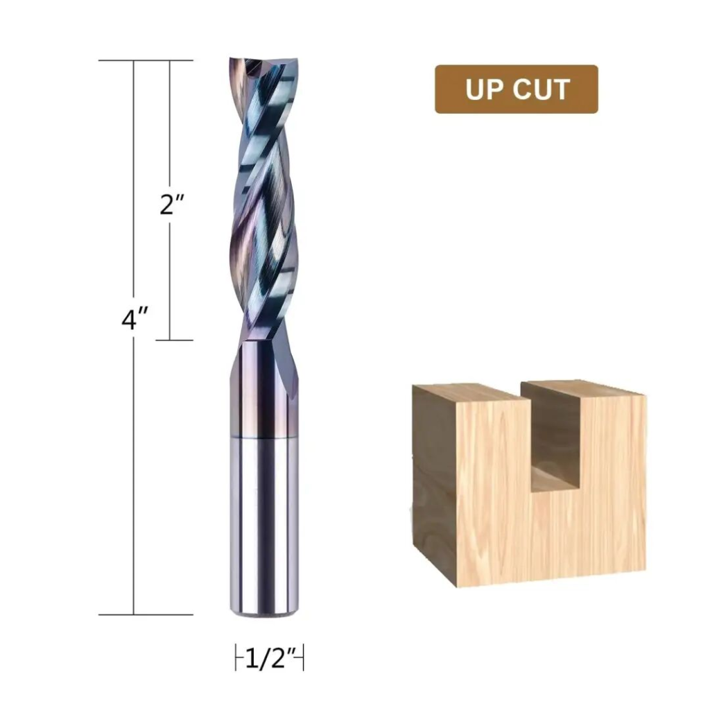
First identify which faces will remain visible. A downcut bit protects the top face because its helix pushes fibers toward the workpiece. An upcut bit clears chips efficiently and often leaves the bottom face cleaner, but it can lift weakly held parts and pull fibers from the top veneer. A compression bit combines both actions so the top and bottom faces are pushed toward the middle of the sheet. That makes it a strong choice for through-cutting veneered plywood or melamine, provided the first pass is deep enough to engage the correct flute zones.
The second question is whether the tool must plunge, slot, profile, pocket, or finish an existing wall. A bit that performs well in a light finishing pass may be a poor slotting tool because a full-width cut leaves less room for chips. The cutting length must also match the real depth of cut without forcing excessive stick-out from the collet.
Router bit types and where they fit
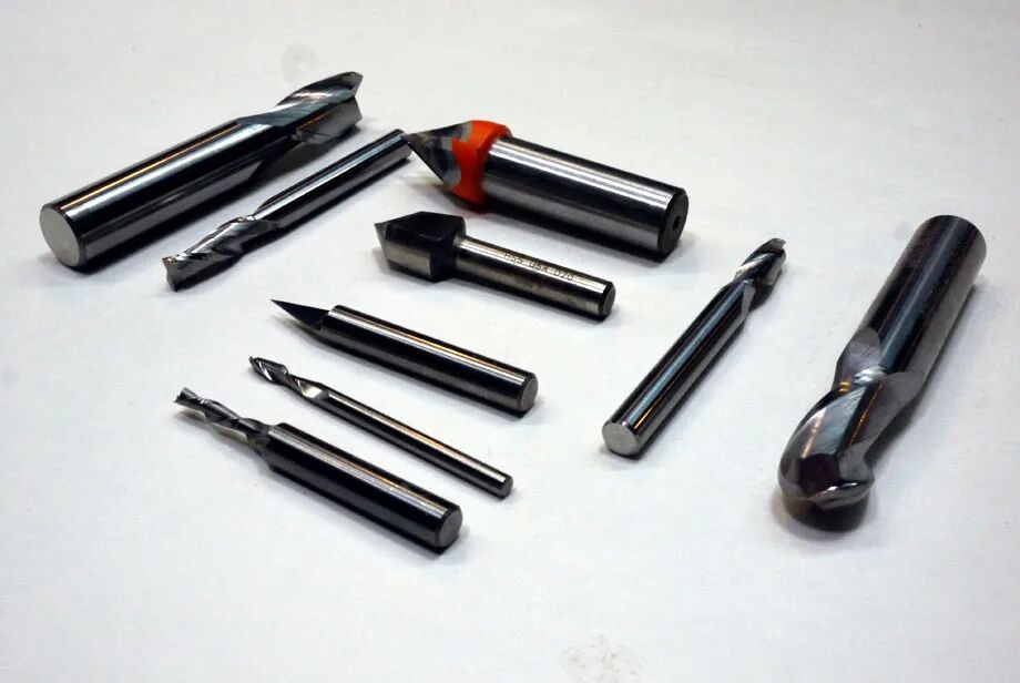
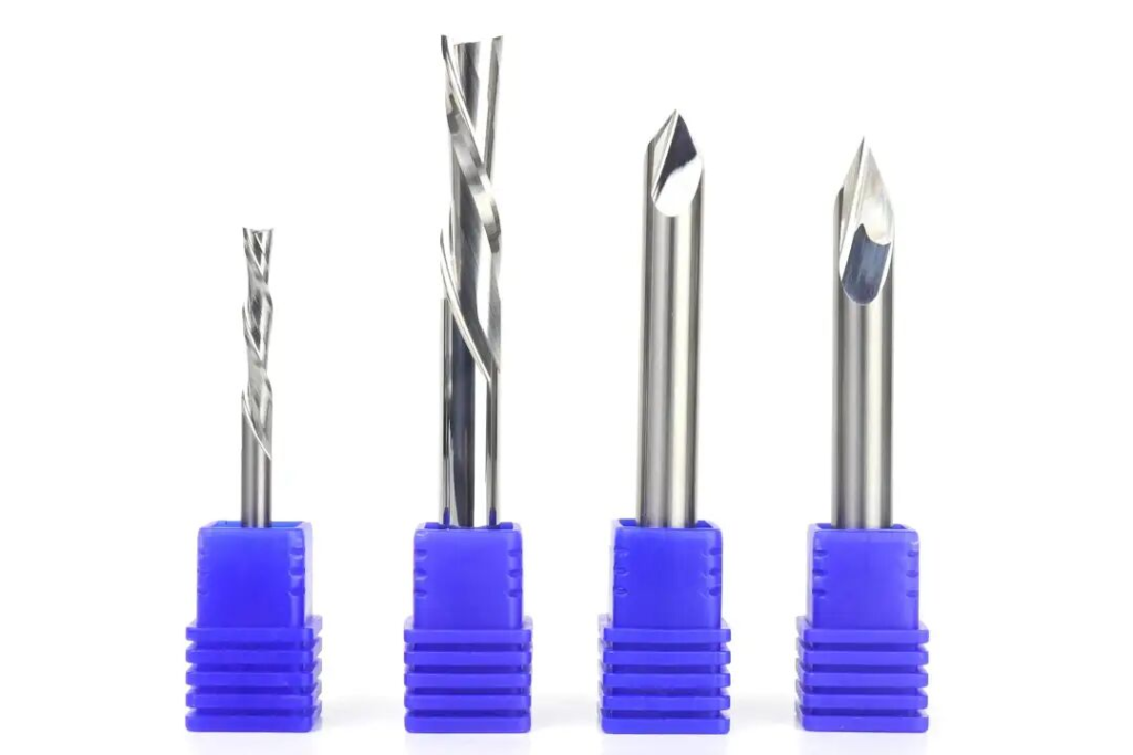
Router bit type | Typical woodworking use | Main advantage | Main limitation |
Straight flute | Shallow grooves, joinery, template work, simple trimming | Neutral axial force and predictable geometry | Chip evacuation and edge finish usually trail a good spiral bit in production CNC routing |
Upcut spiral | Deep grooves, pockets, hardwood routing, jobs that need strong chip removal | Pulls chips out of the cut and reduces recutting | Can fray the top face or lift a small part if hold-down is weak |
Downcut spiral | Shallow dados, visible top surfaces, thin parts | Leaves a cleaner top edge and presses the part down | Packs chips into blind grooves and can increase heat in deep cuts |
Compression spiral | Through-cuts in plywood, melamine, laminated panels | Protects both faces when both helix sections are engaged | First-pass depth and toolpath strategy must match the upcut length at the tip |
V bit | Lettering, engraving, chamfers, decorative grooves | Groove width changes with depth, which suits carved details | Runout or an incorrect Z zero changes line width visibly |
Ball nose | 3D reliefs, contoured surfaces, mold patterns | Produces smooth transitions on freeform surfaces | Fine stepovers lengthen cycle time and can leave scallops if too large |
Bowl and tray bit | Flat-bottom pockets and trays | Rounded corners reduce witness marks in pocket floors | Large diameter demands rigid hold-down and sensible engagement |
Flush trim or bearing guided bit | Template trimming, laminate trimming, edge duplication | Bearing follows a physical reference | Bearing condition, template accuracy, and rotation direction all affect the result |
Surfacing bit | Spoilboard flattening and slab surfacing | Covers a wide path efficiently | Magnifies tram error and places high demand on spindle power and machine rigidity |
Choose the cutting material for the real production volume
High speed steel can take a keen edge and tolerate some shock, but it loses that edge faster in abrasive sheet goods. It still has a place in short runs, soft materials, and special profiles where replacement cost matters more than cycle life.
Carbide tipped router bits use a steel body with brazed carbide cutting edges. Large profile tools, straight bits, and surfacing cutters commonly use this construction because the steel body controls cost and handles the larger form well. They are practical when a solid carbide tool of the same diameter would be expensive or fragile.
Solid carbide is the standard production choice for many CNC spiral bits. It offers high rigidity and wear resistance, supports accurate flute geometry, and works well at the spindle speeds common on CNC routers. The tradeoff is brittleness. Excessive runout, a loose part, a crash, or too much stick-out can chip or snap the tool.
Polycrystalline diamond tooling belongs in high-volume routing of abrasive materials such as MDF, particleboard, and some laminates. Its purchase price is high, but a stable production line may recover that cost through longer edge life and fewer tool changes. It is rarely the first choice for a mixed, low-volume job shop because the geometry is application-specific and damage is expensive.
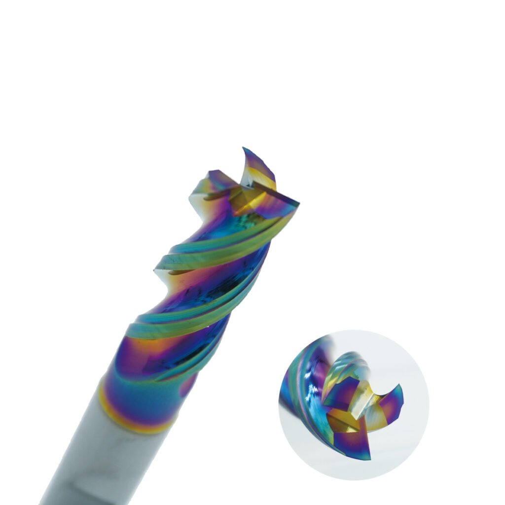
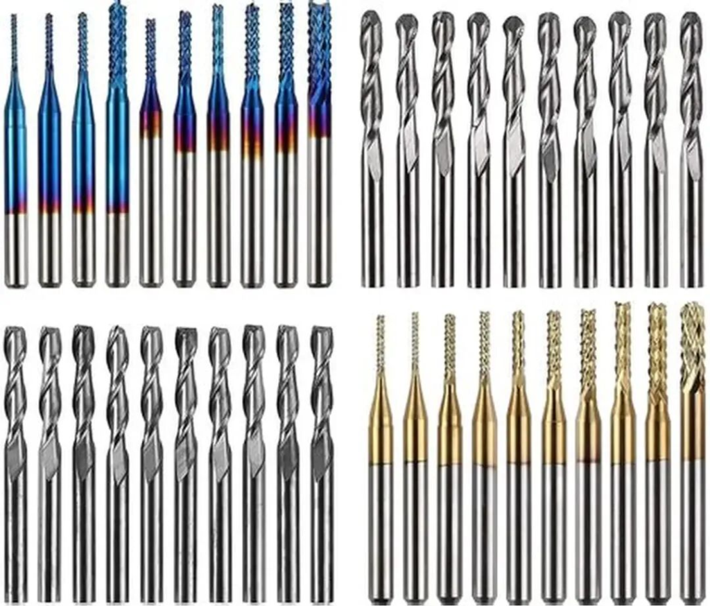
Coatings should be evaluated against the workpiece rather than treated as a universal upgrade. A coating can reduce wear or resin adhesion in a suitable application, but geometry, edge preparation, runout, and chip evacuation usually determine the result before color or marketing name does.
Match flute direction to sheet construction
Plywood and veneered panels fail at their outer layers. If the top veneer is visible, a downcut or compression tool usually gives better control than a general-purpose upcut bit. For a through-cut with a compression tool, the programmed depth must put the upward-cutting tip below the bottom face while the downcut portion works at the top. A shallow first pass that leaves the upcut section inside the top veneer can cause exactly the tear-out the operator expected the compression tool to prevent.
MDF machines uniformly but is abrasive and produces fine dust. A sharp carbide tool, effective extraction, and a chip load that forms real chips rather than powder help control heat. Long production runs may justify diamond tooling.
Solid wood adds grain direction and density variation. Climb cutting often leaves a smoother edge on a rigid CNC router, but knots, figured grain, thin walls, and weak hold-down can change the safest strategy. A light finishing allowance can separate the heavy material-removal pass from the final edge-quality pass.
Softwood can compress and fuzz instead of cutting cleanly when the edge is dull or the chip is too thin. Increasing feed within the toolmaker’s limits, lowering RPM, or changing to a sharper geometry can reduce rubbing. The correct adjustment depends on spindle load, sound, chip form, and edge quality, so change one variable at a time.
Size the bit for stiffness and access
Larger diameters remove material faster and resist deflection. Smaller tools reach fine details and narrow internal corners, but they carry less load and have less flute space for chips. Use the largest diameter that can reproduce the smallest required feature and clear the toolpath.
Cutting length is not a free benefit. A long cutting edge and long stick-out reduce stiffness. Select a tool with enough reach for the programmed depth, then keep the projection from the collet as short as the job allows. Do not clamp on the flute, transition, or any area not intended as the shank. Leave a small gap between the shank end and the bottom of the collet so tightening does not force the tool against the internal seat.
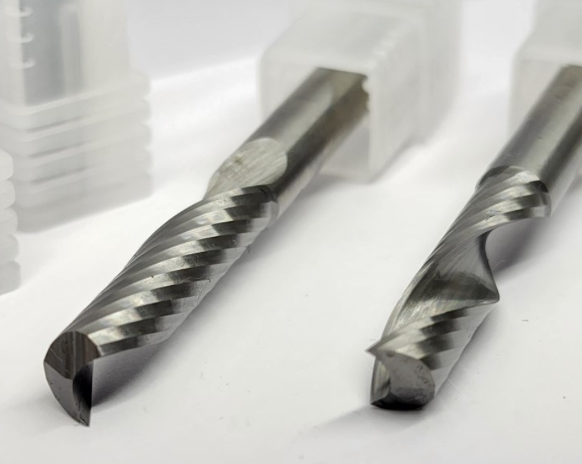
Two flutes are a common starting point in wood because they leave more space for chips at high feed rates. A single flute can help a machine with limited feed capability maintain adequate chip thickness. Three or more flutes can improve finish in a stable process, but the feed rate must rise to preserve the same chip load, and the smaller gullets have less room for debris.
Set feeds and speeds from chip load
Chip load is the nominal thickness removed by each cutting edge:
Chip load = feed rate ÷ spindle speed ÷ number of flutes
The rearranged formula is more useful during setup:
Feed rate = chip load × spindle speed × number of flutes
For example, a two-flute bit at 18,000 rpm and a target chip load of 0.008 inch per tooth gives a calculated feed of 288 inches per minute. That number is an illustration, not a recommendation for every wood species or bit. Tool diameter, flute geometry, workpiece construction, spindle power, hold-down, depth of cut, machine acceleration, and the manufacturer’s test data all matter.
Start with the bit maker’s range for the exact series and material. If a machine cannot reach the calculated feed, reducing RPM may preserve chip thickness better than letting the cutter rub at full speed. Listen for chatter or spindle bogging, inspect both faces, and look at the waste. Fine dust, darkened edges, resin buildup, or a hot tool can indicate rubbing, poor extraction, or recutting. Oversized chips, vibration, deflection marks, or a rough wall can indicate excessive load.
Plan depth of cut and toolpath engagement
There is no universal rule that the depth per pass must equal one tool diameter. A short, rigid bit on a powerful industrial router can take a very different cut from a long 3 mm tool on a desktop machine. Begin with the toolmaker’s data, then account for slot width, tool stick-out, material density, and hold-down.
Full-width slotting is demanding because the tool cuts on both sides and chips have fewer escape paths. Pocketing with an adaptive or offset strategy can reduce engagement. Ramps and helical entries are often kinder to the tool than a straight plunge, particularly when the bit does not have a center-cutting geometry designed for plunging.
Separate roughing and finishing when edge tolerance matters. Leave a small, consistent radial allowance during roughing, then make a full-depth finishing pass with low radial engagement. This reduces the effect of tool deflection and gives the final edge a more consistent cutting condition.
Climb cutting moves the cutter edge in the same direction as feed at the contact point. On a rigid CNC machine with controlled backlash, it often produces a cleaner wall and lower rubbing. Conventional cutting may be useful when the part or grain reacts poorly to climb cutting, or when a light cleanup pass benefits from the opposite engagement. Test on the real stock rather than treating either direction as an absolute rule.
Install the tool and prove the setup
Clean the collet, collet nut, spindle taper, and tool shank before installation. Resin or dust trapped in the assembly can increase runout and reduce grip. Replace a worn collet rather than compensating with more tightening torque. Use the spindle manufacturer’s torque specification and the correct wrench arrangement.
Set Z zero with the same method used in the production program. If the CAM file references the spoilboard but the operator zeros on the material top, the entire depth strategy will be wrong. This matters greatly with compression bits because the flute transition must land in the intended part of the sheet.
Run a short test in offcut from the actual batch. Confirm the fit of slots and dados, top and bottom edge quality, dust extraction, part hold-down, and the remaining onion skin or tab thickness. An air cut above the workpiece is appropriate when checking a new postprocessor, fixture, or coordinate setup.
Diagnose common cut problems
Problem | Likely causes | Practical checks and corrections |
Burned edge or resin on the bit | Chip load too low, dull edge, poor extraction, repeated chip recutting | Increase feed or reduce RPM within the approved range, clean the tool, inspect sharpness, and improve chip removal |
Tear-out on the top face | Upcut geometry, dull edge, weak surface veneer, wrong compression engagement | Try downcut or compression geometry, verify first-pass depth, add a light finishing pass, and support fragile veneer |
Tear-out on the bottom face | Downcut geometry or insufficient support below the sheet | Use upcut or compression geometry, maintain a sound spoilboard, and ensure the tool exits into suitable support |
Fuzzy solid wood edge | Dull tool, unfavorable grain direction, low chip thickness, flexible tool setup | Shorten stick-out, use a sharper shear geometry, test the opposite cut direction, and add a finishing pass |
Chatter marks | Weak hold-down, excessive stick-out, high engagement, runout, loose machine components | Improve fixturing, shorten the tool, reduce engagement, inspect collet and bearings, and check machine rigidity |
Bit breaks | Excessive load, packed chips, collision, too-small diameter, poor entry move | Review feed and depth together, clear chips, use a ramp or helix, enlarge the tool where geometry permits, and verify coordinates |
Parts shift during through-cut | Low vacuum area, small nested parts, aggressive upcut force, missing tabs or onion skin | Improve gasketing and spoilboard condition, change cut order, add tabs or onion skin, and consider downcut or compression geometry |
Dados fit incorrectly | Tool diameter or runout differs from CAM assumption, sheet thickness varies, tool deflection | Measure the cut, verify actual tool diameter and runout, sample sheet thickness, and use a calibrated finishing allowance |
Maintain cutters and toolholding as one system
Clean resin before it hardens, using a product suitable for the tool and coating. Avoid wire brushing or careless scraping that can damage a sharp edge. Inspect under good light for chips, cracks, wear flats, and discoloration. A tool that needs more feed override or produces a steadily worse edge has already begun to affect production cost.
Complex carbide profiles and precision spiral tools should be serviced by a qualified sharpening provider. Regrinding changes diameter, so CAM tool data and offsets must be updated before the tool returns to production. A sharpened compression bit may also have a changed transition or cutting length that affects the programmed first pass.
Store each cutter so edges cannot strike other tools. Label reconditioned tools with their measured diameter and service status. Keep collets on a preventive replacement schedule based on use and condition. Router-bit life is difficult to compare if the shop does not record material, runtime or linear distance, settings, failure mode, and edge result.
Build a reliable purchasing specification
Tool buyers need more than a diameter and shank size. A useful request for quotation states the workpiece material and facing, operation, cutting depth, spindle interface, available RPM and power, feed capability, required edge quality, expected monthly volume, and whether the cut is blind or through. For compression tooling, specify sheet thickness and the permissible first-pass depth.
Ask the supplier for the recommended chip-load range, maximum RPM, resharpening limits, dimensional tolerances, and suitable collet engagement. For high-volume MDF or laminated panel work, compare cost per finished part rather than purchase price alone. A more expensive tool can be the lower-cost option when it reduces edge rework and unplanned changes.
Final selection checklist
Decision | Question to answer before programming |
Material | Is the stock solid wood, plywood, veneered panel, MDF, laminate, or plastic sheet |
Visible faces | Does the top, bottom, or both faces require a clean edge |
Operation | Is the tool slotting, pocketing, profiling, engraving, trimming, surfacing, or finishing |
Geometry | Should chip flow move up, down, or toward the sheet center |
Size | What is the largest rigid diameter that still reaches the smallest feature |
Reach | Can the required depth be reached with minimal stick-out and full shank engagement |
Parameters | What starting chip load and limits does the exact tool manufacturer publish |
Hold-down | Can vacuum, clamps, tabs, or onion skin resist the axial force and cutting load |
Verification | What offcut test will confirm fit, edge quality, spindle load, and chip evacuation |
Maintenance | How will the shop clean, inspect, measure, store, and retire the tool |

Conclusion
The best CNC router bit is the one whose geometry fits the operation, visible face, machine, and hold-down method. Upcut, downcut, and compression spirals solve different chip-flow and edge-quality problems. Diameter, cutting length, flute count, and carbide grade then determine how much load the tool can carry.
Use the manufacturer’s cutting data to establish the first test, not the final production setting. A controlled test cut and a written process record turn router-bit selection from trial and error into a repeatable shop method. HNCarbide can support OEM and production buyers who need solid carbide router tooling matched to their workpiece, spindle, and output requirements.