How Cutting Tool Material Properties Shape Tool Design
Table of Contents
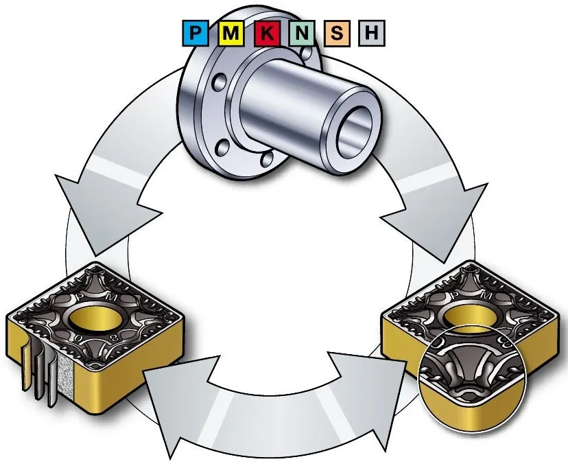
A cutting tool can have an excellent carbide grade and still fail quickly if its geometry asks that grade to do the wrong job. A razor-sharp edge may cut aluminum cleanly but chip as soon as it meets a scale-covered forging. A thick, heavily honed edge may survive an interrupted cut, yet create excessive force and heat in a light finishing pass.
This is why cutting material and tool geometry cannot be selected in separate steps. Hardness, wear resistance, toughness, hot hardness, thermal conductivity, and chemical stability set the limits within which the designer can choose rake angle, clearance, edge preparation, flute volume, nose radius, and coolant strategy. The tool only works when these choices support one another.
The material property trade-off behind every cutting edge
Cutting materials are expected to retain a hard edge while carrying high compressive loads, sliding against a hot chip, and surviving vibration or impact. No single property covers all of that. Improving one characteristic often narrows another part of the application window.
In cemented carbide, for example, a harder and more wear-resistant grade can support higher cutting speed and resist abrasive flank wear. It is usually less forgiving of runout, interrupted engagement, or an unstable setup. A tougher grade tolerates those mechanical shocks better, but it may deform or wear faster when heat and sliding distance dominate.
The practical question is not “Which material is best?” It is “Which failure mode must this tool resist first?” Once that is clear, geometry can be used to protect the selected material without making the cutting action unnecessarily heavy.
Material property | What it helps the tool resist | Design response it often permits or requires | Risk when pushed too far |
Hardness | Edge indentation and abrasive attack | Smaller edge radius, tighter dimensional retention, higher permissible speed | Brittle microchipping if support is inadequate |
Wear resistance | Progressive flank and crater wear | Longer engagement, higher production volume, stable finishing geometry | Sudden fracture may replace gradual wear |
Toughness | Impact, chatter, interrupted cuts, entry and exit shock | Stronger edge, larger wedge angle, more robust flute core | Higher friction or faster wear at temperature |
Hot hardness | Softening and plastic deformation at cutting temperature | Higher cutting speed and sustained contact | Thermal shock can still crack a hard material |
Thermal conductivity | Heat movement away from the edge | Influences coolant delivery and edge temperature control | Rapid thermal cycling may create cracks |
Chemical stability | Diffusion, adhesion, and reaction with the workpiece | Coating and rake-face finish can be optimized for the alloy | A chemically incompatible tool can wear despite adequate hardness |
Hardness sets the edge-retention limit
Hardness matters because the edge is continuously pressed and rubbed by the workpiece and chip. A tool material that is too soft for the cutting temperature will round over, develop a wear land, or plastically deform. Dimensional accuracy then drifts even if the tool has not visibly broken.
Higher hardness gives a designer more freedom to maintain a small edge radius and a precise profile. That is useful in finishing tools, micro-tools, reamers, and form cutters, where a few micrometers of edge loss can change the part. It also supports the high contact pressure at a sharp cutting edge.
Hardness alone does not make an edge reliable. A very hard substrate with a thin wedge, large positive rake, and insufficient support can chip under feed load. Designers compensate by increasing the wedge angle, adding a controlled hone or chamfer, and strengthening the core behind the flute. The goal is to keep the edge sharp enough to cut while reducing the peak tensile stress that starts a crack.
This distinction is important for buyers comparing nominally similar tools. Two end mills may use “micrograin carbide,” yet their edge preparation and core diameter can make one a finishing tool and the other a roughing tool. Grade labels do not describe the whole design.
Wear resistance determines whether failure is gradual and predictable
Wear resistance governs how quickly the tool loses material from the flank and rake face. In stable production, gradual flank wear is preferable to random edge fracture because it can be measured and built into a tool-change interval.
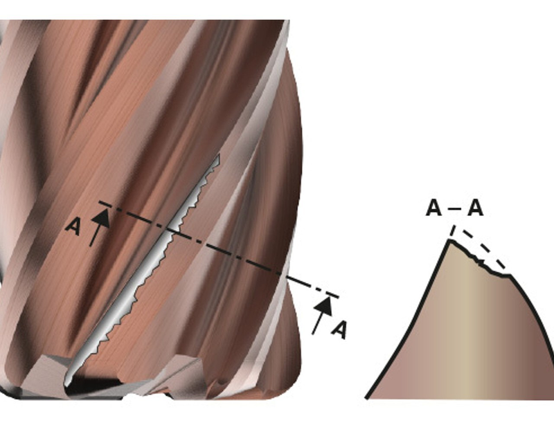
For abrasive cast iron, glass-filled composites, hardened surfaces, or scale, designers favor substrates and coatings that resist abrasion. Geometry still matters. Adequate clearance prevents the flank from rubbing, while a polished rake face reduces chip friction and built-up material. If clearance is too large, however, the wedge becomes weak. If it is too small, rubbing generates more heat and makes a wear-resistant grade fail for the wrong reason.
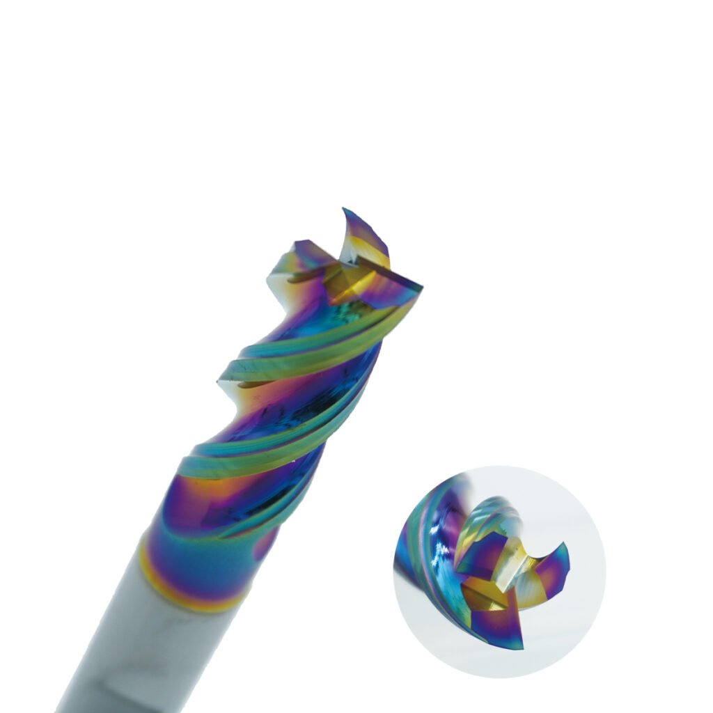
Coatings add another layer to the design. A hard coating can delay abrasive and crater wear, but its performance depends on substrate support and edge preparation. An extremely sharp edge may not carry a thick coating uniformly. A heavily honed edge accepts the coating more robustly but increases ploughing at low feed per tooth. The hone therefore has to match both coating thickness and the minimum chip thickness of the operation.
Wear resistance also affects indexing economics. A stable insert that develops a repeatable wear land can be indexed at a planned limit. A brittle grade that survives longer on average but occasionally breaks may cost more once scrap, toolholder damage, and unattended-machine risk are included.
Toughness decides how much interruption the tool can survive
Toughness is the ability to absorb energy before cracking. It becomes critical in milling, interrupted turning, scale removal, cross-hole drilling, and any setup with limited rigidity. Entry and exit impose repeated mechanical shocks; runout then concentrates load on one tooth or insert.
A tougher tool material allows the designer to handle these conditions with a robust edge and a strong body. Common responses include a larger wedge angle, a larger nose radius, a negative land, a reinforced flute core, or fewer flutes to preserve chip space and cross-sectional strength. These features lower local stress, but they can raise cutting force. The machine, fixture, and workpiece must be able to carry that force without deflecting.
The statement that “more toughness is always safer” is misleading. A very tough but less wear-resistant grade can lose its geometry rapidly in a long, stable cut. It may also encourage a blunt edge design that rubs in low-feed finishing. Toughness should cover the real shock load, not compensate for avoidable runout, poor fixturing, or incorrect engagement.
Operating condition | Likely design priority | Typical geometry direction | Material direction |
Continuous finishing on a rigid machine | Edge retention and low force | Positive rake, small edge hone, precise clearance | Harder, more wear-resistant grade |
Interrupted turning or scale | Edge security | Strong wedge, controlled chamfer, larger nose radius where stable | Tougher substrate and coating system |
High-speed dry or near-dry cutting | Thermal stability | Low-friction rake face, heat-managing edge preparation | High hot hardness and oxidation-resistant coating |
Deep-slot milling | Chip evacuation and core strength | Fewer flutes, larger gullets, balanced core | Tough grade with adequate wear resistance |
Micro-machining | Edge integrity and low minimum chip thickness | Very small edge radius, polished flutes, minimal runout | Fine-grain material with high hardness and reliable strength |
Hot hardness and thermal stability shape speed, cooling, and edge mass
Cutting temperature can soften the binder phase of carbide and reduce the load-bearing capacity of the edge. Once the edge begins to deform, the contact area grows, friction rises, and failure accelerates. A tool that appears sufficiently hard at room temperature may therefore be unsuitable at production speed.
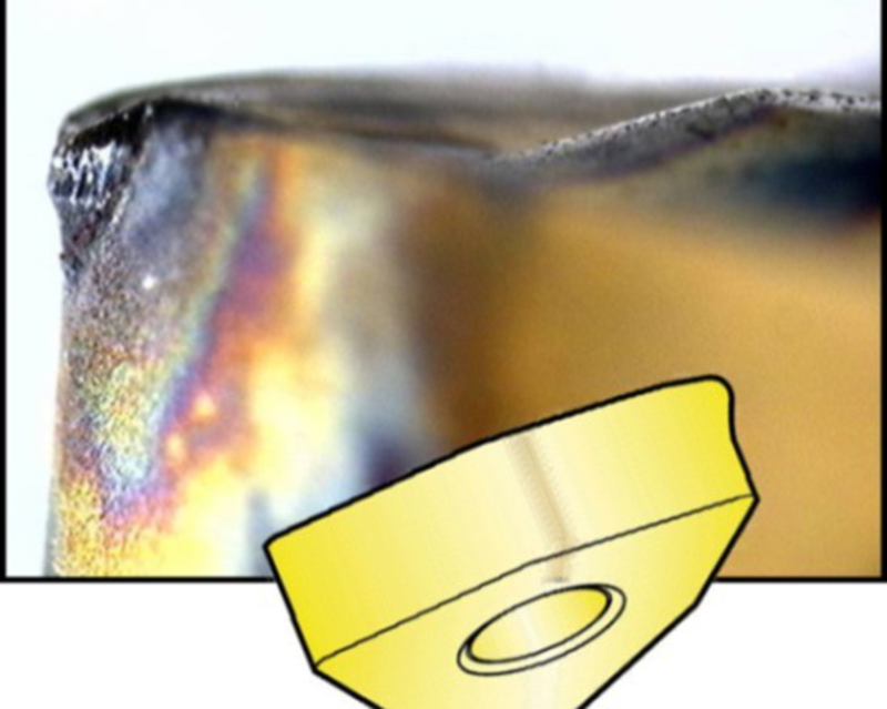
Materials with high hot hardness give designers more room to use higher cutting speed or maintain contact for longer. Ceramic and CBN tools exploit this in suitable hard-turning and cast-iron applications. Their lower fracture tolerance, however, calls for stable engagement, strong edge support, and carefully controlled entry. The geometry that works for a tough carbide insert is not automatically suitable for a ceramic one.
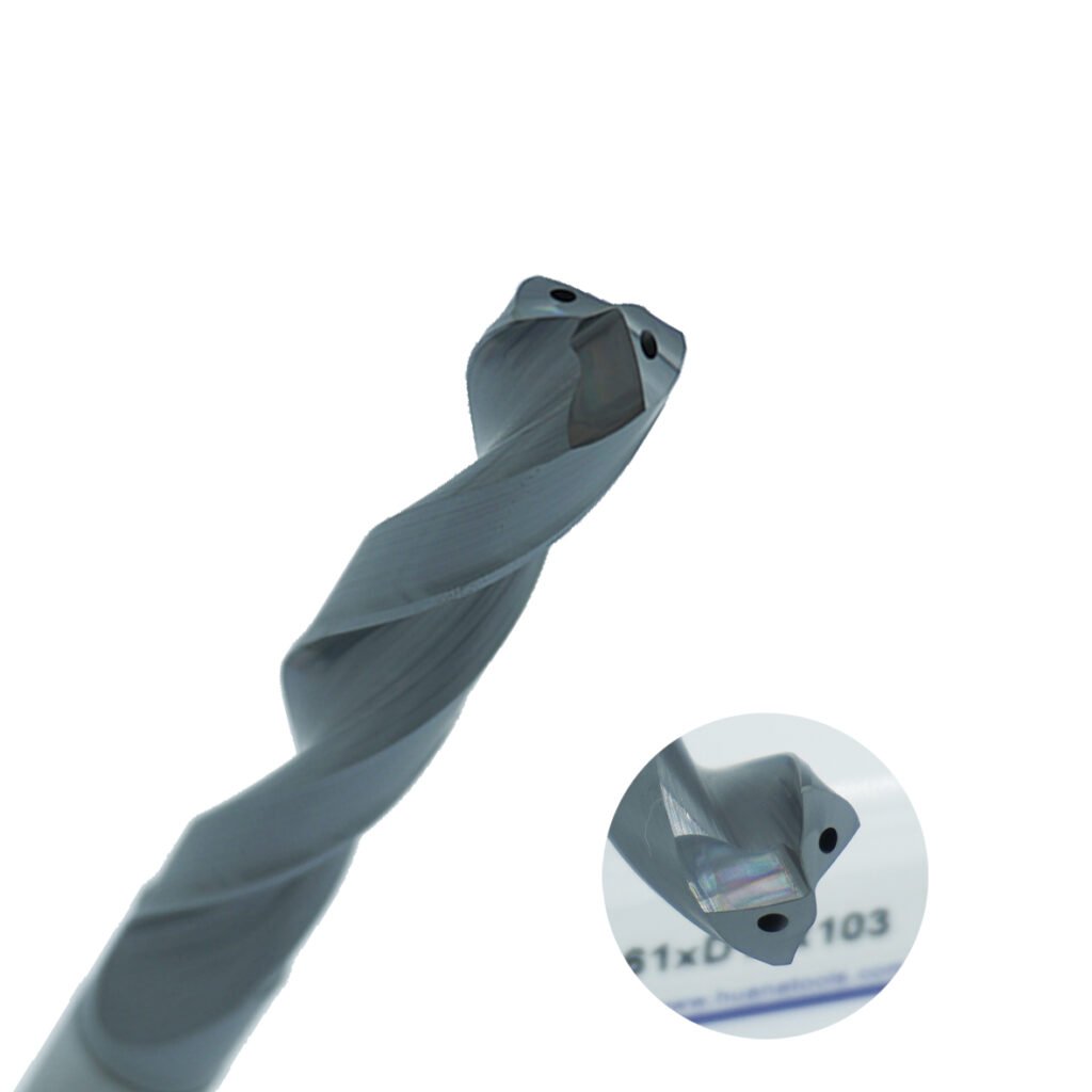
Thermal conductivity changes where the heat goes. In titanium and nickel-based alloys, the workpiece conducts heat poorly, so more heat remains near the cutting edge. A positive rake and sharp edge can reduce deformation and heat generation, while coolant channels must aim fluid at the actual contact zone. On a solid carbide drill, internal coolant supply also supports chip evacuation; blocked chips create friction that no substrate grade can fix.
Cooling strategy must account for thermal cycling. Intermittent coolant on a hot edge can be worse than a stable dry process because repeated heating and quenching create comb-like cracks.
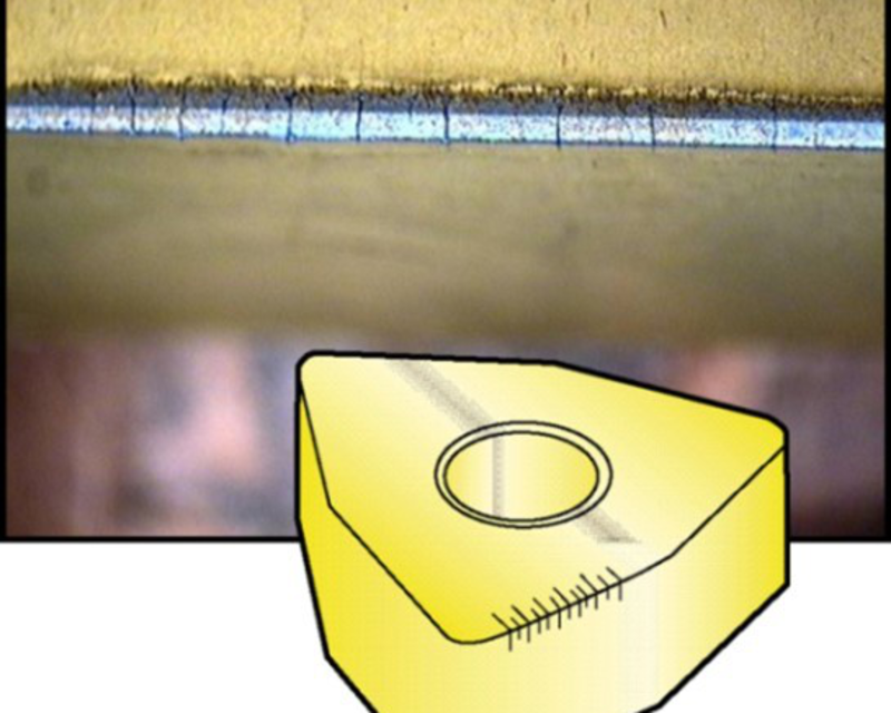
The designer can reduce this risk through a tougher substrate, a more heat-tolerant coating, a free-cutting geometry, and coolant delivery that is either consistent or deliberately avoided where dry cutting is recommended. The operator must then preserve that thermal strategy in production. Random changes in coolant flow can invalidate the tool design.
Geometry translates material capability into cutting behavior
Material properties define what an edge can survive; geometry decides the loads it will see. Several design variables are especially sensitive to the chosen tool material.
Rake angle and wedge angle
A positive rake lowers cutting force and temperature, which is valuable for sticky alloys, thin walls, and low-power machines. The trade-off is a smaller wedge behind the edge. Tougher substrates tolerate this better. Brittle cutting materials often need a stronger wedge, neutral or negative rake, and a stable machine.
Edge sharpness, hone, and chamfer
An unprepared sharp edge reduces ploughing, but its microscopic peaks are vulnerable. Honing removes those weak peaks and spreads load over a larger area. A chamfer adds still more support for interrupted or high-feed cuts. The preparation must remain proportional to feed: if the edge radius approaches the uncut chip thickness, the tool rubs instead of shearing cleanly.
Clearance angle
More clearance reduces flank contact and heat. It also removes support from the cutting edge. Hard, brittle grades may need conservative clearance, while sharp tools for aluminum and other low-force applications can use more relief when the substrate and body remain strong enough.
Flute count, gullet size, and core diameter
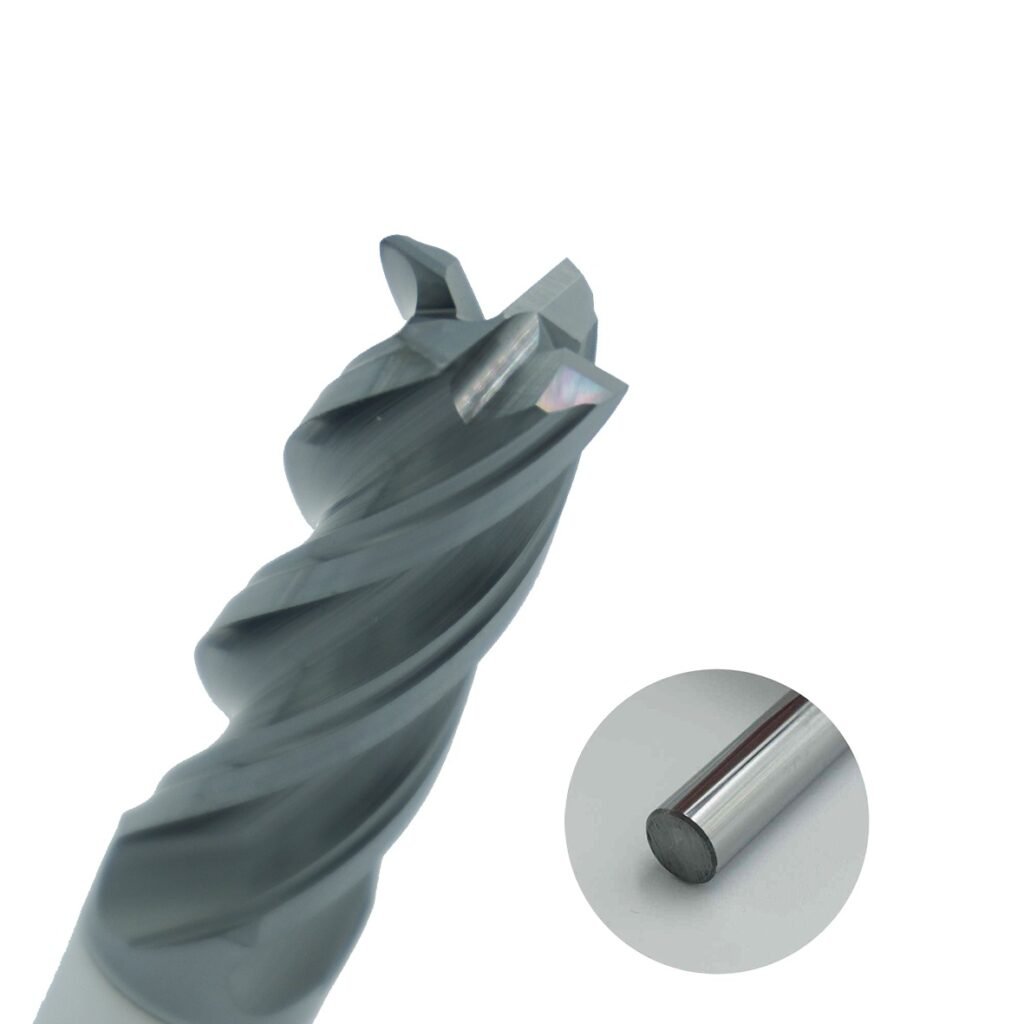
Adding flutes increases the number of cutting edges and can improve productivity in materials that form small chips. It reduces gullet space and may weaken the core if the outside diameter is fixed. A tough substrate helps a slender geometry survive, but chip packing will still break the tool. Long-chipping materials often need fewer flutes and more evacuation space even when a higher flute count looks attractive on paper.
Match the design to the dominant failure mode
When a tool fails, changing to a harder grade is only one possible response. The failure surface often points to a better combination of material and geometry.
Observed problem | What it usually suggests | Material change to consider | Geometry or process change to consider |
Fast, even flank wear | Abrasion, excessive speed, or insufficient hot hardness | More wear-resistant grade or suitable coating | Check clearance, reduce speed, improve coolant delivery |
Small chips along the edge | Impact, vibration, or insufficient edge support | Tougher grade | Larger hone/chamfer, stronger wedge, reduce runout and overhang |
Plastic deformation | Thermal and mechanical overload | Higher hot-hardness grade | Reduce speed/load, increase edge support, improve cooling consistency |
Comb cracks | Repeated thermal cycling | Tougher thermal-shock-resistant grade | Stabilize coolant, reduce temperature swing, use freer-cutting geometry |
Built-up edge | Adhesion and excessive rubbing | Chemically suitable coating or polished substrate | Sharper rake face, adequate feed, correct speed and coolant |
Tool breakage in a deep slot | Chip packing or core overload | Tougher grade only after evacuation is corrected | Fewer flutes, larger gullets, shorter overhang, lower engagement |
This approach prevents a common troubleshooting loop: selecting an increasingly hard grade while leaving the stress concentration, chip packing, or thermal shock unchanged. The replacement then fails differently, but not necessarily later.
A practical selection sequence for engineers and buyers
Start with the operation rather than the catalog grade. Identify whether the cut is continuous or interrupted, the rigidity of the machine and fixture, chip length, workpiece abrasiveness, cutting temperature, and required tolerance. Next, name the most costly failure mode. Tool wear, random fracture, burrs, poor finish, and dimensional drift lead to different design priorities.
Then review the complete specification:
- Substrate:grain size, binder balance, hardness, transverse rupture strength or supplier toughness class.
- Coating:deposition method, thickness, thermal capability, friction behavior, and compatibility with the substrate and workpiece.
- Edge preparation:hone size, chamfer width and angle, edge consistency, and whether the preparation matches feed per tooth.
- Macro geometry:rake, clearance, helix, flute count, core diameter, chipbreaker, nose radius, and coolant channels.
- Process assumptions:speed, feed, engagement, coolant mode, runout, holder, and allowable overhang.
For a production trial, record wear mode and variance rather than tool life alone. Ten tools averaging 60 minutes with a narrow spread can be more valuable than a grade averaging 70 minutes with occasional failure at 25 minutes. Stable wear makes tool-change planning, lights-out machining, and cost-per-part estimates more credible.

The design is a balance, not a material ranking
Material properties have a major influence on cutting tool design because they determine how thin, sharp, hot, and heavily loaded an edge can be before it wears or fractures. Geometry then converts those limits into cutting performance. Hardness without support chips; toughness without wear resistance loses size; hot hardness without thermal-shock control cracks.
For custom carbide tools, HNCarbide can review the workpiece, engagement, machine conditions, and target failure mode before recommending a substrate, coating, and geometry combination. The useful specification is the one that explains how those elements work together in the actual cut.