Milling Machining: From Face Milling to High-Speed Machining
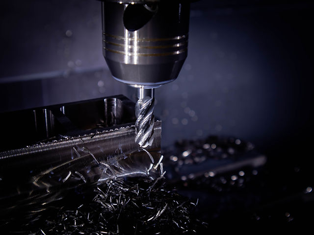
Milling is the workhorse process for prismatic parts. Engine blocks, gearbox housings, mold cavities, aircraft structures and precision fixtures all depend on it because one CNC machine can create flat faces, pockets, shoulders, slots and complex 3D surfaces in a controlled setup.
The process is deceptively familiar: the cutter rotates while the part, tool, or both move along a programmed path. What makes it demanding is that milling is intermittent, multi-edge cutting. Each tooth repeatedly enters and leaves the material. Chip thickness, cutting force and heat therefore change throughout every revolution. A productive process depends on matching the cutter, engagement, toolpath and holding method—not simply raising spindle speed.
This guide gives production teams and tooling buyers a practical framework for selecting milling tools, choosing between climb and conventional milling, setting core parameters and applying high-speed machining safely.
How milling motion and parameters work
The cutting speed at the outside diameter of a cutter is determined by cutter diameter and spindle speed. Feed is normally programmed as feed rate in mm/min, but its more useful planning value is feed per tooth (fz):
Feed rate (mm/min) = fz (mm/tooth) × number of teeth × spindle speed (rpm)
Two engagement values must be kept distinct. Axial depth of cut (ap) is measured along the tool axis; radial width of cut (ae) is measured perpendicular to it. In a pocket, a 12 mm end mill taking 12 mm axially but only 1.5 mm radially is experiencing a very different load from the same tool fully slotting at 12 mm depth.
The interrupted cut gives each tooth a brief cooling interval, but it also introduces impact. That is why secure workholding, low runout and a tool with appropriate edge preparation matter as much as the numbers entered in the control.
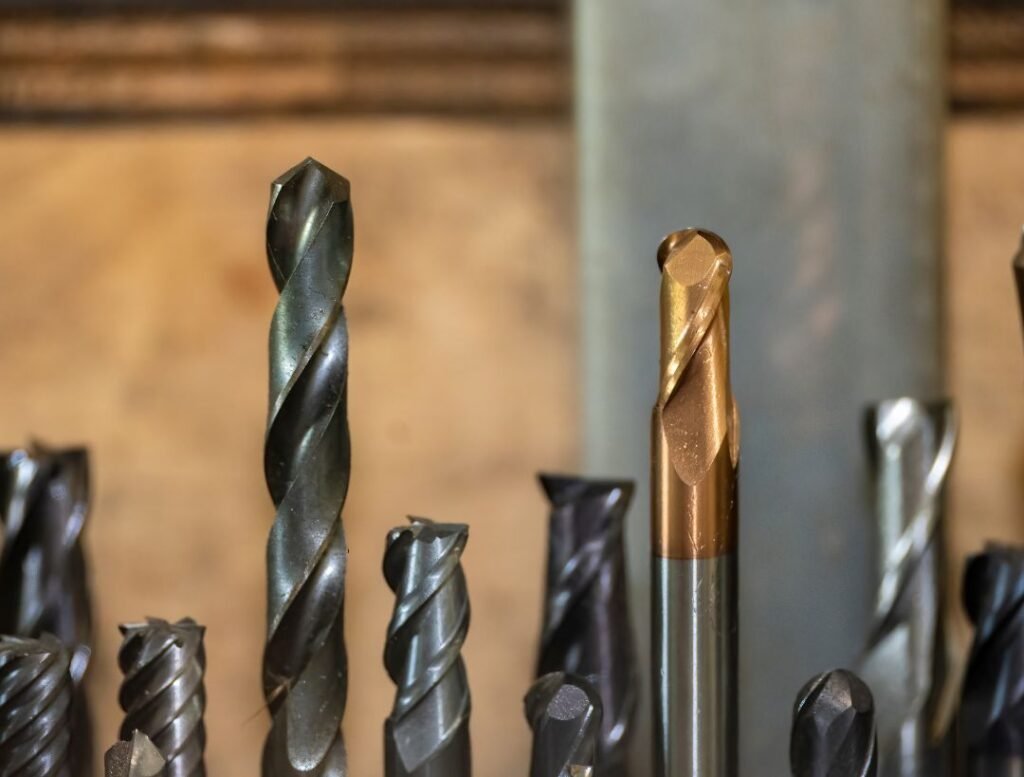
Cutter families and where they earn their place
Cutter type | Best-fit work | Selection note |
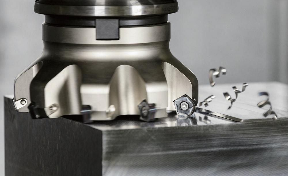
Indexable face mill | Large datum faces and broad planar areas | High metal-removal rate; use wiper inserts where surface finish is critical. |
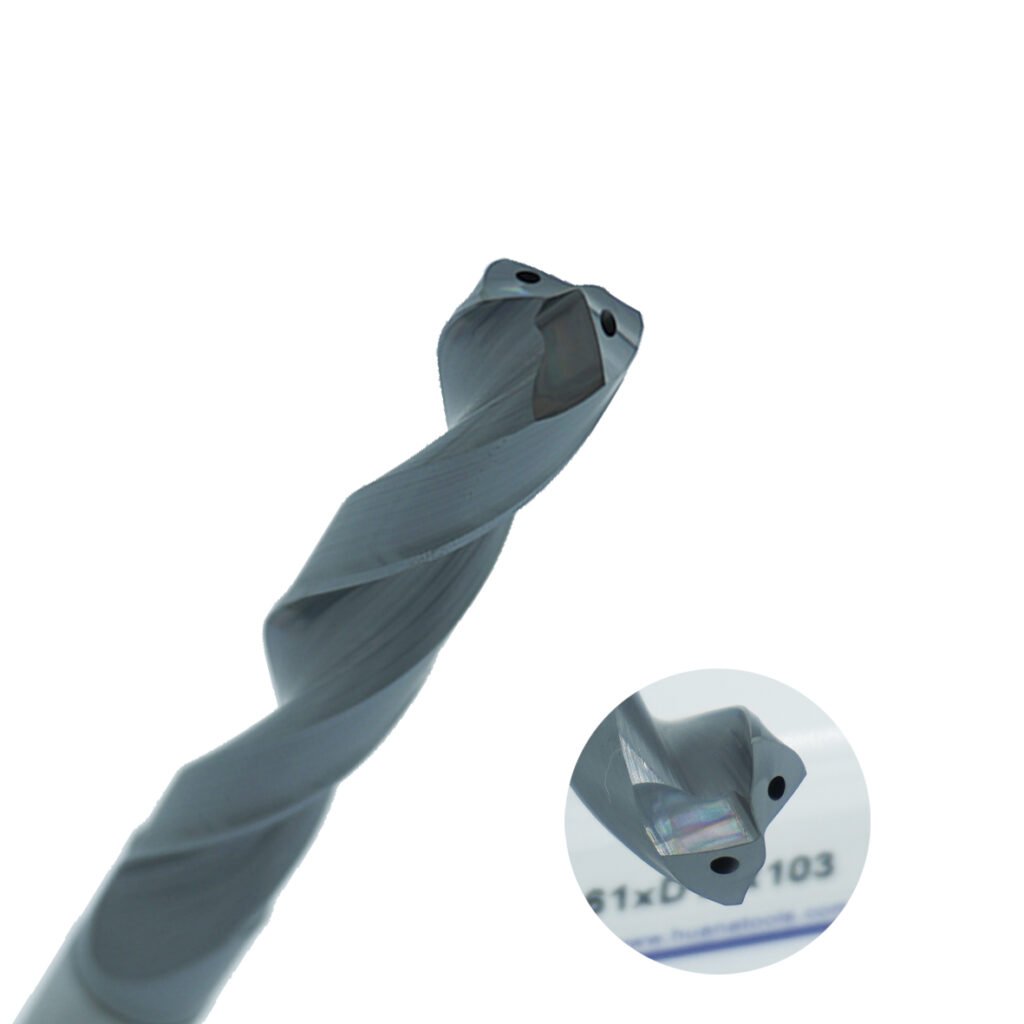
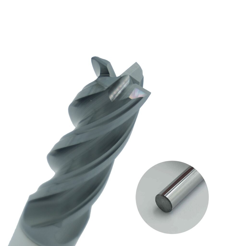
Solid-carbide square end mill | Profiles, shoulders, pockets and general milling | Two flutes favor chip space in aluminum; four or more flutes suit stable steel finishing. |
Corner-radius end mill | Cavity roughing and semi-finishing | Stronger than a sharp-corner tool and less prone to corner chipping. |
Ball-nose end mill | 3D finishing, blends and fillets | Avoid cutting exactly at the tool center, where effective speed approaches zero. |
Slot, T-slot or keyseat cutter | Dedicated grooves and undercuts | Plan chip evacuation before increasing depth. |
Thread mill | Large, difficult or variable-diameter internal threads | One tool can cover both right- and left-hand threads with interpolation. |
Face, peripheral and slot milling
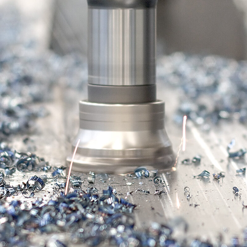
Face milling uses the cutter’s end region to generate a flat surface. Multiple inserts can share the load, making it the usual first choice for large faces. Insert height consistency, cutter overhang and machine rigidity all influence flatness and finish.
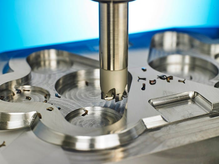
Peripheral milling cuts mainly with the cylindrical outside of an end mill. It is the normal method for profiles, walls and narrow surfaces. Full-width slots are the most demanding version because both sides of the cutter are engaged and chips have fewer routes to escape. Use reduced radial engagement or a trochoidal/adaptive path when the machine and CAM system permit it.
For deep or wide grooves, split the operation into sensible axial or radial stages. A T-slot is typically made by first milling a straight access slot, then opening the lower feature with a T-slot cutter. Asking the form cutter to remove all material at once is a common source of chatter and broken teeth.
Climb milling versus conventional milling
In climb milling, cutter rotation and feed direction coincide at the point of cut. The tooth starts at maximum chip thickness and exits at zero. On a modern CNC machine with preloaded ballscrews, climb milling generally produces a better finish, less rubbing and longer predictable tool life.
Conventional milling starts at near-zero chip thickness and builds up. It can be useful when removing a hard cast skin, scale or an inconsistent outer layer, because it avoids driving the cutting edge directly into that surface at full thickness. It is also the safer choice on older equipment with backlash that cannot be controlled.
Condition | Usually preferred approach | Why |
Stable CNC machine; finished steel or aluminum surface | Climb milling | Cleaner cut and less edge rubbing. |
Cast skin, scale or interrupted outer layer | Conventional milling for the first pass | More forgiving initial edge engagement. |
Thin wall or flexible setup | Climb milling with reduced radial engagement | Lowers side load and deflection risk. |
Machine with significant backlash | Conventional milling or machine repair | Climb milling may pull the table into the cut. |
A reliable sequence for pockets and complex surfaces
Pocket machining rewards process separation. Rough with a rigid, corner-radius end mill and a constant-engagement toolpath; leave a consistent allowance on walls and floors. Semi-finish to stabilize stock and expose any distortion. Finish with a tool geometry that matches the required corner radius and surface tolerance.
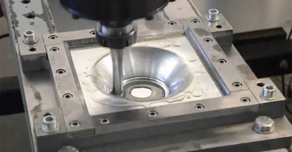
For 3D mold surfaces, a ball-nose tool is a finishing tool rather than an automatic roughing choice. Its center has almost no cutting speed. A flat-bottom or bull-nose tool is usually more efficient for roughing, while a ball nose follows the final surface with a calculated stepover. In five-axis work, tilting the tool moves the contact point away from the center and can improve both finish and tool life.
Starting values: treat them as a controlled trial, not a promise
Published cutting data is a starting window; machine condition, toolholder, coolant strategy, stock allowance and material batch can all change the result. The ranges below are deliberately broad and should be verified with the cutter supplier’s data and a supervised first article.
Application | Typical tool | Indicative cutting-speed window | Practical focus |
Carbon steel face milling | Coated indexable face mill | 150–250 m/min | Check insert seating and wiper height before chasing finish. |
Cast iron face milling | Coated indexable face mill | 150–200 m/min | Control abrasive wear and avoid unstable scale engagement. |
Aluminum milling | Polished carbide or sharp indexable tool | 300–600 m/min | Prioritize chip evacuation and prevent built-up edge. |
General steel end milling | Solid-carbide end mill | 60–120 m/min | Use a toolholder with low runout; protect the smallest flute. |
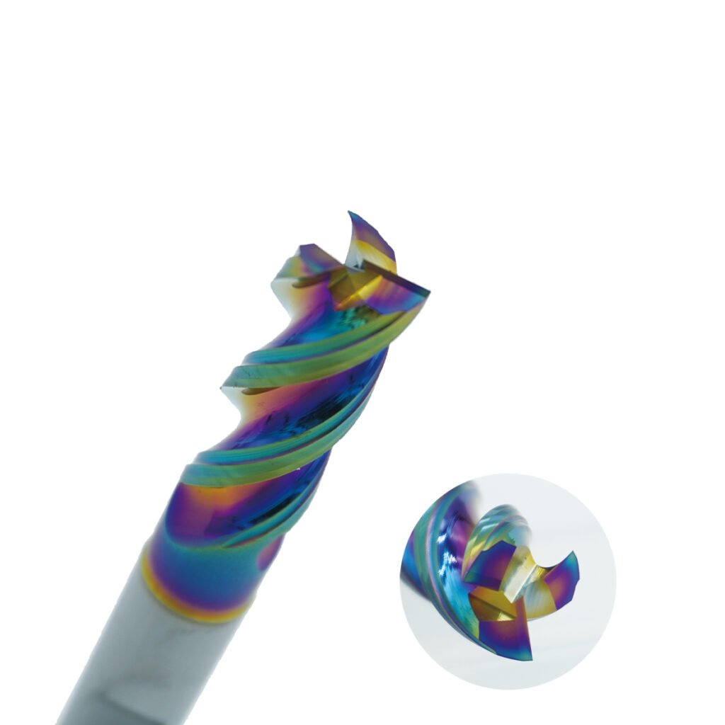
Hardened-tool-steel finishing | Fine-grain coated carbide | 80–150 m/min | Keep toolpaths smooth; use light radial engagement. |
For a stable roughing cut, many shops aim for feed per tooth in the approximate 0.10–0.30 mm/tooth range; finishing often starts nearer 0.05–0.15 mm/tooth. Those numbers are not transferable to every diameter or material. Small ball mills, for example, demand much lighter feed because the edge is less robust.
When a setup begins to vibrate, reduce radial engagement first. This often drops radial cutting force while preserving a useful axial depth. Then review tool overhang, workholding, spindle condition and CAM transitions before simply slowing everything down.
Solving the defects that cost the most time
Symptom | Likely causes | First corrective actions |
Poor surface finish | Excessive fz, tool runout, worn edge, chip recutting | Verify holder and tool runout; renew the edge; improve air/coolant and chip escape. |
Size variation or tapered wall | Deflection, incorrect offset, thermal movement | Separate rough and finish passes; shorten projection; re-measure and adjust compensation. |
Scallops or uncut stock on 3D work | Stepover too large, wrong tool radius, tool deflection | Recalculate stepover; use the correct corner radius; reduce side load. |
Chatter | Long overhang, weak fixture, unsuitable tooth pitch or engagement | Shorten the assembly; strengthen clamping; change engagement before reducing all parameters. |
Flatness error on a face | Uneven insert height, part distortion, thermal growth | Inspect seats and inserts; support the workpiece; keep the finishing pass thermally consistent. |
High-speed machining: a system, not a spindle number
High-speed milling is often described as running above 10,000 rpm, but the useful definition is broader: a coordinated high-speed process with low, controlled radial engagement, a relatively deep axial cut where tool geometry allows it, high feed rate and smooth motion. In hardened-tool-steel finishing, radial engagement may be only a fraction of a millimeter.
The benefits can be substantial. Lower and more stable cutting forces support thin features. A larger portion of heat leaves with the chip. Hardened mold components can sometimes move directly from machining to light finishing, reducing EDM and polishing work. None of that follows from rpm alone.
High-speed work needs a balanced tool assembly, a high-quality holder, controlled runout—often targeted below 0.005 mm for small finishing tools—and CAM paths without abrupt corners or engagement spikes. Shrink-fit and hydraulic holders are common choices where their clamping and balance advantages justify the setup discipline. Verify the machine’s speed capability, holder balance grade, tool length and collision envelope before the program reaches the spindle.
Buyer checklist for a milling-tool program
Before standardizing a cutter, evaluate the complete application rather than the catalog geometry alone:
Question | What to verify |
What material and hardness will run most often? | Grade, coating, edge prep and chipbreaker must match the actual material range. |
Is the operation roughing, finishing or both? | Choose tooth count, corner form and insert geometry for the dominant operation. |
What limits the current process? | Establish whether the bottleneck is cycle time, tool life, finish, runout or fixture rigidity. |
Can the machine and holder support the cutter? | Check spindle speed, taper/interface, balance, stickout and coolant delivery. |
How will the result be measured? | Define tool-life criteria, surface target, dimensional checks and trial-cut documentation. |

Final takeaway
Good milling is built on controlled engagement. Use face mills for broad planes, end mills for profiles and cavities, and ball-nose tools where a 3D finish genuinely calls for them. Favor climb milling on capable CNC equipment, reserve conventional milling for scale or backlash-sensitive situations, and stabilize the cutting system before pushing feeds and speeds.
For shops moving into hard milling or more demanding cavity work, the tool is only one part of the answer. The holder, stickout, path strategy, stock allowance and inspection loop must all support the same objective. HNCarbide can help buyers match carbide grades, geometries and tool configurations to those real production conditions.