Types of Drill Bits: Materials, Geometry, and Industrial Applications
Table of Contents
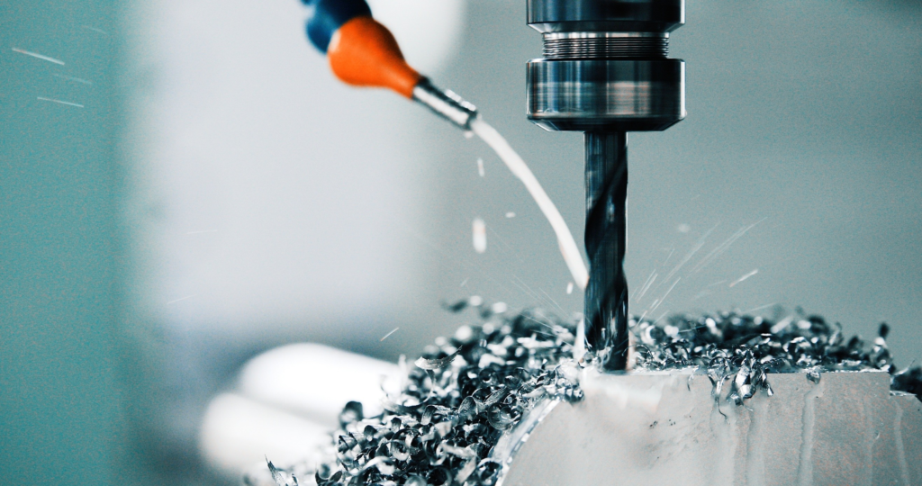
A drill that works well in a maintenance shop may be a costly choice on a machining center. The reverse is also true: a high-performance carbide drill can fail quickly in a flexible hand-held setup where a tougher high-speed steel tool would survive. Drill selection therefore starts with the process, not the catalog description.
For industrial buyers, the useful questions are straightforward. What is the workpiece material? How deep is the hole relative to its diameter? What tolerance and surface finish are required? Can the machine deliver the necessary speed, rigidity, coolant pressure, and runout control? The answers narrow the field much faster than a long list of drill names.
This guide organizes drill bits in three ways: cutting-tool material, tool construction and geometry, and engineering application. It also explains where apparently similar drills create very different costs per hole.
Drill bit classification at a glance
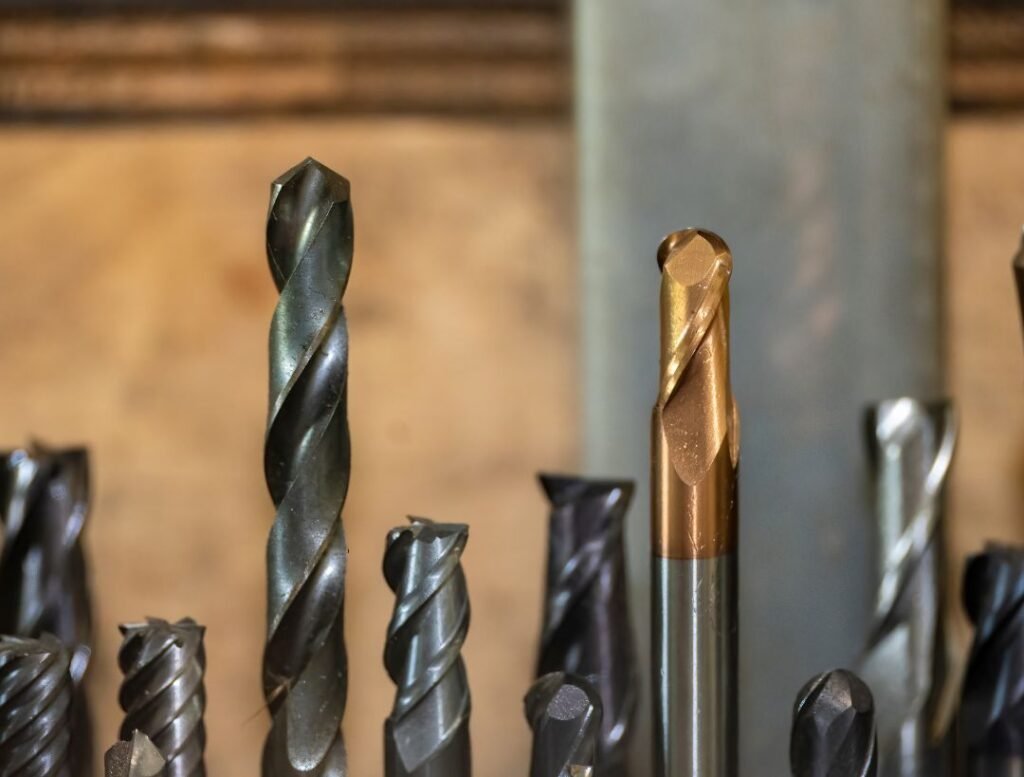
Drill categories overlap. A twist drill describes geometry, while HSS or carbide describes the cutting material. A gun drill describes a deep-hole system and may have a carbide head or a solid-carbide construction. A useful specification should therefore state both the material and the design, such as “solid-carbide, coolant-through twist drill, 8×D.”
Classification basis | Common types | What it tells the buyer |
Cutting material | HSS, cobalt HSS, powder-metallurgy HSS, carbide, PCD, diamond-coated carbide | Heat resistance, toughness, wear resistance, achievable cutting speed, and price |
Construction | Solid, carbide-tipped, replaceable-tip, indexable insert | Diameter range, replacement cost, rigidity, and inventory strategy |
Geometry | Twist, straight flute, step, center, spade, annular, gun drill, BTA | Chip flow, hole depth, entry behavior, hole form, and machine requirements |
Application | Metal, composite, wood, masonry, glass and tile, rock drilling | Cutting mechanism and the workpiece failure mode the tool must control |
Drill types by cutting material
High-speed steel drills
High-speed steel (HSS) is still the baseline material for general-purpose drilling. It is less rigid and less wear-resistant than carbide, but it is comparatively tough, inexpensive, easy to regrind, and tolerant of interrupted manual feed or modest machine runout. Those properties matter in repair shops, fabrication work, portable drilling, and low-volume production.
Standard HSS suits mild steel, aluminum, plastics, and other readily machined materials at moderate speeds. Cobalt-alloyed HSS grades improve hot hardness for stainless steels and higher-strength alloys, but they do not turn an unstable setup into a high-production process. Powder-metallurgy HSS offers a more uniform carbide distribution and a useful balance of toughness and wear resistance for demanding small-batch work.
Select HSS when flexibility and edge toughness matter more than maximum output. It also makes sense when the machine cannot exploit carbide cutting speeds or when a long, small-diameter drill would be vulnerable to shock.
Solid-carbide drills
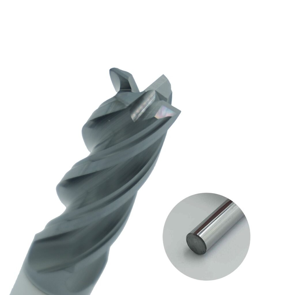
Solid carbide provides the rigidity, compressive strength, and hot-wear resistance needed for productive CNC drilling. Compared with HSS, it supports higher cutting speeds and holds size longer in stable production. Modern designs often combine material-specific point geometry, polished or engineered flutes, internal coolant, and a coating matched to the workpiece.
That performance comes with conditions. The spindle, holder, and workholding must control runout and vibration. A carbide drill is less forgiving of misalignment, loose fixturing, and impact. It should not be chosen only because the workpiece is “hard”; the entire system must support it.
Replaceable-tip and indexable drills
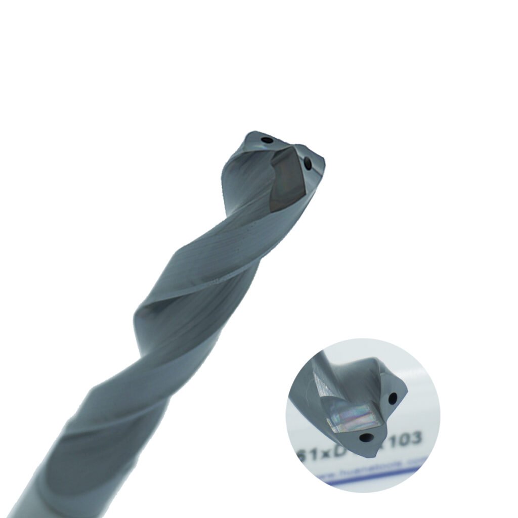
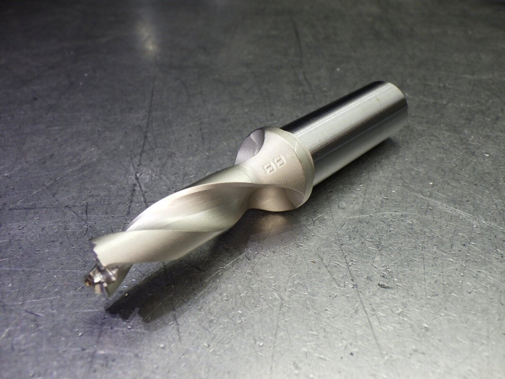
Replaceable-tip drills place carbide at the cutting end while retaining a reusable steel body. They cover a useful middle ground between solid-carbide and indexable tools: a shop can replace a worn tip without resetting a complete drill body, while the full-width tip can produce a cleaner hole than many two-insert indexable designs.
Indexable drills use replaceable carbide inserts in a steel body. They are attractive at larger diameters and high metal-removal rates because insert replacement is economical. Their hole tolerance and finish are generally less refined than those of a well-applied solid-carbide drill, so a boring or reaming operation may still be required.
PCD and diamond-coated drills
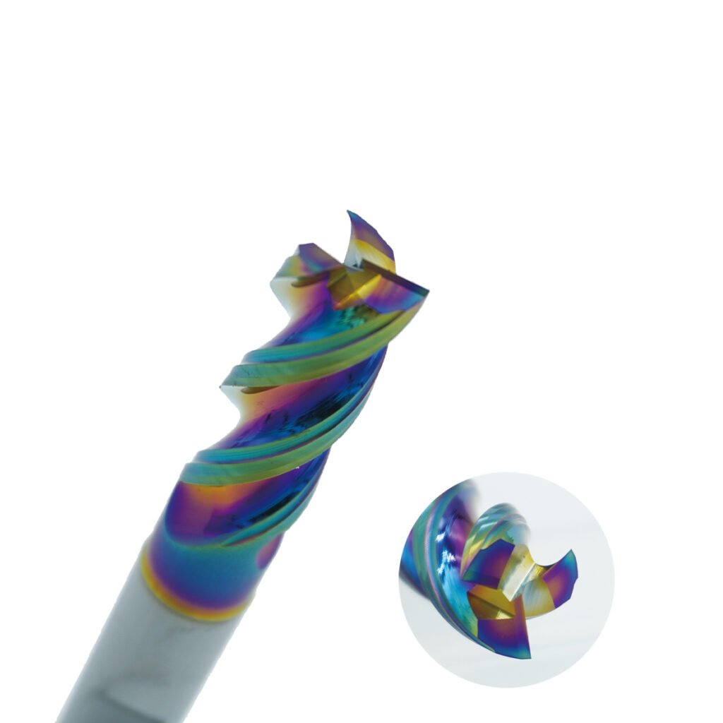
Polycrystalline diamond (PCD) and CVD diamond coatings are used where abrasive non-ferrous materials or composites wear carbide rapidly. Typical workpieces include carbon-fiber-reinforced polymer (CFRP), graphite, high-silicon aluminum, and metal-matrix composites.
PCD is not a universal “hardest material” upgrade. Diamond reacts unfavorably with ferrous materials at cutting temperature, so these tools are normally reserved for non-ferrous and composite applications. Geometry also matters as much as tool material in CFRP: the cutting edge must limit delamination, fiber pull-out, and exit damage.
Drill types by geometry and construction
Twist drills
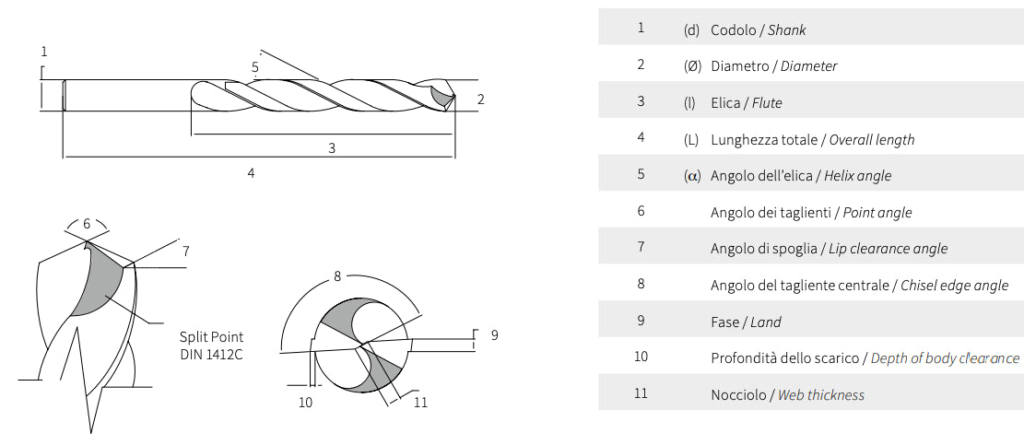
The twist drill is the most common holemaking design. Its point creates the hole, margins guide the body, and helical flutes carry chips away. Point angle, helix angle, web thickness, margin design, edge preparation, and flute finish all influence performance.
A general-purpose 118° point remains common in HSS jobber drills. CNC carbide drills often use split points and application-specific point angles to reduce thrust, improve centering, or strengthen the corner. Aluminum benefits from free-cutting geometry and polished flutes that discourage built-up edge. Stainless steel needs a sharp but supported edge, positive cutting action, and a feed high enough to avoid rubbing and work hardening.
Center drills, spotting drills, and step drills
A center drill creates a protected center hole for turning operations; it is not simply a short spotting drill. A spotting drill establishes an accurate entry for a following drill. Its point angle should be selected with the next tool in mind, because an unsuitable contact sequence can load the drill corners first.
Step drills combine diameters or add a chamfer in one pass. They can reduce cycle time and positional stack-up in stable production, but regrinding and inspection are more involved. The economic case is strongest when the combined features repeat across a meaningful batch.
Spade, annular, and flat-bottom drills
Spade drills use a replaceable blade and are useful for relatively large holes, older machines, and applications where low tooling cost matters more than fine finish. Annular cutters remove only a ring of material, leaving a slug; magnetic-base drilling and structural fabrication are common uses. Flat-bottom geometries help produce near-flat hole bottoms, drill across interruptions, or prepare controlled seats, but they need sufficient rigidity and careful entry conditions.
Gun drills and BTA deep-hole systems
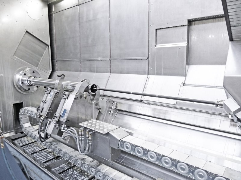
Deep-hole drilling is a process system rather than a long version of a jobber drill. As the length-to-diameter ratio increases, chip evacuation, coolant delivery, guidance, and straightness become dominant constraints.
Gun drills use an asymmetric cutting head, guide pads, an internal coolant channel, and an external chip groove. On CNC equipment, they normally enter a closely controlled pilot hole at low speed before coolant pressure and cutting speed are increased. BTA systems are typically used for larger diameters and high-production deep bores; chips flow through the tool or drill tube depending on the system arrangement.
Matching drill type to the engineering application
Application | Practical first choice | Selection focus |
Mixed repair and fabrication | HSS or cobalt HSS twist drill | Toughness, resharpening, portable-machine stability |
Repeated CNC holes below medium diameter | Solid-carbide coolant-through drill | Runout, point geometry, coating, coolant delivery |
Medium diameters with frequent tip replacement | Replaceable-tip drill | Body stability, tip range, inventory, repeatability after change |
Large-diameter rough holes | Indexable or spade drill | Machine power, insert economy, downstream finishing |
Holes above roughly 10×D | Deep-hole carbide drill or gun drill | Pilot hole, pressure and flow, filtration, straightness |
CFRP or abrasive non-ferrous composite | PCD or diamond-coated carbide | Delamination, fiber exit quality, abrasive wear, dust control |
Concrete and masonry | Carbide-tipped percussion drill | Hammer compatibility, reinforcement risk, dust extraction |
Glass and tile | Diamond or spear-point tile drill | Low thrust, cooling, surface support, breakout control |
Automotive and general production machining
Engine blocks, transmission housings, manifolds, and hydraulic components contain many holes but rarely share one ideal drill. Cast iron favors geometries and grades that tolerate abrasive graphite and short chips. Aluminum calls for polished chip spaces and strong evacuation to prevent chip packing. Steel components may justify solid-carbide or replaceable-tip drills depending on diameter, depth, batch size, and required hole quality.
Buyers should compare cost per acceptable hole, not tool price alone. Include tool-change time, presetting, scrap risk, regrind logistics, and any secondary boring or reaming operation.
Aerospace and composite structures
Aerospace drilling frequently involves titanium, nickel alloys, CFRP, and stacked materials. The challenge is often the transition between layers: a geometry that cuts carbon fiber cleanly may create a burr in the metal layer, while heat generated in titanium can damage the composite interface. PCD, diamond-coated carbide, and stack-specific replaceable tips are used when volume and quality justify them. Process validation should measure entry and exit damage, diameter, roundness, burr height, and tool wear rather than relying on diameter alone.
Mold, die, and energy components
Cooling channels, oil passages, and instrumentation bores can push hole depth well beyond conventional drilling practice. A pilot hole, high-pressure filtered coolant, precise alignment, and controlled entry are part of the tool application. A long drill without those supporting conditions is a failure mode waiting to happen.
Construction, woodworking, glass, and rock drilling
These tools should not be grouped with metalcutting drills simply because they rotate. Masonry bits remove brittle material under percussion. Brad-point and Forstner bits control entry and produce clean holes in wood. Diamond core bits grind hard ceramic, glass, or concrete. Button and cross bits fracture rock in mining and geotechnical work. Each relies on a different cutting or fracture mechanism, so metal-drilling speeds and feeds do not transfer.
A practical drill selection workflow
Start with the drawing and process capability rather than a preferred tool brand.
- Define the finished hole: diameter, depth, tolerance, straightness, surface finish, bottom form, entry and exit condition, and whether the hole is interrupted.
- Identify the workpiece: ISO material group is a useful start, but hardness, abrasive phases, heat treatment, stack construction, and tendency to work-harden also matter.
- Check the machine: spindle power and speed, toolholder accuracy, coolant pressure and flow, filtration, workholding rigidity, and allowable tool length.
- Choose the construction: HSS for flexible low-volume work; solid carbide for stable, accurate CNC production; replaceable-tip or indexable for favorable diameter economics; deep-hole tooling when guidance and evacuation dominate.
- Validate with controlled trials: inspect wear, chip shape, hole size, roundness, finish, burrs, and spindle load. Change one variable at a time.
Symptom | Likely causes | First checks |
Oversize or tapered hole | Runout, misalignment, worn margins, weak fixturing | Holder condition, spindle alignment, clamping, drill wear |
Chipped carbide corners | Impact on entry or exit, excessive runout, unstable workpiece | Entry surface, holder runout, feed at breakthrough, fixture support |
Long chips or chip packing | Wrong geometry, low feed, insufficient coolant flow | Chip form, flute loading, pressure and flow, peck strategy |
Built-up edge in aluminum | Heat, poor lubrication, rough flute surface | Coolant concentration, polished geometry, cutting speed |
Rapid wear in CFRP | Abrasion, unsuitable edge material, poor dust removal | Diamond/PCD option, edge condition, extraction and inspection interval |
What to put on a drill RFQ
A useful request for quotation includes the workpiece grade and hardness, hole diameter and depth, tolerance, surface finish, entry and exit geometry, annual volume, machine type, holder interface, coolant capability, and current process result. For a special drill, add a marked drawing and state which dimensions are functionally critical.
Avoid asking suppliers for “the best carbide drill” without process data. A responsible recommendation may differ by machine and batch size even when the nominal hole is identical. HNCarbide can review the application data and propose a solid-carbide drill geometry, coating, and coolant configuration for production trials.

Conclusion
Drill-bit classification becomes useful when it leads to a process decision. HSS offers toughness and flexibility. Solid carbide raises output and consistency when the setup is rigid. Replaceable-tip and indexable systems improve diameter economics. PCD and diamond coatings address severe abrasion in non-ferrous and composite materials. Deep-hole tools solve a guidance and evacuation problem that ordinary long drills cannot.
The final choice should be based on the complete holemaking system: tool, holder, spindle, coolant, workholding, workpiece, and inspection plan. That is how a drill specification turns into stable cost per hole.