How to Choose End Mills for Hardened Steel
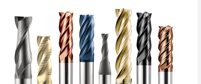
Hard milling failures are often blamed on the coating. In practice, the coating may be the least important part of the mistake. A square end mill can be perfectly suitable for a shallow wall in 45 HRC tool steel and still fail within minutes when the same tool is pushed into a deep slot with excessive overhang. The workpiece condition, cutter profile, carbide grade, edge preparation, flute space, and toolpath all work as a system.
This guide explains how to choose a solid carbide end mill for steels from the pre-hardened range into fully hardened mold and die materials. It focuses on the decisions that affect tool life and dimensional control on the shop floor, rather than treating hardness as the only selection criterion.
Start with the material condition, not the catalog color
The first question is not simply “Is this steel hard?” Record the grade, actual hardness, heat-treatment condition, and whether the cut will cross scale, weld, interrupted surfaces, or hardened pockets. A stable finishing pass in 58 HRC tool steel can be easier on an end mill than an interrupted roughing cut in a softer workpiece.
Hardness changes the balance between wear resistance and edge toughness. As hardness rises, cutting forces become concentrated near a small contact zone, and the tool has less tolerance for runout, impact, or a weak setup. A fine-grain or ultrafine-grain carbide substrate is normally preferred because it can support a hard cutting edge without the bulk and flexibility of high-speed steel. For the upper hard-milling range, use a tool family whose manufacturer explicitly rates the substrate, geometry, and coating for that hardness band.
Workpiece condition | Typical selection focus | Main process risk |
Pre-hardened steel, roughly 30-40 HRC | General-purpose carbide may work; prioritize chip evacuation and stable engagement | Built-up material, chatter, or premature corner wear |
Hardened tool steel, roughly 40-55 HRC | Hard-milling carbide, heat-resistant PVD coating, rigid geometry | Flank wear, edge chipping, deflection |
High-hardness mold steel, roughly 55-65 HRC | Dedicated hard-milling series, short reach, controlled radial engagement | Thermal wear, microchipping, loss of size |
Above about 65 HRC | Manufacturer-rated specialty tools and conservative validation | Rapid edge failure and narrow process window |
These bands are screening ranges, not universal limits. The steel grade, carbide recipe, tool diameter, operation, spindle condition, and engagement can move the practical boundary substantially.
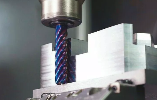
Match the cutter profile to the feature
Tool profile determines where the cutting load enters the tool and what geometry is left on the part. Select it from the feature and toolpath, not from habit.
Square end mills for floors, slots, and sharp shoulders
A square end mill produces a flat floor and a near-sharp internal corner. It is the direct choice for shallow pockets, side walls, and finishing operations that require minimal corner radius. The sharp corner is also the weakest part of the tool. In hard steel, a square end mill is more sensitive to impact and corner chipping than a radiused cutter.
Use it when the drawing requires the geometry. If a small internal radius is acceptable, a corner-radius tool will usually carry load more reliably.
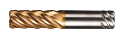
Ball nose end mills for 3D contours
Ball nose tools suit mold cavities, fillets, and sculptured surfaces. Surface finish depends on the programmed stepover and the effective cutting speed at the contact point. Cutting speed approaches zero at the exact center of the ball, so avoid toolpaths that force the tip to do most of the work. Tilting the tool on a multi-axis machine, or selecting a toolpath that moves the contact point away from center, improves cutting action.
For finishing, check the specified ball-radius accuracy as well as overall diameter tolerance. A tool with poor radius form can leave witness lines even when the machine and toolpath are sound.
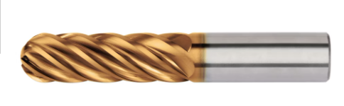
Corner-radius end mills for stronger edges
A corner-radius, or bull nose, end mill bridges the gap between square and ball nose designs. The radius strengthens the corner, reduces the local stress concentration, and is often a better choice for roughing, semi-finishing, and finishing floors where the part permits a fillet.
The radius must still match the part. Do not select a tool radius equal to the specified internal fillet and expect perfect cleanup; leave enough difference for the toolpath to control engagement and avoid rubbing in the corner.
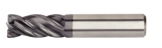
Cutter profile | Best suited to | Advantage in hard steel | Watch for |
Square end | Flat floors, slots, sharp shoulders | Direct geometry and good wall finishing | Fragile corner under impact or full-width engagement |
Ball nose | 3D surfaces, molds, dies, fillets | Smooth contour generation | Low cutting speed at the tool center and cusp height |
Corner radius | Roughing, semi-finishing, filleted floors | Stronger corner and more stable wear | Part-radius compatibility and excess corner engagement |
Choose the coating as part of a complete tool design
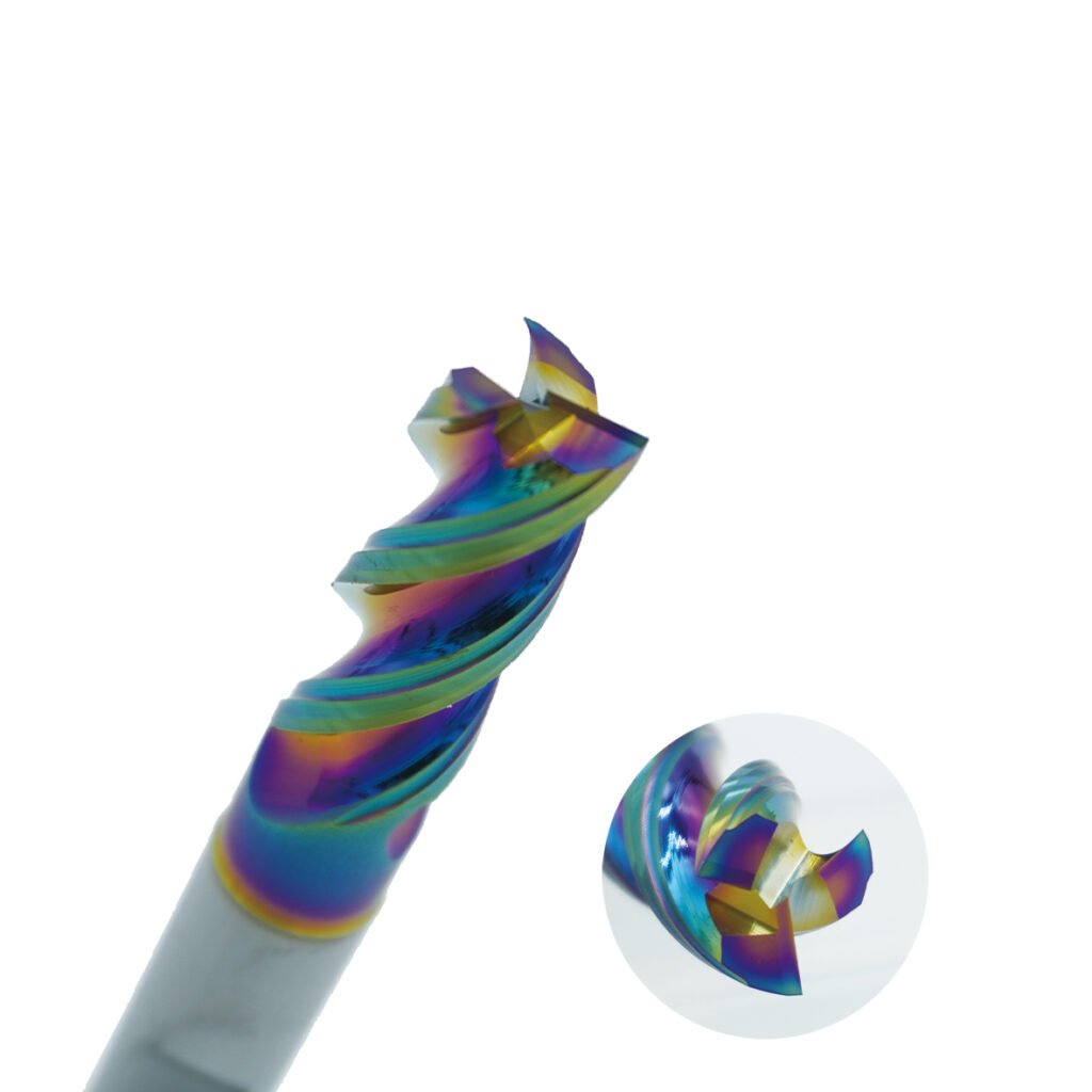
Coating names are useful, but they do not describe the whole cutting tool. Two tools labeled AlTiN can perform differently because coating architecture, aluminum content, carbide substrate, edge preparation, and post-treatment differ. Manufacturer application data is more reliable than selecting by color.
TiN remains a general-purpose, low-cost coating, but it is rarely the first choice for sustained hard milling because newer aluminum-bearing PVD coatings offer better oxidation and hot-hardness performance. TiCN provides high hardness and abrasion resistance but has a lower-temperature application window than common hard-milling coatings, so it is better suited to moderate-temperature operations.
TiAlN and AlTiN are common starting points for hardened steels. Under heat, their aluminum content supports formation of a protective aluminum-oxide layer. The exact naming convention is not consistent enough to choose a tool by the letter order alone. For steels in the upper hardness range, modern AlCrN-, TiSiN-, or nanocomposite-based systems may be offered, but the correct choice still depends on the supplier’s tested application range.
Coating family | Practical use | Limitation to check |
TiN | General-purpose machining at moderate heat | Usually not the first choice for high-speed hard milling |
TiCN | Abrasive wear resistance in lower-temperature cuts | Lower oxidation resistance than aluminum-rich hard-milling coatings |
TiAlN / AlTiN | Common choice for hardened steel and dry or near-dry cutting | Performance varies by coating architecture and tool design |
AlCrN / TiSiN / nanocomposite systems | Dedicated high-temperature or high-hardness applications | Use only within the tool maker’s material and hardness guidance |
Flute count, core size, and chip space must fit the operation
More flutes increase core area and can raise feed capacity when radial engagement is light. They also reduce flute space. That tradeoff matters in slots, deep pockets, and any cut where chips can be recut.
For full-width slotting or unstable roughing, a lower flute count and more chip space are safer. For high-speed finishing or dynamic milling with low radial engagement, four, five, or more flutes may improve rigidity and productivity. Diameter matters: a six-flute 12 mm tool and a six-flute 3 mm tool do not have the same chip space or strength.
Variable pitch and variable helix geometries can reduce regenerative chatter, but they cannot compensate for a loose holder, poor runout, or excessive stickout. Check whether the tool is center-cutting if it must ramp or interpolate into a closed pocket.
Keep the reach as short as the feature allows
Tool deflection rises sharply with overhang. For a simplified cantilever model, deflection is proportional to the cube of unsupported length. Doubling overhang can therefore produce roughly eight times the deflection under the same load. Real cutting systems are more complicated, but the direction is clear: unnecessary reach is expensive.
Select the shortest flute length that clears the axial depth of cut and the shortest overall reach that avoids the part and holder. A long-flute tool is not a substitute for a long-neck tool. When deep reach is required, a reduced neck can provide clearance while preserving a short cutting edge, and a tapered neck can add stiffness where the part geometry permits it.
Runout deserves the same attention. On a small-diameter tool, a few micrometers of runout can shift most of the load onto one flute. Clean the holder and shank, use a capable collet or shrink-fit/hydraulic system, and measure assembled runout near the cutting end when the job is critical.
Select a machining strategy that protects the edge
A dedicated hard-milling cutter can still fail under a poor toolpath. Full-width slotting produces high and changing engagement. When possible, use a constant-engagement or trochoidal strategy with low radial depth and sufficient axial engagement. This reduces force peaks and makes heat generation more predictable.
Climb milling is usually preferred on a rigid CNC machine with controlled backlash. Program smooth entries, avoid burying the tool in internal corners, and reduce engagement before the tool reaches a tight radius. Air blast is often useful for clearing hard chips and keeping thermal conditions steady. Flood coolant can work when the tool maker recommends it and delivery is continuous, but intermittent coolant may impose thermal cycling on a hot carbide edge. Do not switch casually between wet and dry running in the same validated process.
Starting parameters should come from the exact tool maker’s data for the material group and hardness. Apply chip-thinning compensation when radial engagement is low; otherwise, the actual chip may become too thin and the edge may rub rather than cut.
A practical selection sequence
- Confirm the steel grade, measured hardness, heat-treatment state, and any interrupted surfaces.
- Define the operation: slotting, roughing, semi-finishing, wall finishing, floor finishing, or 3D contouring.
- Choose square, ball nose, or corner radius geometry from the feature requirements.
- Select a manufacturer-rated carbide grade and coating for the hardness band and cutting environment.
- Choose flute count from engagement and chip-evacuation needs, then confirm the tool is center-cutting if required.
- Minimize flute length and overhang; use a long-neck or tapered-neck design only when clearance demands it.
- Check holder condition, assembled runout, spindle capability, workholding, and toolpath engagement.
- Start from supplier cutting data, document wear, and adjust one variable at a time.
Troubleshooting early failures
Symptom | Likely causes | First checks |
Edge chipping | Runout, interrupted entry, excessive chip load, weak corner | Holder cleanliness, entry move, corner radius, feed per tooth |
Rapid flank wear | Excess speed, unsuitable coating or grade, rubbing | Cutting speed, radial engagement, chip-thinning compensation |
Chatter or poor wall finish | Excess overhang, low rigidity, unstable engagement | Shorten reach, improve holding, change toolpath or pitch geometry |
Chips welded or recut | Inadequate evacuation, too many flutes for the cut | Air blast, flute space, pocket clearing, radial engagement |
Size drift during finishing | Tool deflection, wear, heat, radius-form error | Stock allowance, tool condition, finish-pass load, tool accuracy |

Final recommendation
The most reliable hard-milling tool is not automatically the hardest coating or the cutter with the most flutes. It is the shortest, most rigid tool that produces the required feature, evacuates chips at the planned engagement, and has a substrate and coating validated for the actual workpiece hardness.
For production work, send the tool supplier the material grade, hardness, feature drawing, machine spindle details, holder type, depth of cut, radial engagement, and coolant plan. HNCarbide can use that information to recommend a square, ball nose, or corner-radius carbide end mill and provide a realistic starting window for trials.