End Mill Use and Selection Guide for CNC Milling
Table of Contents
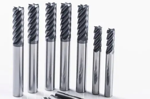
End mill problems rarely begin with the coating. A slot fills with chips because the tool has too little flute space. A long-reach cutter chatters because the setup lacks stiffness. A sharp square corner chips in stainless steel because the edge is being asked to survive an interrupted, high-load entry. Changing the coating may postpone the failure, but it does not fix the mismatch.
This guide explains what an end mill can do, how common geometries differ, and how to choose a tool that suits the operation, material, machine, and production target. It is written for CNC machinists and process engineers, but it also gives tooling buyers a practical way to compare supplier proposals.
What is an end mill?
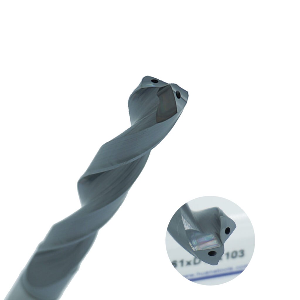
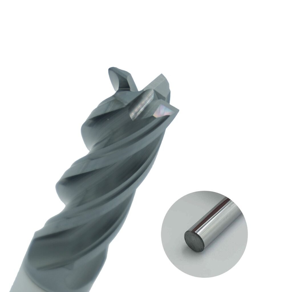
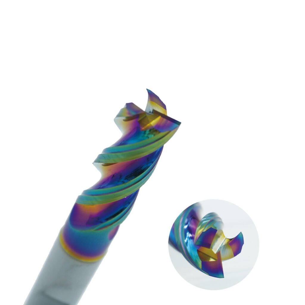
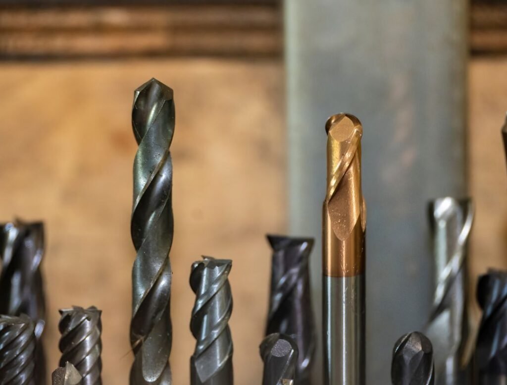
An end mill is a rotating milling cutter with cutting edges on its periphery and, in most designs, across part of the end face. It is used on machining centers, CNC routers, conventional mills, and sometimes live-tool lathes. Depending on its geometry, the same tool family can machine shoulders, slots, pockets, contours, chamfers, and three-dimensional surfaces.
The important phrase is “depending on its geometry.” A cutter that looks suitable in a product photo may be wrong for plunging, full-width slotting, or finishing a deep wall. Before choosing an end mill, check where its cutting edges are located, whether it is center cutting, how much chip space it provides, and how its core changes along the cutting length.
Slot drill vs end mill: the distinction is less rigid than it sounds
The term slot drill traditionally describes a two-flute, center-cutting milling cutter that can plunge into solid material and then move laterally to produce a slot. The unequal end teeth on older designs allowed one edge to cross the tool center. Traditional multi-flute end mills were often non-center-cutting and needed a predrilled entry hole or a ramp from open space.
Modern catalogs blur that boundary. Two-flute tools are routinely sold as end mills, while many three-, four-, and higher-flute end mills are center cutting and can ramp or plunge within stated limits. Buyers should therefore treat “slot drill” as a useful historical category, not a complete technical specification.
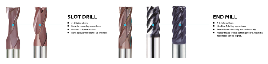
For an actual job, ask more precise questions:
- Does the tool have a center-cutting end geometry?
- Is straight plunging allowed, or does the maker recommend ramping or helical interpolation?
- What maximum ramp angle and axial step are permitted?
- Is the flute space sufficient for a full-width slot at the required depth?
If the data sheet does not answer those questions, the name alone is not enough.
How flute count changes cutting behavior
Flute count changes two things at once. Adding flutes puts more cutting edges around the tool and usually leaves a larger carbide core. That can increase stiffness and feed capacity. The price is smaller flute valleys, which leave less room for chips.
This tradeoff explains why low-flute tools remain common in aluminum and deep slotting. Aluminum often produces bulky, continuous chips, so polished two- or three-flute geometries help prevent chip packing and built-up edge. Steel profiling with light radial engagement can use four, five, six, or more flutes because the chips are smaller and the stronger core supports the tool. Harvey Performance makes the same point in its flute-count guidance: more flutes generally mean a larger core and less chip space, so material and operation must be considered together.
Operation and material | Practical starting point | Why it works | Main risk to watch |
Full slot in aluminum | 2-3 flutes, polished gullets, sharp edge | Large flute valleys clear bulky chips | Built-up edge or recutting if chips remain in the slot |
Side milling general steel | 4-6 flutes, coated carbide | More edges and a stronger core support productive feed | Heat and chatter if radial engagement is too high |
Stainless steel profiling | 4-6 flutes with sharp, material-specific geometry | Controlled chip formation limits rubbing and work hardening | Dwelling, weak entry moves, or inadequate coolant direction |
Deep pocket roughing | Lower flute count or a high-efficiency toolpath with controlled engagement | Keeps chip flow manageable over a long cutting length | Chips trapped below the tool and excessive overhang |
Finishing a stable wall | Higher flute count with low runout | More cutting edges can raise feed while engagement stays light | One overloaded flute if holder runout is excessive |
Do not select flute count from the material name alone. A five-flute tool may work well in high-efficiency milling of steel with a small radial step-over, yet fail immediately in a deep full-width slot because the chips have nowhere to go.
General-purpose and high-performance end mills
A general-purpose end mill uses a geometry intended to work acceptably across several materials and operations. It is useful for maintenance work, job shops with mixed orders, and buyers who want to keep inventory under control. The compromise is that it rarely provides the highest metal-removal rate in a specific alloy.
A high-performance tool is usually designed around a narrower application window. Variable helix and unequal flute spacing can disrupt the repeating cutting forces that cause chatter. A reinforced core may improve bending resistance. Material-specific edge preparation, flute polish, relief angles, and coatings control adhesion, heat, or abrasive wear.
These features only help when the process matches the design. A variable-helix steel end mill is not automatically a good aluminum slotting tool. Likewise, a heavy-core cutter can be very stable in side milling but may have insufficient chip space for aggressive slotting.
Some suppliers use terms such as “double core” for a proprietary internal profile or a changing core thickness. It is not a universal geometry standard. Ask for a cross-section, intended engagement, and application data rather than comparing names across brands.
HSS, powder-metal, or solid carbide?
The cutting material should suit the machine as well as the workpiece. Carbide offers high hot hardness and wear resistance, but its productivity depends on a rigid spindle, sound workholding, low runout, and a holder that can transmit the programmed load. High-speed steel is slower but tougher and more tolerant of interrupted manual feeds and older machines.
Powder-metallurgy high-speed steel, often sold as PM-HSS or PM-HSS-Co depending on composition, sits between conventional HSS and carbide in many applications. Its fine, uniform structure can improve wear resistance and toughness compared with conventional HSS. It is useful when solid carbide is too brittle for the setup or when the spindle cannot exploit carbide cutting speeds.
Tool material | Best fit | Strengths | Limitations |
Conventional HSS | Manual mills, repair work, low spindle speed, unstable feed | Tough, economical, easy to regrind | Lower cutting speed and wear resistance |
Powder-metal HSS | Mixed manual/CNC work, interrupted cuts, moderate production | Better wear resistance than conventional HSS while retaining useful toughness | Usually slower than carbide and not as widely stocked |
Solid carbide | Rigid CNC machines, production milling, small precision features | High cutting speed, stiffness, wear resistance, and geometry control | Sensitive to runout, impact, poor clamping, and excessive overhang |
Carbide grain size is only one part of grade selection. Binder content, edge preparation, coating, and geometry all affect the final balance between toughness and wear resistance. Claims such as “nano grain equals highest performance” are too broad unless the application and grade design are also stated.
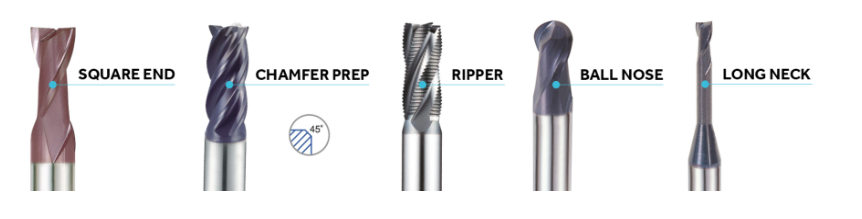
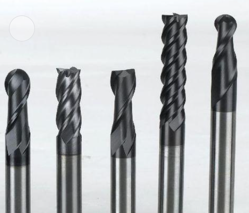
Common end-mill end styles and where they fit
Square end mills
A square end mill produces flat floors and nominal 90-degree walls. It is the default choice for pockets, shoulders, and general profiling when a sharp internal corner is required. The sharp corner is also the weakest point of the tool, so interrupted cuts and heavy entries can chip it.
Corner-chamfer and corner-radius end mills
A small chamfer or radius strengthens the cutting corner. That usually improves edge reliability in steel, stainless steel, titanium, and roughing cuts. The reinforced corner may allow a more stable process, but it also changes the part geometry. Confirm that the drawing permits the resulting fillet or chamfer.
Roughing end mills
Roughers have serrated or profiled cutting edges that divide the chip and reduce cutting force. They can remove material efficiently on machines that would struggle with a smooth-edge tool at the same engagement. A rougher normally leaves a textured surface, so a finishing allowance should remain for a separate tool.
Ball nose end mills
A ball nose tool is used for three-dimensional contours, mold surfaces, fillets, and blended forms. Cutting speed falls toward zero at the tool center, so programming the tool tip directly across a flat surface can cause rubbing and poor finish. Tool tilt, step-over, and the effective cutting diameter should be considered when setting cutting data.
Tapered and long-neck end mills
Tapered end mills support draft-angle walls and narrow, deep features. Long-neck designs reach below obstructions while keeping the cutting length short. Both tools are sensitive to deflection. Use only the reach required, simulate holder clearance, and avoid treating a long-reach tool like a standard stub cutter.
Solid carbide, exchangeable head, or indexable cutter?
This choice is mainly about diameter, accuracy, reach, replacement cost, and the way the shop manages tools.
Solid-carbide end mills are common at small diameters and where wall quality, runout control, or a sharp continuous edge matters. They can produce an excellent finish and complex flute geometry. When worn, the complete tool is replaced or reconditioned.
Exchangeable-head systems use a reusable shank and a replaceable solid cutting head. The shank can remain in the holder while the worn head is changed, reducing carbide consumption and sometimes limiting remeasurement. They are especially useful for long reaches and repeated jobs where a standardized shank platform reduces inventory.
Indexable cutters use mechanically clamped inserts in a reusable body. They are attractive for larger diameters, heavy roughing, and production where cost per cutting edge matters. Insert pockets and edge preparation make it harder to reproduce the sharp, uninterrupted geometry of a small solid tool, so solid carbide often retains an advantage on small features and demanding finishes.
Seco’s current comparison places these systems in overlapping rather than fixed diameter ranges: solid tools dominate small diameters, exchangeable heads bridge many intermediate applications, and indexable cutters become increasingly attractive as diameter and material-removal demand grow. A 20 or 25 mm boundary can be a useful estimating point, but it should not be treated as a rule.
Decision factor | Solid carbide | Exchangeable head | Indexable cutter |
Small features and tight radii | Strongest option | Limited by head range | Usually unsuitable at very small diameter |
Surface finish and wall quality | Excellent with low runout | Often close to solid-tool performance | Depends on insert seating, runout, and wiper geometry |
Long reach | Can be costly and fragile | Reusable long shanks are a practical strength | Available, but body and insert size may limit access |
Heavy roughing at larger diameter | High performance but high carbide cost | Useful in the intermediate range | Strong economics and replaceable edges |
Changeover and inventory | Whole tool is changed or reground | Head changes on a common shank | Inserts are indexed or replaced in a common body |
Cost metric to track | Cost per regrind and tool life | Head cost, shank life, and repeatability | Cost per usable insert edge and body life |
A practical end-mill selection sequence
1. Start with the feature and toolpath
Define whether the tool will slot, profile, finish a wall, rough a pocket, machine a 3D surface, or plunge. Note radial engagement, axial depth, entry method, corner radii, reach, and whether chips can escape. This step normally eliminates more candidates than the coating choice.
2. Set the diameter and required reach
Use the largest diameter that fits the feature and corner requirements without forcing excessive engagement. Keep overhang as short as possible. Tool deflection rises quickly as the unsupported length grows, so an unnecessary extension can erase the rigidity gained from carbide or a high-performance geometry.
3. Match geometry to the workpiece material
Aluminum benefits from sharp edges, open polished flutes, and geometries that resist built-up edge. Steel needs a useful balance of core strength and chip space. Stainless steel and heat-resistant alloys demand controlled engagement, sharp but supported edges, and cutting data that prevent rubbing. Graphite and composites may require abrasion-resistant grades or diamond-based solutions.
4. Check the machine, holder, and workholding
Confirm spindle speed, power, taper size, coolant or air delivery, holder condition, fixture stiffness, and programmed acceleration. Carbide needs secure clamping. A hydraulic chuck, shrink-fit holder, or precision collet can provide good runout control when correctly maintained, but no holder compensates for dirt, a damaged collet, or excessive stick-out.
5. Use the manufacturer’s application window
Start with the maker’s cutting data for the exact tool, material group, and operation. Slotting data should not be copied from light side-milling data. If the catalog does not list the material or entry method, ask the supplier for an application recommendation rather than assuming compatibility.
6. Compare cost per good part
Purchase price is only one line in the calculation. Include cycle time, number of usable edges, regrinding, tool presetting, unplanned stops, scrap risk, and inventory lead time. A more expensive cutter can be cheaper when it removes a tool change or makes tool life predictable. The opposite is also true: a premium tool has little value if the machine cannot hold the required runout or engagement.
Operating checks before the first cut
Clean the tool shank and holder bore. Measure runout as close to the cutting edges as practical, especially for small tools. Confirm that the clamping method and torque follow the holder manufacturer’s instructions. Simulate the toolpath and holder, then verify that the programmed feed is based on the number of effective cutting edges.
Chip evacuation deserves its own check. Air blast, through-tool coolant, external coolant, or minimum-quantity lubrication must reach the cut rather than merely wet the holder. In a deep pocket, plan how chips will leave each level. Recut chips often look like a mysterious coating problem but are fundamentally a toolpath and evacuation problem.
On the machine, listen for a stable cutting sound and inspect early chips. Long welded chips, powdery debris, blue discoloration, or material packed into the flutes are useful warnings. Stop before a damaged edge turns into a broken tool or scrapped part.
Common problems and first corrections
Symptom | Likely cause | First correction |
Chatter bands on the wall | Excessive overhang, weak fixture, resonant speed, too much radial engagement | Shorten the assembly, verify clamping, reduce engagement, or test another speed band |
Chips welded into flutes | Poor evacuation, unsuitable flute count, dull edge, excessive heat | Use a more open geometry, improve air/coolant direction, and check speed and chip load |
One flute wears first | Holder runout, dirty taper or collet, damaged shank | Clean and inspect the system, then measure runout near the cutting edge |
Corner chipping | Sharp weak corner, abrupt entry, excessive chip load, interrupted cut | Use a permitted corner radius or chamfer, smooth the entry, and lower peak load |
Tool pulls from holder | Contaminated shank, inadequate torque, high axial cutting force | Clean the interface, apply specified torque, and use a higher-security holder if needed |
Poor finish after tool change | Insert/head seating error, axial runout, wrong length offset | Clean the interface, verify seating and torque, then remeasure runout and tool length |
Change one variable at a time when production allows it. If speed, feed, depth, coolant, and tool geometry all change in the same trial, a better result will not tell you which correction worked.
Questions buyers should ask suppliers
Ask for the recommended material group, operation, radial and axial engagement, entry method, holder type, and expected runout condition. For a high-performance end mill, request an explanation of what the variable pitch, core design, edge preparation, and coating are meant to accomplish. Those details are more useful than a general claim of higher metal-removal rate.
For exchangeable and indexable systems, confirm the number of usable edges, replacement availability, interface repeatability, spare screws or keys, and whether multiple grades or geometries share the same holder. For solid tools, ask about regrinding limits and whether recoating preserves the original edge preparation.
A production trial should have a written success criterion: parts per edge, cycle time, surface finish, size capability, spindle load, or cost per good part. Without that target, trials tend to favor whichever tool looks best after a short run rather than the tool that makes the process more reliable.

Conclusion
An end mill should be selected as part of a cutting system, not as an isolated catalog item. The feature and toolpath define the basic geometry. Workpiece material and chip flow narrow the flute count and edge design. Machine rigidity, holder runout, reach, and production economics decide whether the tool can deliver its promised performance.
Start with the cut, keep the assembly short, and use supplier data for the exact operation. That approach prevents most expensive surprises before the spindle starts.
HNCarbide supplies solid-carbide end mills and application-specific geometries for machining aluminum, steel, stainless steel, hardened materials, and other demanding workpieces. For a useful recommendation, share the material grade, feature, tool diameter, axial and radial engagement, holder, and machine limits rather than only the requested coating.