Flat, Ball-Nose, Corner-Radius, or Roughing End Mill? A Practical Selection Guide
Table of Contents

A cutter can fit the spindle, reach the feature, and still be the wrong tool for the job. That mismatch often shows up as packed chips in a slot, chipped corners in steel, long cycle times on a 3D surface, or a roughing tool being blamed for the finish it was never designed to produce.
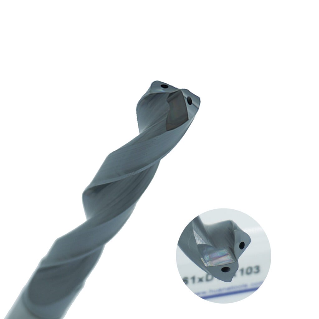
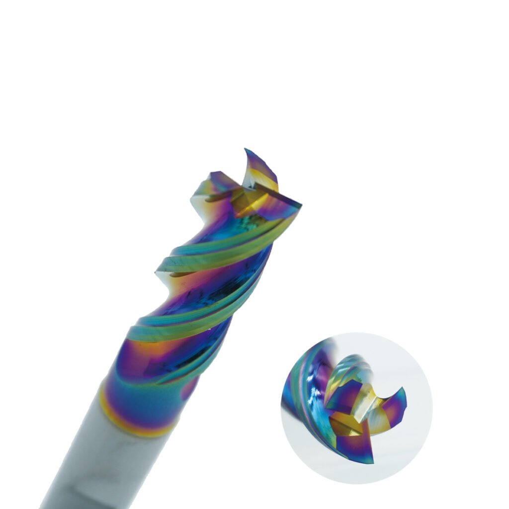
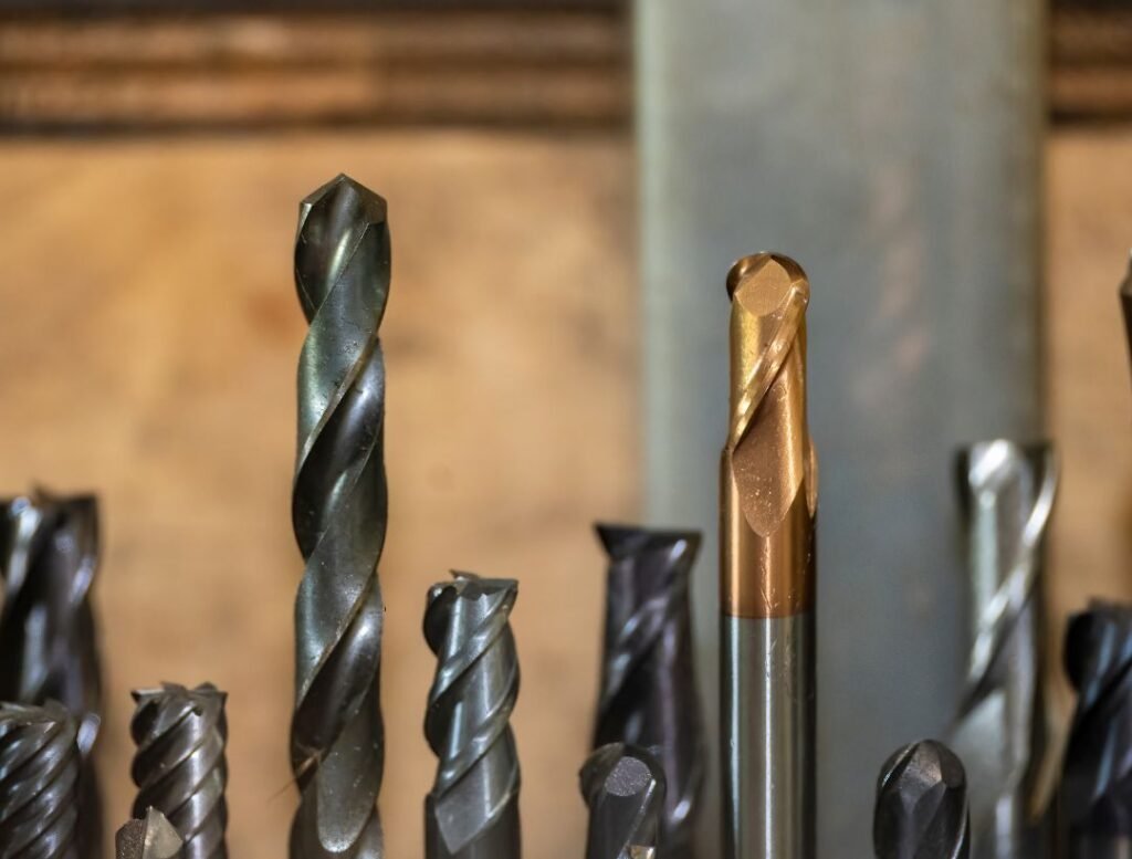
The fastest way to narrow the choice is to start with the shape the tool must leave behind. A square end is built around flat floors and near-square internal corners. A ball nose follows changing surface angles. A corner-radius end mill protects the cutter’s most vulnerable corner while leaving a controlled fillet. A roughing end mill breaks a heavy cut into smaller chips so bulk stock can be removed with lower cutting-force peaks.
Those descriptions are only the first filter. Material, flute count, toolpath, reach, machine rigidity, coolant delivery, and required finish still decide whether a particular cutter will work. This guide connects the four common profiles to real shop-floor decisions and points out where simplified rules can become expensive.
Quick comparison: what each end mill is for
Tool profile | Best first choice for | Main strength | Typical limitation |
Flat (square) end mill | Flat floors, slots, shoulders, side walls | Accurate floor and wall geometry | Sharp corner is vulnerable; slotting can trap chips |
Ball-nose end mill | 3D contours, molds, dies, sculptured surfaces | Continuous contact on changing surface angles | Near-zero surface speed at the center; leaves cusps between passes |
Corner-radius (bull-nose) end mill | Roughing/semi-finishing pockets, strong-edge profiling | Stronger cutting corner and a controlled floor fillet | Cannot produce a sharp 90-degree floor-to-wall corner |
Roughing end mill | Rapid stock removal and heavy roughing | Chip-splitting edge reduces chip size and cutting-force peaks | Leaves a ribbed surface and normally needs a finishing pass |
1. Flat end mills: the default for flat floors and straight walls
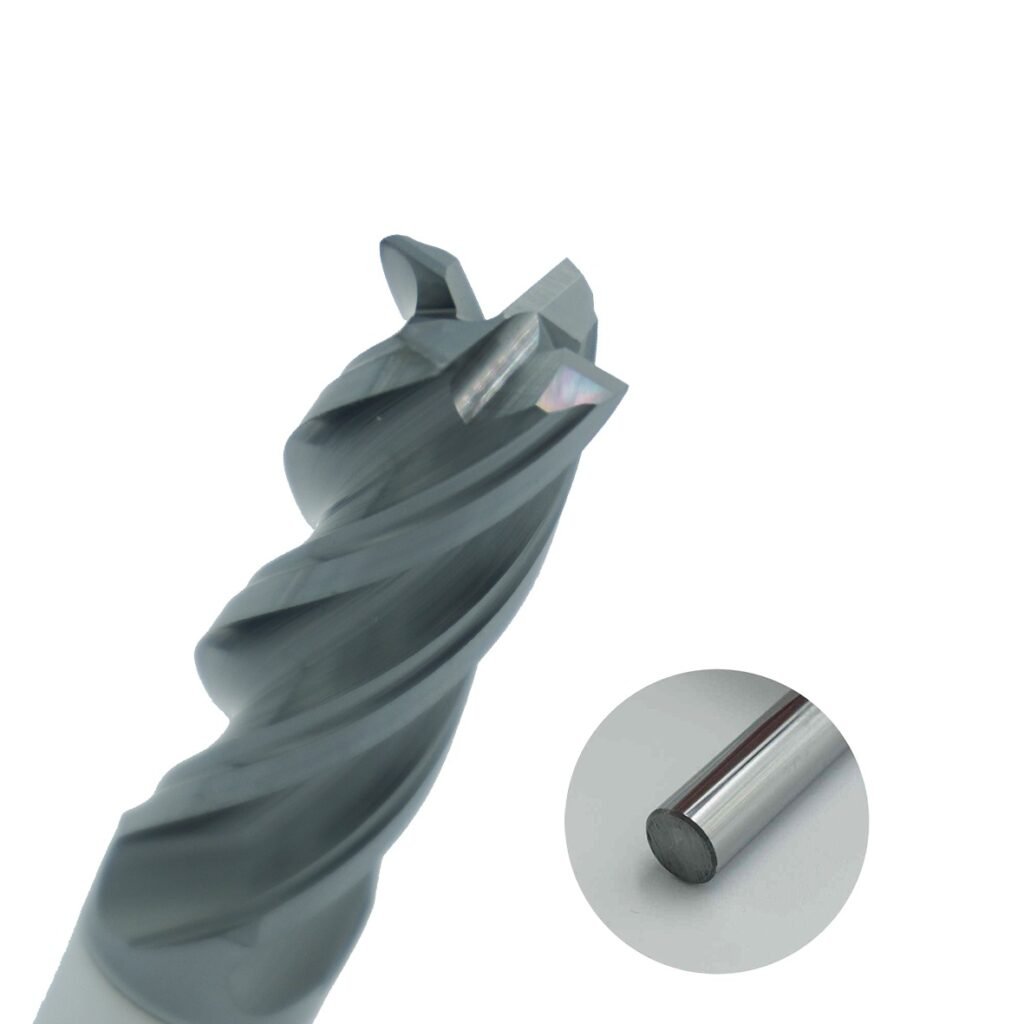
A flat end mill, also called a square end mill, has a cutting end that produces a flat bottom. It is the practical baseline for pockets, shoulders, peripheral milling, face passes with a small-diameter tool, and slots that require a flat floor. If the drawing calls for a square internal corner at the floor, a square end mill is usually needed for the final cleanup pass, even when a stronger corner-radius tool removes most of the stock first.
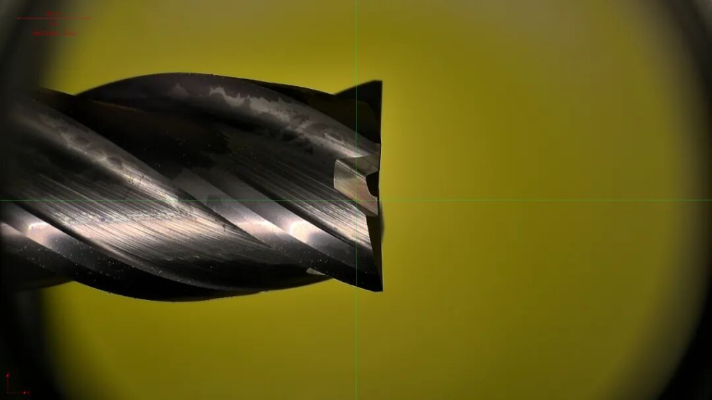
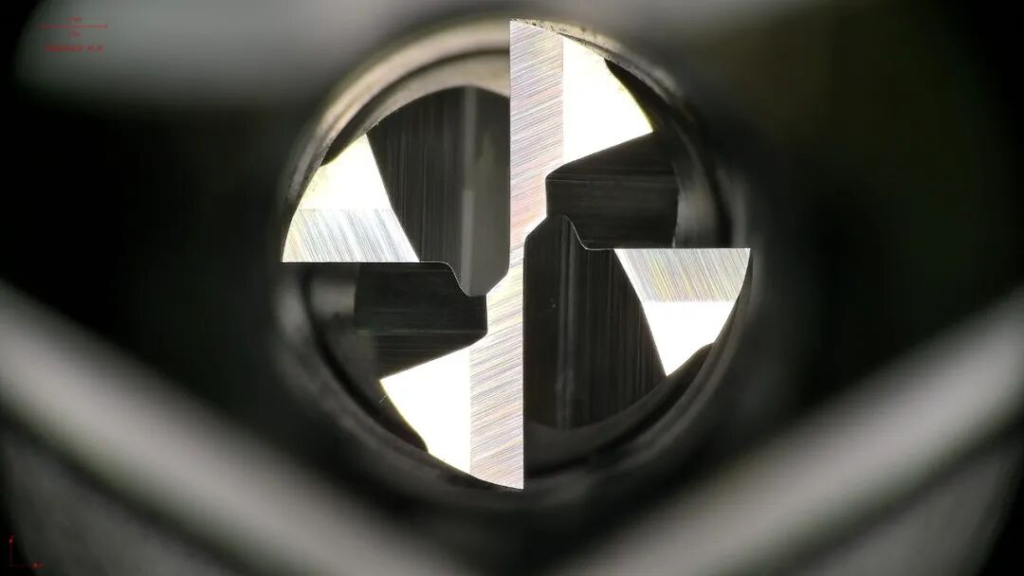
The sharp cutting corner is also the profile’s weak point. Interrupted engagement, excessive runout, chatter, or an aggressive entry can chip that corner before the rest of the flute is worn. For this reason, many shops rough a pocket with a corner-radius tool and reserve the square end mill for the material that must be removed to meet the final corner requirement.
Where a flat end mill works well
- Closed and open slots when the flute space can evacuate the expected chip volume.
- Pocket floors, rectangular cavities, and shoulders that require a flat bottom.
- Side-wall finishing and contouring when tool deflection is controlled.
- Cleanup of internal floor corners after roughing with a radiused tool.
Do not assume every flat end mill can plunge vertically. A center-cutting design, ramp, or helical entry is required. Likewise, a four-flute tool is not automatically a ‘surface milling tool.’ Four flutes can raise potential feed and core stiffness, but they also reduce flute volume. In a full-width slot, especially in aluminum, that smaller chip space may be the limiting factor.
2. Ball-nose end mills: built for 3D surfaces, not flat-floor productivity
A ball-nose end mill has a hemispherical tip. Its contact point moves along the radius as the tool follows a curved surface, making it the familiar choice for mold cavities, dies, impellers, organic forms, and other three-dimensional contours. It can blend changes in surface angle that would create visible steps or gouges with a square tool.
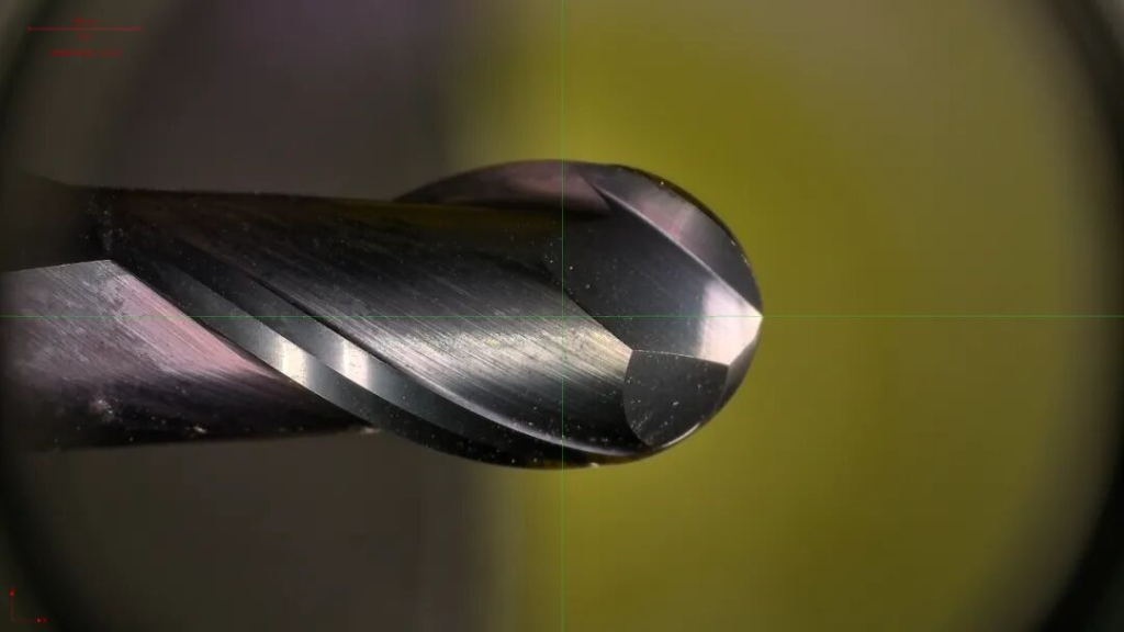
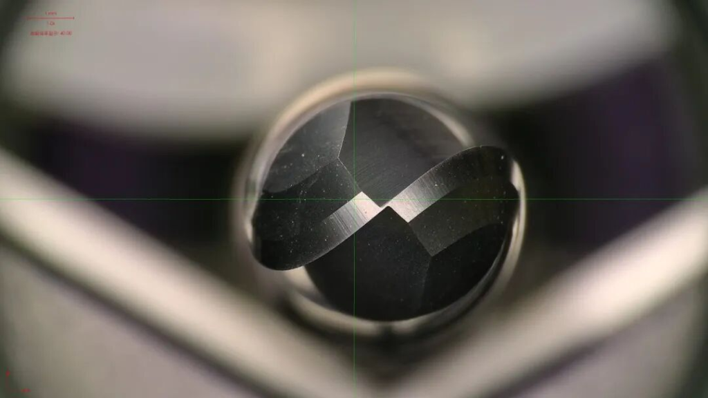
The center of a ball nose is a special case: cutting speed approaches zero at the exact tip. When a toolpath keeps the center on a nearly flat surface, the material may be rubbed or ploughed instead of cleanly sheared. Tilting the tool in five-axis work, machining on the side of the ball where possible, and choosing a suitable lead angle can improve cutting action and finish.
Surface quality also depends on stepover. Adjacent passes leave a scallop, or cusp, whose height changes with tool radius, local surface angle, and radial stepover. A smaller stepover improves finish but increases cycle time. The correct decision is therefore not simply ‘use a ball nose for 3D.’ It is to choose the largest practical tool, avoid poor center contact, and set stepover from the permitted cusp height and polishing allowance.
Where a ball nose works well
- Semi-finishing and finishing mold and die cavities.
- Convex, concave, blended, and free-form surfaces.
- 3D profiling where surface continuity matters more than producing a flat floor.
- Rest machining in radii that a larger tool cannot reach.
3. Corner-radius end mills: stronger corners and controlled fillets
A corner-radius end mill, often called a bull-nose end mill, is not the same tool as a corner-rounding cutter. The corner-radius end mill has a small radius where the end face meets the outside diameter. It mills pockets and profiles while leaving a matching fillet at the floor-to-wall intersection. A corner-rounding cutter is a form tool used to place a radius on an exposed part edge.
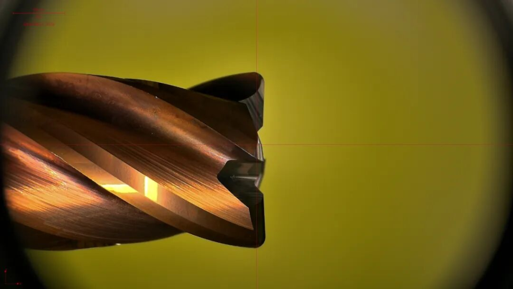

Replacing a sharp corner with a radius distributes load over a broader edge and reduces the tendency for corner chipping. That makes the profile useful for roughing and semi-finishing steel, stainless steel, hardened materials, and interrupted cuts when the part geometry allows a floor fillet. The largest permissible tool corner radius generally provides the strongest edge, but the drawing controls the limit: the cutter radius must not exceed the required internal part radius.
A corner radius can extend usable tool life compared with a square corner under the same application, but no responsible selection guide should promise a universal multiplier. The actual gain depends on substrate, coating, material hardness, engagement, runout, overhang, coolant, and cutting data. It also introduces chip thinning along the radius, so programmed feed should be checked rather than copied blindly from a square-end operation.
4. Roughing end mills: chip control for high stock-removal work
A roughing end mill has serrations, chip splitters, or a wave-style cutting edge along the flute. Instead of forming one wide chip across the entire axial engagement, the edge divides the chip into smaller segments. The result is easier chip handling and lower peak cutting forces, which can help a rigid setup remove heavy stock efficiently.
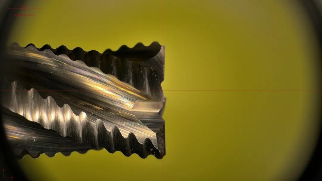
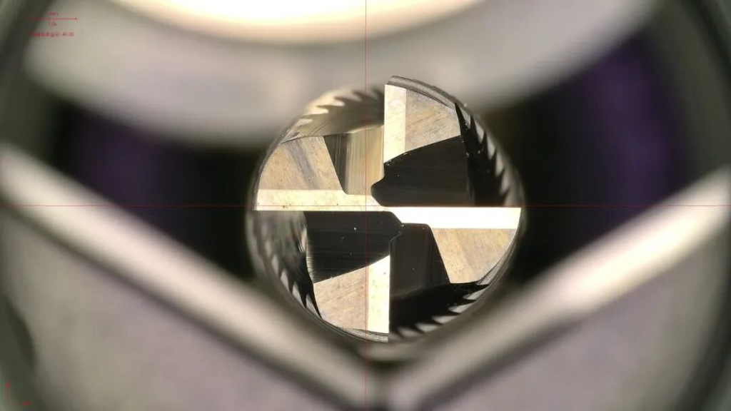
Roughers are useful for removing uneven stock from steel, cast iron, stainless steel, aluminum alloys, and other materials when the cutter grade and geometry match the workpiece. They are not finish tools. The serrated edge transfers a characteristic pattern to the wall and may leave more stock variation than a finishing end mill. Plan a separate semi-finishing or finishing pass with consistent allowance rather than trying to obtain final size and surface quality in the heavy cut.
Traditional full-slot roughing is only one approach. Modern dynamic or trochoidal toolpaths use low radial engagement and greater axial depth, often with purpose-designed multi-flute cutters. In those toolpaths, a high-performance five- or six-flute tool may outperform a conventional coarse-pitch rougher. Match the cutter to the programmed engagement instead of selecting by the word ‘roughing’ alone.
Flute count: use chip volume and engagement, not a two-rule shortcut
The common shortcut says two flutes for slots and four flutes for flat milling. It is a useful memory aid only at the most basic level. Every added flute creates another cutting edge and can support a higher table feed at the same chip load, but it also occupies space that could have been used for chip evacuation. Tool diameter, core size, flute form, helix, coolant, workpiece material, and radial engagement change the answer.
Situation | Likely starting point | Why | Check before release |
Full-width slot in aluminum | 2 or 3 flutes with large gullets | Large chips need open flute space | Built-up edge, coolant/air blast, flute loading |
General steel profiling | 4 flutes | Balanced edge count, core strength, and chip space | Radial engagement, overhang, coating, machine power |
Dynamic milling with low radial engagement | 4-6 flutes in a purpose-built design | More edges can raise feed while engagement stays controlled | CAM path, chip evacuation, holder pullout resistance |
Finishing a wall | 4 or more flutes where chip load permits | More cutting contacts can support productivity and stability | Runout, deflection, finish requirement |
Small deep pocket | Fewer flutes may be safer | Restricted space makes chip evacuation critical | Reach, neck clearance, coolant access |
A practical selection sequence
Question | Decision it controls | Typical warning sign if ignored |
What shape must remain? | Square, ball, corner-radius, or form profile | Wrong floor radius, inaccessible corner, excess polishing |
Is this roughing, semi-finishing, or finishing? | Edge preparation, chip splitter, allowance strategy | Poor finish or premature edge failure |
How much of the cutter is engaged? | Flute count, chip space, feed, entry method | Packed flutes, chatter, broken corners |
What material and hardness? | Substrate, coating, rake, flute geometry | Built-up edge, heat cracking, rapid wear |
What are the machine and setup limits? | Diameter, overhang, holder, cutting data | Deflection, pullout, power overload |
What feature tolerance and finish are required? | Finishing stock, stepover, final tool | Tapered walls, visible cusps, missed size |
Begin with the feature. Use a flat end mill when the final geometry demands a flat floor or square cleanup. Use a ball nose when the tool must follow continuously changing surface angles. Choose a corner-radius tool when a floor fillet is acceptable and edge strength matters. Select a roughing profile when stock removal and chip management dominate, then plan the finishing tool separately.
Next, check the process rather than relying on the tool name. Full-width slotting, light radial profiling, dynamic milling, plunging, and 3D finishing impose different loads. Confirm center-cutting capability for entry moves, keep overhang as short as access allows, use a holder suitable for the cutting forces, and base feed on actual chip load and engagement.
Common selection mistakes
- Calling a corner-radius end mill a corner-rounding cutter. They solve different geometry problems.
- Finishing a broad flat area with the center of a ball nose, where surface speed is lowest.
- Using a high-flute-count tool in a chip-heavy slot without enough flute space or evacuation.
- Expecting a roughing end mill to meet final wall finish and size without a finishing allowance.
- Choosing the longest available tool instead of the shortest tool that reaches the feature.
- Copying speeds and feeds across different diameters, materials, coatings, holders, or engagement conditions.
What B2B buyers should specify
A purchase request that says only ’10 mm carbide end mill’ leaves too much room for mismatch. A useful RFQ states the profile, diameter, corner or ball radius, flute count, flute length, overall length, shank, material and hardness, roughing or finishing duty, coating preference, coolant method, machine interface, and expected operation. For repeat production, include the CAM strategy and current failure mode. That information allows a tooling supplier to recommend a geometry rather than merely quote a diameter.

Conclusion
The four cutters are not interchangeable versions of the same tool. Flat end mills create flat floors and straight walls; ball-nose tools follow 3D surfaces; corner-radius end mills trade a sharp internal corner for a stronger cutting edge; and roughing end mills divide heavy chips to remove stock efficiently. Flute count then fine-tunes the balance among chip space, core strength, feed potential, and stability.
If you are comparing solid-carbide end mills for a production job, HNCarbide can review the workpiece material, feature geometry, engagement, machine limits, and finish target before recommending a profile and flute design. Sending the drawing, material grade, tool diameter, depth of cut, and current problem usually produces a more useful answer than selecting from a catalog image alone.