
Milling Cutters Explained Types Materials and Selection for CNC Machining
Table of Contents
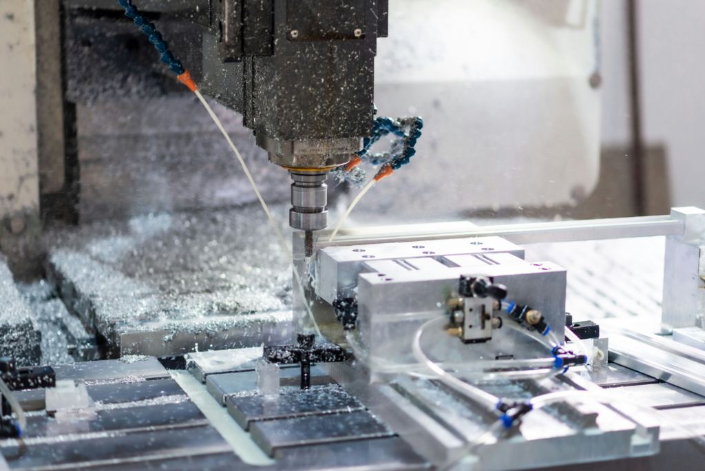
A milling cutter can be inexpensive compared with the machine holding it, yet the wrong cutter quickly becomes the most expensive part of the process. It can add minutes to every cycle, overload the spindle, leave chatter marks, pack a slot with chips, or force an operator to stop a production run for repeated tool changes.
For that reason, choosing a cutter should begin with the feature on the drawing and the conditions around the cut. Diameter and price matter, but so do chip space, edge strength, reach, workpiece material, holder runout, machine power, and the way the cutter enters and leaves the work.
This guide explains the main milling cutter families, how their construction and materials affect performance, and how to make a practical choice for CNC or conventional milling.
What Is a Milling Cutter?
A milling cutter is a rotating multi-edge tool that removes material as its teeth repeatedly enter and leave the workpiece. Unlike a single-point turning tool, several edges may contribute during one revolution. This allows high material-removal rates, but it also makes milling an interrupted process. Every tooth must survive repeated mechanical and thermal loading.
The cutting edges may be located around the cutter’s periphery, across its end face, or in both areas. That placement determines whether the tool is best suited to producing a broad flat face, a shoulder, a slot, a pocket, a profile, or a formed surface.
The word “milling cutter” covers a wide range of tools. A 3 mm solid-carbide end mill used for an electronics housing and a 125 mm indexable face mill used on a machine base belong to the same broad family, but their selection rules are very different.
The Main Milling Cutter Types
Rather than memorizing catalog categories, match the cutter to the surface it must create.
Face mills for broad flat surfaces
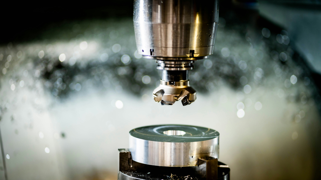
A face mill cuts mainly with edges near the tool face while the cutter axis sits roughly perpendicular to the machined surface. Indexable face mills dominate production work because a large cutter body can carry replaceable carbide inserts. When an edge wears, the operator indexes or replaces the insert instead of discarding the complete tool.
Face mills suit machine bases, valve bodies, plates, castings, and any job that needs a wide flat surface. Cutter diameter, lead angle, insert pitch, spindle power, and workpiece width all matter. A cutter slightly wider than the cut may complete a surface in one pass, but “bigger” is not automatically better. An oversized tool can increase torque demand, engagement, and chatter on a light machine.
End mills for slots, shoulders, pockets, and profiles
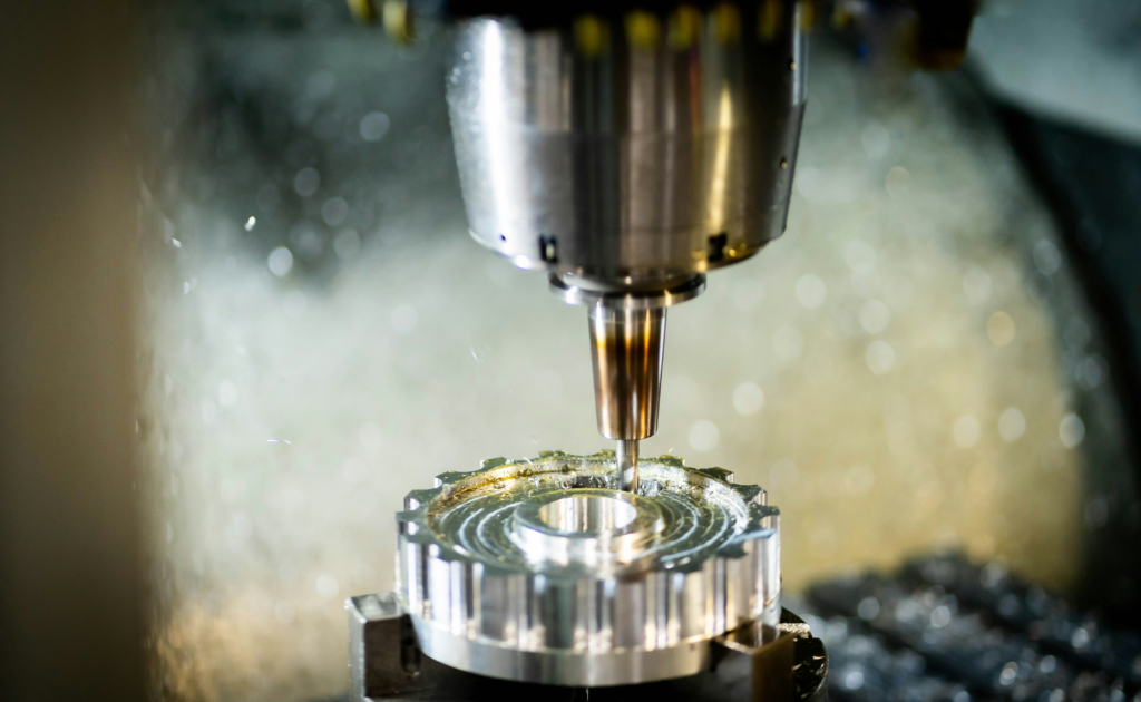
End mills have cutting edges on the cylindrical surface and usually on the end. They are the everyday cutter on vertical machining centers because one tool can machine side walls, pockets, slots, steps, and contoured features.
The end shape changes the job:
- A square end mill produces flat floors and sharp 90-degree corners.
- A corner-radius end mill strengthens the weakest part of the tool and is often more durable in roughing.
- A ball nose end mill is used for 3D contouring, molds, dies, and blended surfaces.
- A chamfer mill prepares edges, countersinks holes, and creates angled features.
Center-cutting geometry is required when the tool must plunge or ramp from the center. A non-center-cutting tool needs another entry method, such as a predrilled hole or side entry.
Slab and cylindrical cutters for peripheral milling
Slab or cylindrical milling cutters carry teeth around their circumference. They are normally mounted on an arbor with the cutter axis parallel to the surface. This remains a productive method for machining long flat surfaces on horizontal mills, especially when the setup can support a wide, rigid cutter.
Coarse-pitch versions provide more chip space and stronger teeth for heavy roughing. Fine-pitch cutters place more edges in contact and can improve finish in stable cuts, but they leave less room for chips.
Side-and-face cutters for deep slots and shoulders
A side-and-face cutter has teeth on its circumference and on one or both sides. The geometry provides clearance while cutting slots, keyways, and shoulder features. Compared with forcing a long end mill through a deep slot, an arbor-mounted side-and-face cutter can offer better stiffness and a shorter force path.
Form, T-slot, dovetail, and other special cutters
Form cutters reproduce a defined profile in the workpiece. T-slot cutters machine the undercut portion of a T-slot after a straight slot has created access. Dovetail cutters generate angled undercuts. Gear cutters, thread mills, woodruff keyseat cutters, and profile cutters solve similarly specific features.
These tools can remove an extra setup or a secondary operation, but they also demand careful attention to entry path, chip evacuation, and replacement availability.
Cutter type | Best matched features | Main selection concern | Common construction |
Face mill | Broad faces and open surfaces | Diameter, insert pitch, lead angle, spindle power | Indexable body with carbide inserts |
Square or corner-radius end mill | Slots, pockets, shoulders, profiles | Flute count, reach, corner strength, chip space | Solid carbide or indexable |
Ball nose end mill | 3D contours, molds, blended surfaces | Effective cutting diameter and step-over | Solid carbide or indexable |
Slab or cylindrical cutter | Long flat surfaces on horizontal mills | Arbor rigidity, tooth pitch, chip capacity | HSS, brazed carbide, or indexable |
Side-and-face cutter | Deep slots, keyways, shoulders | Side clearance, arbor support, slot width | HSS or indexable |
Form or undercut cutter | T-slots, dovetails, radii, custom profiles | Entry method, neck strength, replacement lead time | Solid carbide, HSS, or indexable |
Solid, Brazed, and Indexable Construction
Tool construction changes both cutting behavior and cost.
Solid cutters are ground from one piece of high-speed steel or cemented carbide. They are common at smaller diameters and where sharp, accurate geometry is important. Solid-carbide end mills combine a stiff body with good hot hardness, which supports higher cutting speeds on rigid CNC equipment.
Brazed cutters use carbide tips permanently joined to a steel body. They can be economical for larger tools or special profiles, although regrinding and maintaining consistent geometry require skill.
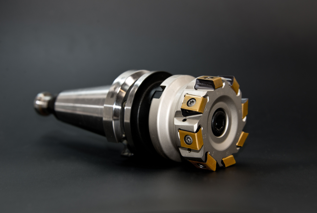
Indexable cutters hold replaceable inserts mechanically. They are well suited to face milling, heavy roughing, and larger diameters. Their economics improve when the body remains in service while inserts are indexed through several edges. The tradeoff is that the insert pocket, screw, and edge preparation limit how small and sharp the geometry can be.
For buyers, the useful comparison is cost per good part, not cutter price alone. Include insert edges, regrinding, setup time, predictable tool life, and the cost of a damaged workpiece.
Choosing Cutter Material
The cutter material must retain hardness at cutting temperature, resist abrasive wear, and survive the impact of repeated entry. No material leads on every measure.
High-speed steel is tough and relatively forgiving. It remains useful on manual machines, low-speed spindles, unstable setups, and short production runs. It can also be practical for large form tools where a solid-carbide body would be costly.
Cemented carbide is harder and more heat resistant, allowing much higher productive cutting speeds when the machine, holder, and workholding are rigid. The term covers many grades. Carbide grain size, binder content, edge preparation, and coating all influence the balance between wear resistance and toughness.
Coatings such as TiAlN, AlTiN, AlCrN, TiB2, ZrN, DLC, and diamond are chosen for particular heat, abrasion, and adhesion conditions. A coating cannot rescue poor geometry, excessive runout, packed chips, or an unstable setup.
Workpiece and operation | Practical starting direction | Why |
Aluminum slotting | 2-3 flute carbide end mill, polished flutes, large chip space | Reduces chip packing and built-up edge |
General steel profiling | 4-6 flute coated carbide end mill, variable pitch if chatter is likely | Balances core strength, edge count, and stability |
Stainless steel | Sharp positive geometry, controlled chip load, coating suited to heat and adhesion | Limits rubbing and work hardening |
Cast iron face milling | Indexable face mill with a wear-resistant carbide grade | Handles abrasive wear and broad surface coverage |
Hardened steel finishing | Rigid short-reach carbide tool with suitable high-temperature coating | Maintains edge shape under heat and hardness |
Manual or low-speed milling | HSS or tougher carbide with conservative parameters | Tolerates lower rigidity and impact more readily |
Tooth Count Is Really a Chip-Space Decision
More teeth can raise feed capacity because more edges share the work. They can also improve stability when several teeth remain engaged. But every added flute reduces chip space.
This is why a two- or three-flute end mill is common in aluminum and full-slot cutting, while a five- or six-flute tool may excel in stable side milling of steel. The high-flute tool is not inherently “more advanced.” It simply trades chip room for a stronger core and more cutting edges.
The same logic applies to indexable face mills. A coarse-pitch cutter leaves generous chip gullets and is often safer for unstable machines, interrupted surfaces, and difficult chip flow. A close-pitch cutter can produce more feed at the same feed per tooth, provided the spindle has enough power and the chips have somewhere to go.

Cutter Diameter, Reach, and Rigidity
Diameter affects much more than coverage. A larger face mill may reduce the number of passes, but it raises torque and may place more inserts in the cut. A smaller end mill reaches tighter corners, but its lower stiffness makes it more sensitive to runout and deflection.
Reach is often the hidden problem. Tool deflection rises quickly as overhang increases. Extending a short-flute cutter from the holder is usually worse than using a purpose-designed long-reach tool with a reinforced neck. Use only the reach required by the feature, keep the holder close to the work, and check for collisions in CAM before accepting extra stick-out.
Runout also matters. If one flute cuts more than the others, the loaded edge wears early and the remaining teeth do less work. Small-diameter tools are especially sensitive because a few micrometers of runout can represent a large share of the intended chip load.
Climb Milling vs Conventional Milling
In climb milling, the cutter rotation at the point of contact follows the feed direction. Chip thickness starts near its maximum and decreases toward the exit. On a rigid CNC machine with controlled backlash, climb milling is normally preferred because it reduces rubbing at entry and often gives better tool life and finish.
In conventional milling, the cutter works against the feed direction. The chip begins thin and grows toward the exit. The initial sliding can generate heat and accelerate wear, but conventional milling still has useful applications. It may be chosen when cutting through a hard scale or casting skin, when surface condition makes a heavy initial bite undesirable, or on older machines where backlash makes climb milling unsafe.
Face milling can include both cutting directions at different points of engagement when the cutter centerline passes through the work. The practical question is not merely which label applies, but how the cutter enters, where the thickest chip occurs, and whether the forces support the fixture and spindle.
A Practical Milling Cutter Selection Sequence
Start with the feature. A broad face points toward a face mill; a closed pocket or narrow slot points toward an end mill; an undercut may require a T-slot, dovetail, or other special cutter.
Next, check the workpiece material and condition. Abrasive cast iron, gummy aluminum, work-hardening stainless steel, and hardened tool steel need different edge shapes and grades. Include scale, interrupted sections, welds, and hardness variation rather than selecting from the nominal material name alone.
Then check the process limits: spindle speed and power, taper size, holder condition, fixture stiffness, coolant or air supply, programmed engagement, and required reach. A cutter selected for ideal catalog conditions can fail quickly when the real system has long overhang or inconsistent chip evacuation.
Finally, define how success will be measured. Roughing may prioritize material removal and predictable edge life. Finishing may prioritize size control, floor flatness, or surface texture. Production purchasing should track cost per good part and unplanned machine stops, not just the number of minutes before an insert is replaced.
Common Problems and What the Cutter Is Telling You
Symptom | Likely causes | First checks and corrections |
Chatter marks or loud vibration | Excessive overhang, weak fixture, too much engagement, resonant spindle speed | Shorten the tool, verify clamping, reduce engagement, test a different speed band or variable-pitch cutter |
Chips packed in a slot | Too many flutes, poor coolant direction, deep engagement, recutting | Use fewer flutes, improve air/coolant delivery, reduce step-down, open the toolpath |
One flute wears much faster | Holder or spindle runout, damaged collet, dirt on the shank | Clean the holder, measure runout near the cutting edge, replace worn clamping components |
Cutter pulls out of the holder | Oil on the shank, inadequate clamping, heavy helical load | Clean mating surfaces, use the correct torque, consider a higher-security holder |
Edge chipping | Impact, weak corner, excessive chip load, unstable entry | Add a corner radius, smooth entry, reduce peak load, select a tougher grade or edge preparation |
Rapid flank wear | Excessive speed, abrasive work material, rubbing, unsuitable grade | Reduce cutting speed, confirm real chip load, check coating and carbide grade |
Poor finish after tool change | Insert seating error, axial runout, pocket damage, inconsistent tool length | Clean pockets, torque correctly, inspect the cutter body, measure runout and tool length |
Change one variable at a time when possible. If speed, feed, depth, coolant, and tool geometry all change together, the next run may improve without revealing why.
What Buyers Should Ask Before Approving a Cutter
A useful supplier discussion goes beyond diameter, flute count, and coating color. Ask which operation and material the grade was designed for, whether the tool is intended for slotting or side milling, what runout and holder condition the recommended data assume, and how the supplier handles batch consistency.
For indexable tools, confirm the number of usable edges, insert availability, pocket protection, screw and spare-part availability, and whether alternate grades share the same seat. For solid tools, check regrinding limits and whether recoating preserves the original edge preparation.
Standard tools cover most jobs. A custom cutter becomes attractive when it combines operations, controls a difficult profile, reduces tool changes, or solves a reach problem that standard geometry handles poorly. The saving must be measured against lead time and replacement risk.

Conclusion
The right milling cutter is the one that creates the required feature reliably within the limits of the machine and setup. Cutter type establishes the basic capability. Material, construction, tooth count, diameter, reach, and cutting direction determine whether that capability becomes a stable production process.
Begin with the feature, then account for the workpiece, chip flow, rigidity, and success metric. That order prevents a common purchasing mistake: choosing an impressive cutter on paper that does not fit the actual cut.
HNCarbide supplies solid-carbide and application-specific milling tools for shops that need to improve tool life, chip control, or process stability. When a standard cutter is not producing repeatable results, a review of geometry and setup is usually more useful than another small feed-rate adjustment.




