 Skip to content
Cutting Forces in Precision Machining and How to Control Them
Table of Contents
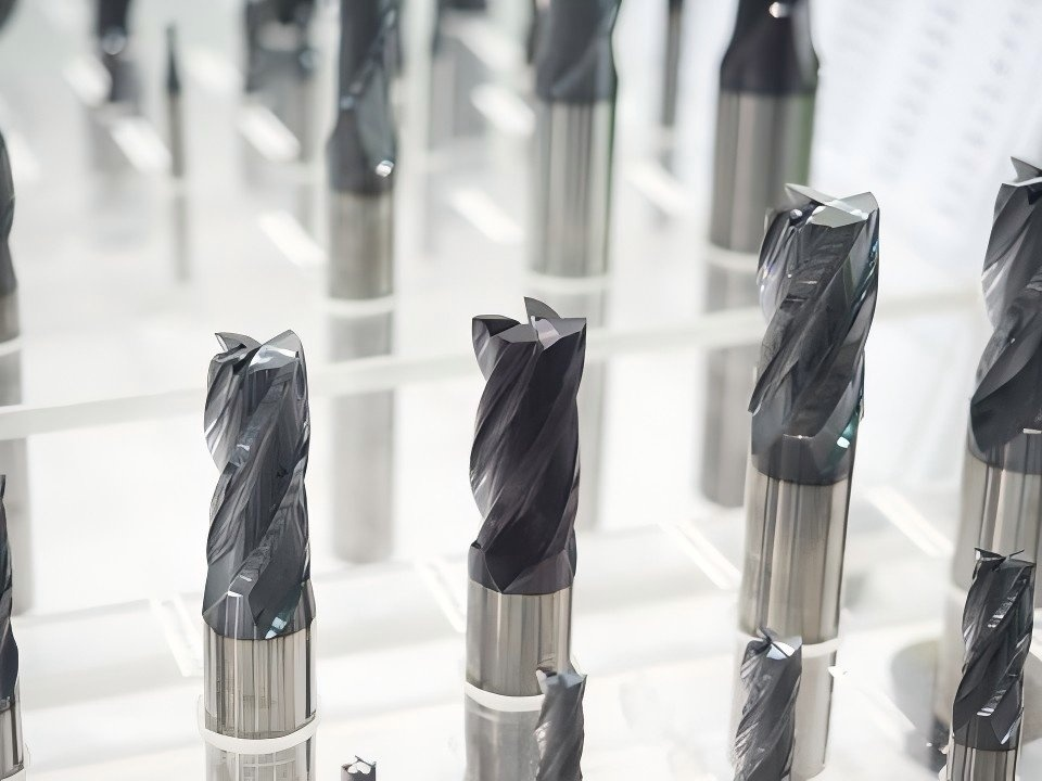
A finish pass can follow the programmed coordinates exactly and still leave a tapered wall. The machine has moved to the right position, but the cutting edge and the workpiece have moved under load. When the tool exits, they spring back. Measuring the unloaded part then reveals an error that was difficult to see during machining.
Cutting forces in precision machining matter because every tool, holder, fixture and component has finite stiffness. With solid carbide end mills, the choice of cutting length, flute geometry and toolpath directly affects how the assembly responds. The objective is to keep the load predictable and direct it through a sufficiently rigid setup. Simply choosing the lowest feed rate rarely achieves that. This guide focuses on end milling: how cutting forces develop, how they affect tolerances, and how to investigate them before changing cutters or cutting data.
Where cutting forces come from
A cutting edge separates material by deforming it into a chip. The material resists that deformation, while contact at the rake face and along the cutting edge adds friction. A worn flank can also rub against the newly machined surface. These interactions produce the load transmitted through the tool and workpiece.
The balance changes with the alloy, chip thickness, edge condition and lubrication. A sharp tool taking a well-formed chip behaves differently from a worn edge skimming a small finishing allowance. Diagnose the contact conditions in the actual cut before attributing a load change to material hardness alone.
Force also has a direction. In end milling, the local tangential and radial directions rotate with each tooth, while the machine’s X and Y axes remain fixed. A force recorded along one machine axis therefore does not represent the same local cutting-force component throughout the rotation. This matters when investigating wall deflection: identify the load acting across the wall, rather than treating every measured force as equally damaging.
Tangential force acts along the local cutting velocity and contributes to spindle torque. Radial force acts toward or away from the cutter axis and can bend the tool sideways. Axial force acts along the spindle axis, affecting floor loading and tool retention. Helix angle and the engaged cutting edge influence the distribution; a cutter that behaves well on a supported shoulder may load a thin floor unfavorably.
A side wall responds most strongly to the force normal to that wall. A thin pocket floor may be more sensitive to axial loading. Always identify the compliant feature before deciding which force component to reduce.
Why small loads can produce large dimensional errors
For an initial static estimate, displacement can be written as delta = F / k, where F is the force in the relevant direction and k is the effective stiffness in that direction. This is a simplified linear model, not a substitute for a dynamic machining analysis.
Suppose a setup has an effective lateral stiffness of 10 N per micrometre. A lateral force of 100 N would then produce 10 micrometres of displacement. These are illustrative values, not measurements from a particular machine. They show why an apparently modest cutting load can consume a tight tolerance.
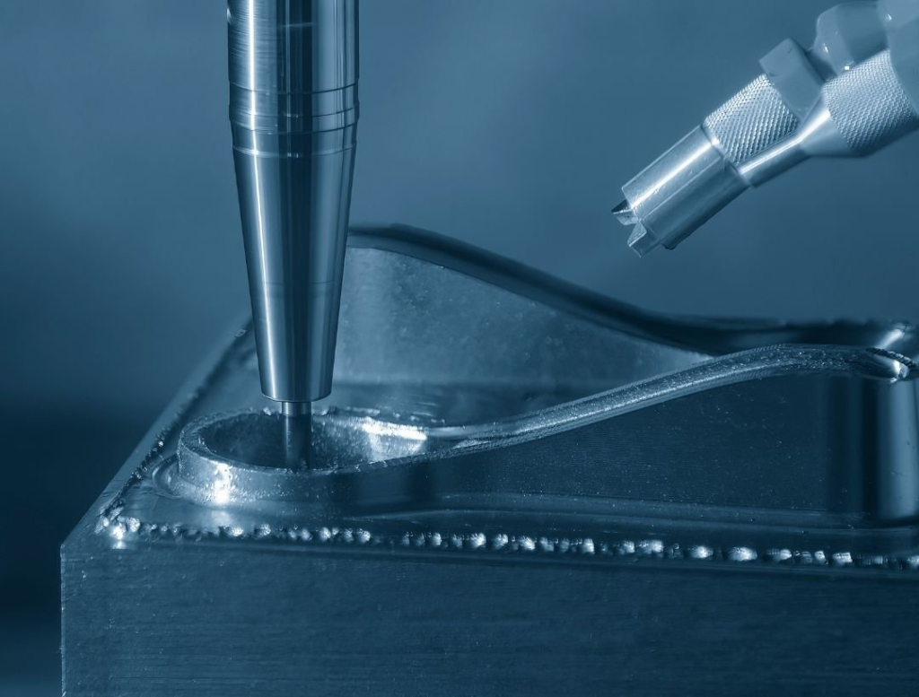
The complete load path matters. A rigid carbide end mill cannot compensate for a flexible wall or poor support beneath the workpiece. Extra tool projection makes the situation worse: in an ideal cantilever model, bending displacement grows with the cube of unsupported length. Real assemblies include flutes, joints and holder compliance, so the equation is useful for understanding sensitivity rather than predicting an exact shop-floor error.
A thin wall becomes less rigid as stock is removed. A finishing strategy that worked near the base can leave a different result near the unsupported top. Consider staged machining, balanced stock removal and support close to the cut. Check dimensions after unclamping as well; fixture distortion and residual stress release can produce errors that reducing cutting force alone will not solve.
Chatter introduces a separate problem. A steady load can create a repeatable offset, while unstable vibration can leave waves and damage the edge. Treating both as a simple tool compensation issue usually hides the cause. For a long-reach end mill, first review tool projection and holder rigidity, then consider how the toolpath directs the load into the workpiece. A repeatable dimensional offset and a fluctuating chatter pattern need different corrective actions.
What changes the cutting load
Material condition and edge geometry
Hardness is useful information, but it does not describe machinability on its own. Work hardening, ductility, microstructure and the tendency to adhere to the edge also influence chip formation. When comparing material batches, record the actual grade and condition instead of relying only on a broad description such as stainless steel.
A more positive cutting geometry often reduces deformation resistance, but the edge still needs enough strength for the application. Heavy interruptions and abrasive materials may require a more robust edge preparation. For light finishing, a sharp edge can help maintain chip formation at small allowances. For interrupted roughing, the edge must also withstand repeated entry impacts. Choose the edge preparation for the operation instead of assuming the sharpest available cutter will always last longest.
Do not confuse the microscopic cutting-edge radius with the tool’s corner radius. The first affects how the edge penetrates a thin chip; the second affects contact geometry, strength and force distribution over a much larger scale. Specifying a smaller radius without identifying which one can lead to the wrong tool change.
Engagement and chip thickness
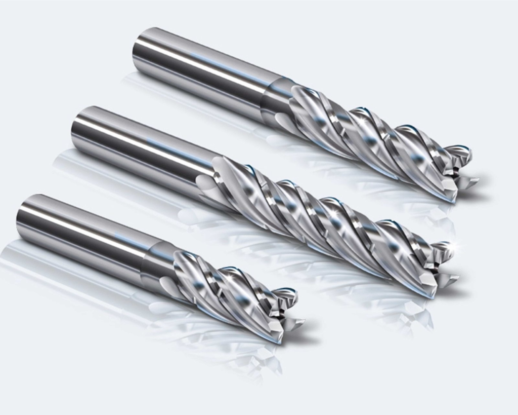
Increasing the amount of material engaged generally increases total load. In milling, however, axial depth, radial engagement and feed per tooth do different jobs. They change the length of edge in contact, the angular engagement and the chip thickness encountered by each tooth.
Reducing radial engagement can help control corner loads and permit a different combination of axial depth and feed. In a trochoidal pocketing path, an end mill takes repeated curved passes with limited radial engagement. This can allow more of the flute length to work while limiting the engaged arc, provided tool reach, workpiece stiffness and chip evacuation are suitable. Account for radial chip thinning when setting feed, and check that engagement remains controlled at entries and corners.
An extremely light feed is not automatically gentle on the tool. If the effective chip thickness becomes too small relative to the prepared edge, rubbing and ploughing become more significant. Consult the tool’s recommended chip-load range and account for runout, especially with small cutters. At low radial engagement, maximum chip thickness can be smaller than the programmed feed per tooth. Reducing feed again without accounting for that difference may increase rubbing during a finishing pass.
Speed and coolant
There is no universal speed curve in which cutting force first rises and then falls at a single critical speed. Temperature, adhesion, strain-rate effects and tool wear interact differently across materials and cutting conditions. A higher spindle speed may alter the force, but it also changes tool life and the machine’s dynamic response.
Coolant can affect friction, temperature and chip evacuation. Its benefit depends on reaching the relevant contact region and matching the tool-material combination. A force increase caused by recutting packed chips requires attention to evacuation; increasing coolant volume without improving delivery may leave the cause intact.
Estimate force and power without confusing the two
For end milling, start by separating feed per tooth from table feed. Table feed vf = n × z × fz, where n is spindle speed, z is the number of effective teeth and fz is feed per tooth. Material removal rate Q = ap × ae × vf / 1,000 when the engagement dimensions are in millimetres and table feed is in mm/min; Q is then in cm³/min.
Consider a 10 mm, four-flute end mill running at 8,000 rpm and a programmed feed per tooth of 0.04 mm. With 10 mm axial depth and 1 mm radial engagement, table feed is 1,280 mm/min and removal rate is 12.8 cm³/min. Assuming an effective specific cutting force kc of 1,800 N/mm², estimated net cutting power Pc = Q × kc / 60,000 is 0.384 kW. These assumed values illustrate the arithmetic only; they are not a cutting recommendation for an HNCarbide tool or a particular material.
Specific cutting force depends on the material and chip conditions. At low radial engagement, actual chip thickness differs from programmed feed per tooth, so the assumed kc requires particular care. Spindle input power also includes losses. Instantaneous chip thickness and the number of engaged teeth vary through the rotation, so average power cannot reveal tooth-level peak forces or the radial force that bends a wall.
At constant removal rate, reducing engagement requires another parameter to compensate. Raising spindle speed while holding feed per tooth constant also raises table feed. Neither change guarantees a lower damaging force component. Compare cycle time, load and dimensional results together.
A practical sequence for reducing cutting forces
Begin with the setup. Confirm tool projection, holder condition, runout and workpiece support. Then inspect the edge for wear, chipping or material buildup. Changing cutting data around a damaged edge produces a misleading trial.
Use the toolpath to control sudden engagement increases. An internal corner may load more of the cutter even when the programmed feed is unchanged. Smooth entries, an appropriate roughing strategy and consistent finishing stock can make the load more repeatable. When comparing paths, examine the highest-load regions as well as the average spindle reading.
Adjust one variable at a time during initial troubleshooting. Record the dimensional error at defined locations, surface appearance, cycle time and tool condition. Keep material batch and coolant conditions comparable. Once the dominant cause is understood, a structured multi-variable trial can refine the process.
Observed problem | Cause worth checking | First practical action |
Wall taper varies with cutting depth | Tool bending or changing wall stiffness | Shorten projection and review support and pass sequence |
Load spikes in internal corners | Sudden increase in radial engagement | Revise corner toolpath and local feed strategy |
Finish worsens after feed is reduced | Rubbing, chip thinning or edge buildup | Check actual chip thickness and inspect the edge |
Dimensions drift across a batch | Wear, thermal growth or material variation | Compare edge condition, temperature and load at matching cut locations |
Periodic marks and unstable sound | Chatter, runout or forced vibration | Check runout and rigidity, then test a suitable speed change |
The table is a starting point for diagnosis. More than one mechanism can be present, and a change that fixes one feature can increase the load on another. Validate the finished component rather than relying on a quieter cut alone.
Measure the signal that answers the production question
A machine’s spindle-load display is convenient for spotting repeatable changes in a comparable cut. It is an indirect signal and may miss a small lateral load that bends a slender feature. Filtering and drive response can also hide short peaks.
A dynamometer provides more detailed force information. Stationary systems measure through the mounted workpiece; rotating systems measure through the tool assembly. Their coordinate systems differ, and fixture mass and mounting affect the measurement dynamics. Choose the sensor after defining whether the objective is overload detection, tool comparison or analysis of individual tooth engagements.
Method | Useful application | Limitation to evaluate |
Spindle load or current trend | Routine monitoring of comparable production cuts | Indirect signal with limited directional information |
Stationary dynamometer | Controlled force comparisons and process development | Fixture integration and mounted-system dynamics |
Rotating dynamometer | Measurement through the rotating tool assembly | Added assembly length, interface compatibility and speed limits |
For a four-flute cutter running at 12,000 rpm, the tooth-passing frequency is 800 Hz. Resolving each engagement requires an acquisition system and usable mechanical bandwidth appropriate to that signal, with a suitable sampling margin and anti-alias filtering. A high advertised sampling rate alone does not establish usable measurement bandwidth.
Build a baseline from an acceptable cut with a known edge condition. Compare the same toolpath segments across parts; air cutting, entry and full engagement should not share one undifferentiated threshold. A rising signal can indicate wear, but it can also indicate extra stock, chip buildup or a changed material condition.
Closed-loop feed control can limit slow load changes when it is supported by the machine and validated for the process. Keep feed limits within the tool’s usable cutting range. Do not assume a feed override can suppress high-frequency chatter or react quickly enough to every tooth-level overload.
Use prediction to narrow trials
Start with a practical estimate, then calibrate it against the actual operation. Mechanistic models can represent the engaged edge and chip geometry; more detailed numerical models can investigate deformation and contact. Their usefulness depends on suitable inputs and validation. For an end mill, the model should represent the actual engaged edge, radial immersion and stock remaining along the path. A calculation based on a straight side cut can miss the higher engagement reached in an internal corner.
For a production decision, request the prediction error over the relevant material, tool and engagement range. A model that fits one test well may fail after a change in edge preparation or stock condition. A percentage improvement from a different study does not establish accuracy on your machine. The same requirement applies to data-driven models: the validation set must represent the intended production conditions.
Match the end mill to the feature and material
HNCarbide’s product range includes solid carbide square end mills, ball nose cutters, corner-radius tools and material-focused cutters for aluminum and stainless steel. These categories are useful starting points for a selection discussion, but the feature being machined determines which geometry makes sense.
End mill or application | Selection focus | Cutting force consideration |
Square end mill for shoulders and walls | Required corner form, short cutting length and adequate core rigidity | Lateral loading can produce wall taper; avoid unnecessary reach |
Corner-radius end mill for supported roughing | Radius allowed by the drawing and edge-strength requirement | A stronger corner does not guarantee lower force; engagement still matters |
Ball nose end mill for 3D finishing | Local contact position, effective diameter and tool orientation | Cutting speed approaches zero at the tip, making near-tip contact sensitive to rubbing |
Aluminum end mill for pockets and slots | Sharp geometry, flute space and reliable chip evacuation | Packed or recut chips can create erratic loads and edge buildup |
Stainless steel end mill for profiling | Suitable edge preparation, coating and stable chip formation | Avoid repeated rubbing and excessive engagement changes |
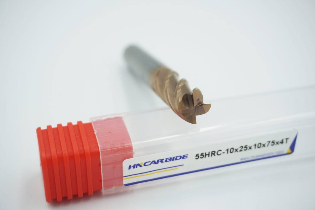
For a deep pocket, distinguish required reach from required flute length. A relieved-neck design can provide access without extending the fluted section over the entire reach, provided the neck and holder clear the part. Compare the actual dimensions and expected stiffness; the label “long reach” alone does not tell you how the cutter will behave.
Flute count also needs context. More flutes can support a higher table feed at the same feed per tooth, but they leave less chip space for a given diameter and flute design. A cutter chosen for light radial finishing is not automatically the right choice for full-width slotting. Use the supplier’s application data for the specific series, then validate the engagement on the machine.
Choose tooling around the tolerance requirement
When discussing a precision job with a tooling supplier, provide the material condition, critical feature, tolerance and available support. Include tool projection, holder interface, current cutting data and the location of the error. These details are more useful than asking for a cutter with the lowest possible cutting force.
Evaluate candidate tools under comparable conditions. A tool that reduces initial load but loses its edge quickly may increase size drift over the batch. Track acceptable parts per edge and dimensional consistency as well as cycle time. Agree on the wear or quality criterion that ends the trial before running it.

For an HNCarbide end mill inquiry, share the workpiece material and hardness, the required cutter diameter and reach, and whether the operation involves slotting, side milling or 3D finishing. Include the part drawing and current cutting conditions so the discussion can focus on a suitable square, ball nose, corner-radius or material-specific end mill. The right target is a stable process that holds tolerance through the planned tool life.





