 Skip to content
End Mill Flute Types and Count Explained
Table of Contents
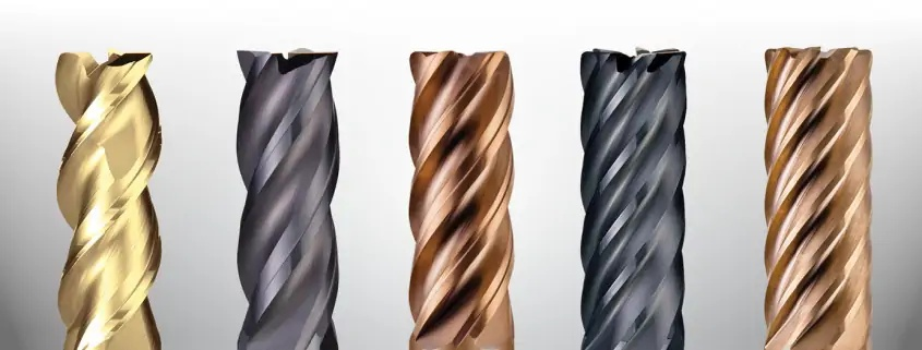
A pocket runs cleanly around its outer wall, then the cutter starts squealing in a corner. Chips collect at the bottom, the wall picks up scratches, and the next tool lasts no longer than the first. Changing from four flutes to three might help, but only if chip space was the limiting factor. A sudden increase in engagement, excessive overhang or poor coolant access can produce similar symptoms.
Choosing an end mill means matching its flute count and geometry to the cut it will actually make. This guide covers conventional solid end mills with one to six flutes, explains the main flute designs, and shows how to turn those details into a useful purchasing specification. The practical starting point is the workpiece material and toolpath, followed by chip clearance and setup rigidity.
What an end mill flute does
A flute is the groove beside a cutting edge. It provides space for a chip to form and escape as the edge passes through the workpiece. On a conventional end mill, the flute count normally matches the number of peripheral cutting edges.
Flute shape includes more than the visible spiral. Groove depth, rake geometry and the remaining core all affect how the tool behaves. Two cutters with the same diameter and flute count can therefore have quite different capabilities. A tool ground for aluminum should not be treated as interchangeable with a steel cutter simply because both have three flutes.
For comparable designs, adding flutes generally leaves less chip space and may permit a larger core. That tradeoff explains why a tool that performs well in light side milling can struggle in a full-width slot. The slot confines chips while placing more of the cutter in contact with material.
Keep end profile separate from flute geometry. Square, corner-radius and ball-nose describe the cutting end; helical, variable-helix and straight-flute describe other features. A corner-radius tool can also be a five-flute variable-helix cutter.
Choosing between one and six flutes
The following ranges are useful starting points for comparing tool families. They are not universal material limits, and six flutes is not the upper end of available tooling.
Flute count | Common starting application | What to check before choosing |
1 | Aluminum and plastics where chip clearance matters | Edge geometry, spindle suitability and achievable feed |
2 | Slots and pockets in aluminum or plastics | Material-specific design and permitted entry method |
3 | Aluminum roughing, pocketing and profiling | Chip exit route at full engagement |
4 | General steel milling and suitable stainless applications | Slotting limits, coating and available chip space |
5 | Steel or stainless side milling and dynamic roughing | Engagement control, rigidity and chatter behavior |
6 | Finishing or low-engagement milling with a suitable tool | Radial engagement, chip clearance and machine feed capacity |
One flute for room around the cutting edge
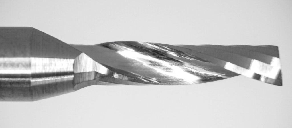
A single-flute end mill leaves a large open groove. This can be useful when machining soft aluminum or plastics that produce bulky chips. It also gives one cutting edge per revolution, so the required table feed for a chosen feed per tooth is lower than with a multi-flute tool at the same spindle speed.
Single-flute does not mean long-flute: flute count and cutting length are separate specifications. Nor does the open groove make blockage impossible. Chips can still weld to an edge, collect in a pocket or wrap around the tool. Single-flute designs can also be used for slotting and pocketing when the tool is rated for the operation.
Two flutes for enclosed cuts
A two-flute cutter is a sensible candidate when an enclosed cut makes chip removal difficult. In an aluminum slot, the useful question is whether the chips can leave before the edge reaches them again. A material-specific two-flute tool gives a practical starting point, but the groove depth and cutting parameters still determine how much chip volume it can handle.
For a small shop cutting both plastics and metal, it is tempting to standardize on one two-flute tool. Specify the material family instead. A sharp polished geometry for a thermoplastic may be a poor fit for repeated cuts in steel. The workpiece also needs to be identified more precisely than simply “plastic.” An unfilled thermoplastic and an abrasive fiber-filled grade can require different edge preparation and wear resistance.
Check entry capability independently. Flute count does not establish whether a cutter is center-cutting or suitable for plunging. Use the supplier’s ramping and plunging limits when programming the first move into a closed pocket.
Three flutes for aluminum pocketing and profiling
A three-flute aluminum cutter adds another cutting edge while retaining useful flute volume. It is worth comparing with a two-flute design when profiling an open wall or clearing a pocket with a toolpath that gives chips room to escape. The extra edge can support a higher table feed at the same programmed feed per tooth, provided the tool and setup can sustain it.
Consider an aluminum housing with an open pocket and a narrow internal slot. The three-flute tool may suit the pocket well, while the slot needs a different axial step or a separate cutter. Using one tool for both operations is possible only when its operating limits cover both. Three flutes do not automatically produce a better finish than two: runout, stock allowance and edge condition still need checking.
Four flutes for general metalworking
Four-flute tools cover many steel applications, but the number alone says little about the permissible cut. Compare the actual tool series, workpiece hardness and cutting length. A short general-purpose end mill and a long-reach finishing tool should not receive the same roughing program.
For a buyer, the useful question is whether the supplier supports the specific operation. Ask for full-slot data if the tool will cut slots. Side-milling data cannot establish full-slot capability. A cutter’s suitability for stainless steel also depends on its geometry and grade; the label “four flute” does not resolve those requirements.
Five flutes for productive side milling
Five-flute tools are used for more than finishing. Suitable designs can support dynamic roughing in steel and stainless steel, provided the toolpath maintains controlled engagement and the selected cutter is rated for the material.
For example, a steel bracket may have a tall outside wall that can be approached from an open edge. A suitable five-flute cutter can remove stock along that wall with a controlled radial step. If the path subsequently enters a narrow internal corner, review the local engagement before carrying the same feed through it. The cutter does not know that the CAM operation is labeled “dynamic”; it responds to the material actually surrounding its edges.
Six flutes for finishing and light radial cuts
A six-flute cutter may be productive along a wall with light radial engagement, yet unsuitable for taking that same axial depth in a full-width slot. “Two diameters deep” is incomplete information. For a 10 mm cutter, a 20 mm axial cut with a 0.5 mm radial step is a very different load from a 20 mm deep, 10 mm wide slot. These dimensions illustrate the distinction; they are not recommended cutting parameters.
For a finishing pass, also check that the stock allowance is reasonably consistent around the wall. An unexpectedly heavy patch can change the cutting load enough to spoil the finish, even when most of the path runs smoothly. More cutting edges are useful only when each edge can form and clear its chip.
Neither an odd flute count nor a higher count guarantees low vibration. Check the tool’s helix and pitch design, then evaluate it in the actual holder and fixture.
Flute geometry beyond the number of edges
These features can coexist on one cutter. A roughing tool may have helical flutes and variable pitch, for example. Treat them as specification choices rather than four mutually exclusive product categories.
Geometry | Main purpose | Selection caution |
Conventional helical flute | Progressive edge engagement and chip guidance | Helix direction and angle affect cutting forces |
Variable helix or variable pitch | Alter the repeating pattern of tooth engagement | Cannot compensate for an unstable setup |
Serrated or chipbreaker edge | Divide chips or modify roughing action | Confirm finish allowance and application limits |
Straight flute | Limit helix-induced axial pulling in suitable applications | Chip removal and entry capability need attention |
Conventional helical flutes
Helical cutting edges wrap around the tool axis. Their engagement progresses along the cutting length, rather than an entire straight edge entering at once. Helix angle changes the balance of forces; it should be evaluated alongside workholding and the feature being machined.
Do not assume that a spiral automatically breaks long chips into short pieces. Chipbreaker notches are a separate feature. Also avoid selecting a high helix purely because a thin wall needs a good finish: the resulting axial force must be acceptable to the fixture.
Variable helix and variable pitch
Variable helix changes the helix angle between cutting edges or along the tool, depending on the design. Variable pitch changes angular spacing between teeth. The two features are related in purpose but are not synonyms. They alter the repeating engagement pattern to help reduce chatter excitation.
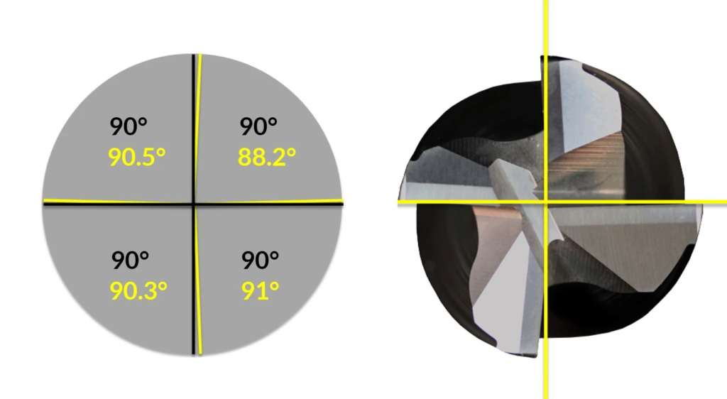
Before paying for a more specialized geometry, inspect the assembly. Record tool stickout, check the holder and collet, and verify how firmly the workpiece is supported. A geometry change can improve a stable process, but it cannot reliably rescue a loose connection.
Roughing serrations and chipbreakers
Roughing cutters may use serrations or discrete notches along the edge. These features help manage the chip and cutting action. Their profiles differ, so “roughing flute” is not a complete specification. Coarse and fine serration options must be matched to the supplier’s intended material and cutting conditions.
A serrated rougher may leave a wall texture that requires a separate finishing pass. Some staggered chipbreaker designs leave a less pronounced pattern, but the required surface finish still needs verification. Leave a deliberate allowance rather than discovering after roughing that there is insufficient stock to clean the wall.
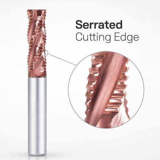
When comparing coarse and fine profiles, ask what surface the rougher is expected to leave and how much material the finishing tool will remove. A roughing trial should include that subsequent pass. Saving time in roughing has little value if uneven residual stock forces a slower finishing operation or causes local deflection.
Straight flutes for specific material problems
A straight flute runs parallel to the tool axis. It does not provide the same helix-induced lifting action as an upcut spiral. This makes straight-flute designs relevant where pulling on fibers or layers is undesirable, not merely for inexpensive soft-material machining.
Some two-straight-flute designs are intended for abrasive, fiber-filled plastics, but may permit only shallow ramping rather than plunge cutting. Check both material suitability and entry limits in the tool specification. Laminate construction, fiber direction and edge-quality requirements still matter.
Recalculate feed when the flute count changes
The basic relationship is:
Table feed = spindle speed × cutting teeth × feed per tooth
For an illustrative spindle speed of 8,000 rpm and a programmed feed per tooth of 0.04 mm, a three-flute cutter gives 960 mm/min. A six-flute cutter gives 1,920 mm/min. Keeping the original 960 mm/min with six teeth reduces the programmed feed per tooth to 0.02 mm.
This arithmetic does not authorize doubling the feed. Confirm the new tool’s recommended chip load and engagement first. The machine must also achieve the feed through the programmed path. A short segment or tight corner may prevent the commanded value from being reached.
At low radial engagement, actual chip thickness can be lower than programmed feed per tooth. Apply the tool supplier’s chip-thinning guidance and check whether its recommended feed already includes compensation. Increasing it twice can overload the edge.
Diagnose the cut before ordering another tool
Use the failure location to narrow the investigation. A problem that appears only inside corners suggests a different starting point from deterioration along an open straight wall. The checks below identify possibilities, not definitive diagnoses.
Observed problem | Possible contributor | First useful check |
Chips pack in a slot | Restricted chip space or poor evacuation | Compare slotting limits and inspect coolant access |
Chatter appears in corners | Sudden increase in engagement | Review the toolpath and local cutting load |
Wall scratches follow loose chips | Chip recutting | Inspect the chip exit route and pocket cleaning |
Finish worsens after adding flutes | Changed chip load, runout or a damaged edge | Recalculate feed per tooth and inspect the tool |
Wall taper persists | Deflection or insufficient support | Check overhang, tool diameter and workholding |
Composite edges fray | Unsuitable cutting action for the laminate | Review material-specific straight or compression geometry |
Change one controllable factor at a time during a trial. Record the exact tool code, material condition and operation, then compare wall quality and edge wear after the same cutting distance. A faster first part is not enough evidence to standardize a production tool.

What to include in a tooling enquiry
Send the supplier the alloy and hardness, feature drawing, cutter diameter and required reach. Include radial and axial engagement, the entry method, spindle limits and coolant arrangement. If the current process fails, identify where it fails and supply a clear photograph of the worn edge.
Request separate recommendations for roughing and finishing when the operations place different demands on the tool. Ask for allowable slotting depth, recommended chip load and any restrictions on ramping. For repeat orders, preserve the full tool designation rather than recording only “10 mm four flute.”
Choose the lowest or highest flute count only when the application supports it. Chip space, engagement and edge geometry determine which tool belongs in the holder. When discussing a cutter with HNCarbide, provide those operating details so the enquiry can focus on a suitable geometry and a practical trial plan.





