
Cutting Speed, Feed Rate, and Depth of Cut for End Mills: A Practical CNC Guide
Table of Contents
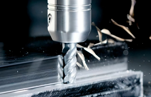
Every CNC shop talks about speed and feed, but stable end milling usually depends on three settings working together: cutting speed, feed per tooth, and depth of cut. Change one without thinking about the other two and the process can move from clean cutting to heat, rubbing, chatter, poor finish, or chipped end mill edges.
That is why two machinists can use the same solid carbide end mill on the same machine and get very different results. One job runs quietly, holds size, and gets predictable tool life. Another burns corners, leaves heavy feed marks, packs chips in the flutes, or overloads the spindle. The difference is often not the tool brand or the CNC program alone. It is the way cutting speed, chip load, axial depth, radial engagement, tool overhang, coolant, and workpiece material were balanced.
This guide explains the three essential cutting parameters in plain shop-floor terms, then shows how to choose them for roughing, semi-finishing, and finishing. The goal is not to replace toolmaker data. It is to help engineers, programmers, and production teams understand the logic behind those data tables so parameter changes become controlled decisions instead of trial-and-error guesses.
What Are the Three Main Cutting Parameters?
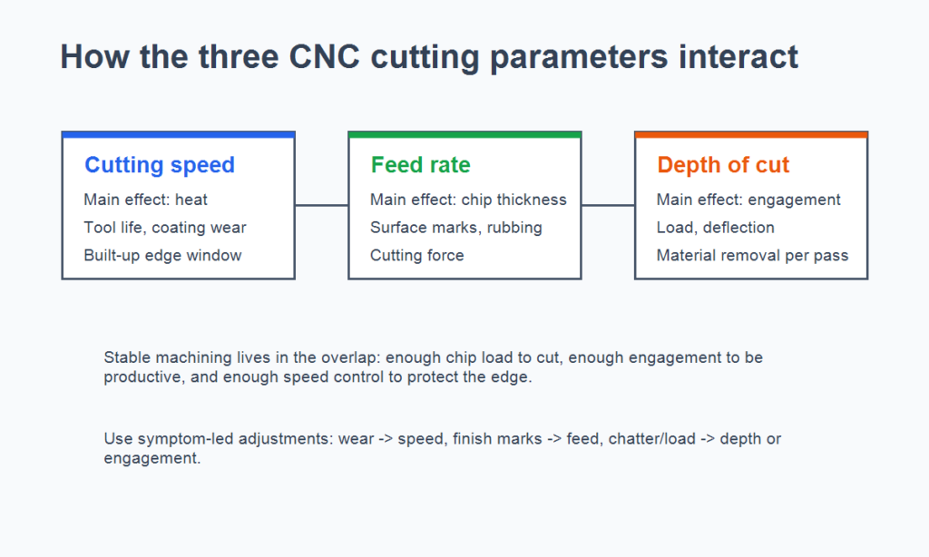
Cutting speed, feed rate, and depth of cut describe three different parts of the same cutting action. Cutting speed controls how fast the cutting edge moves across the material surface. Feed controls how much material the edge takes as it advances. Depth of cut controls how much stock is engaged in one pass.
Together, they decide chip thickness, heat generation, cutting force, tool deflection, spindle load, and surface texture. Treating them as separate knobs is a common setup mistake. In real machining, each one changes the safe operating window of the others.
Parameter | Common symbol | What it controls most directly | Typical unit |
Cutting speed | Vc or SFM | Heat, tool wear rate, coating performance, built-up edge tendency | m/min or ft/min |
Feed rate / chip load | f, fz, or feed per rev | Chip thickness, surface roughness, cutting force, rubbing risk | mm/rev, mm/tooth, in/rev, in/tooth |
Depth of cut | ap, ae in milling | Material removal per pass, tool engagement, load, deflection | mm or inch |
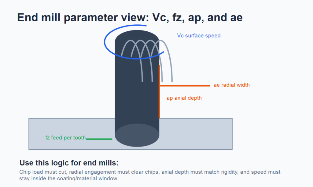
For end mills, programmers usually think in feed per tooth, or chip load.
The feedrate shown on the control is calculated from spindle speed, flute count, and chip load:
Feedrate = spindle rpm x number of teeth x feed per tooth
For cutting speed with an end mill:
Vc = pi x D x n / 1000
Where Vc is cutting speed in m/min, D is diameter in mm, and n is spindle speed in rpm. The same rpm can create very different cutting speeds when the tool or workpiece diameter changes, which is why copying rpm from another job without checking diameter is risky.
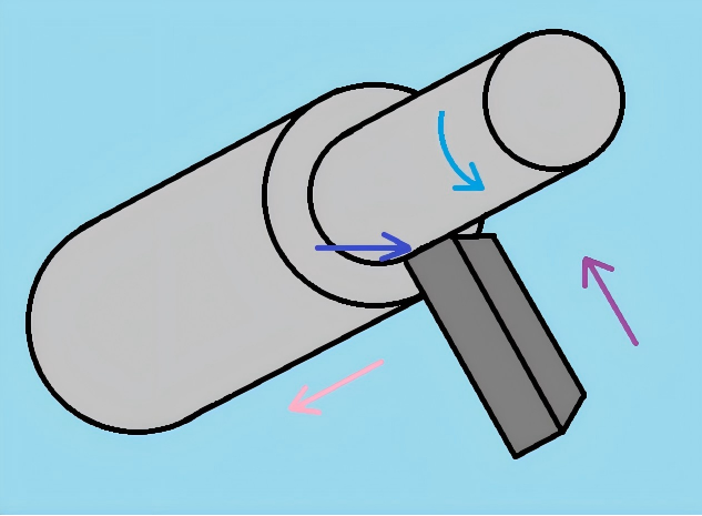
Cutting Speed: The Strongest Driver of Tool Life
Cutting speed has the largest influence on carbide tool life because it strongly affects cutting temperature. A higher surface speed means the edge travels farther against the material in the same time. That can improve productivity and sometimes improve chip flow, but it also raises heat at the cutting zone.
When cutting speed is too high for the carbide grade, coating, work material, flute geometry, or coolant condition, wear often accelerates quickly. The shop-floor signs are familiar: corner wear grows faster than expected, the cutting edge loses its coating, the end mill starts squealing in the cut, or the part suddenly shows chatter and poor finish after a few acceptable pieces.
Running too slow has its own problems. In steels, stainless steels, and other ductile materials, low cutting speed can encourage built-up edge. The tool rubs and smears instead of shearing cleanly. In work-hardening materials, a speed that is too low can also let the edge dwell and rub, leaving a hardened surface for the next pass.
The useful rule is simple: raise cutting speed only after the chip load and depth of cut are stable. Speed can reduce cycle time, but it is rarely the cheapest way to remove more metal if it cuts tool life in half.
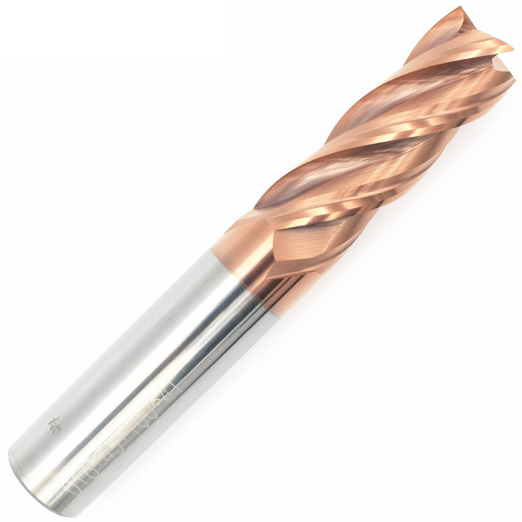
Feed Rate: The Main Control for Chip Thickness and Surface Finish
Feed is the parameter most directly tied to chip thickness and surface finish. In end milling, feed per tooth decides how much material each flute removes. The programmed feedrate can look reasonable on the control, but if flute count, rpm, or radial chip thinning are ignored, the actual cutting edge may be overloaded or barely cutting.
If feed is too high, cutting force rises, chip thickness increases, and surface roughness becomes more visible. On a weak setup, aggressive feed can push the end mill into deflection, chatter, corner chipping, or wall taper. On a finishing pass, even a small feed increase can change the measured roughness more than the operator expects.
If feed is too low, the tool may stop cutting properly. Carbide edges are not infinitely sharp; they need enough chip thickness to shear the material. When the programmed feed falls below the practical minimum chip thickness, the edge rubs, polishes, and heats the work surface. This is why “feed slower for a better finish” is not always true. Below a certain point, slower feed can make the finish worse and shorten tool life.
Feed should be selected with the end mill geometry in mind. A 2-flute aluminum end mill, a 4-flute steel end mill, a roughing end mill, and a long-reach finishing end mill all want different chip loads. The same feed number can be safe in one tool and abusive in another.
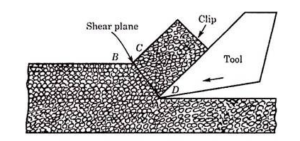
Depth of Cut: The Main Load Lever
For end mills, depth of cut needs two values: axial depth of cut, ap, and radial width of cut, ae. Axial depth describes how much of the flute length is engaged. Radial width describes how much of the cutter diameter is engaged. A full slot, a light side-milling pass, and a high-efficiency milling path can use the same tool diameter but create completely different loads.
Depth of cut usually has less direct effect on tool life than cutting speed, but it has a major effect on cutting load and deflection. A deeper axial cut can be efficient when the machine, holder, tool overhang, flute length, workholding, and part geometry are rigid enough. In roughing, increasing axial engagement and controlling radial engagement is often a better productivity move than simply raising rpm.
But depth of cut is not “free.” Too much radial engagement can overload the spindle, trap chips, create vibration, pull the wall out of tolerance, or break the end mill. Too little engagement can also be inefficient. Many shallow passes increase tool entry and exit events, add air cutting, and may keep the edge rubbing near the previous work-hardened surface.
For roughing, the best depth of cut is often the largest stable value that the setup can support. For finishing, the best value is usually a controlled, consistent allowance that lets the tool cut cleanly without deflection.
How the Three Parameters Affect Each Other
The most useful priority order for tool life is:
Cutting speed has the strongest effect, feed comes next, and depth of cut usually has the smallest direct effect.
That order does not mean depth of cut is unimportant. It means that if an end mill is wearing too fast because of heat, reducing surface speed often has a larger effect than making the pass slightly shallower. If the wall or floor finish is rough, changing feed per tooth, radial engagement, runout, or finishing allowance may do more than changing speed. If the machine is vibrating or overloaded, reducing radial engagement or shortening tool overhang is often the quickest way to stabilize the cut.
The three settings should be adjusted based on the problem you are solving:
Machining symptom | Parameter to check first | Why it matters |
Rapid flank wear or crater wear | Cutting speed | Heat may be above the grade/coating window |
Heavy feed marks on finishing | Feed per tooth, runout, corner radius, and finishing allowance | Feed often dominates roughness pattern |
Rubbing, smearing, or work hardening | Feed rate and cutting speed | Chip thickness may be too low, or speed may be outside the stable cutting window |
Chatter under load | Depth of cut, radial engagement, feed | Cutting force may exceed setup rigidity |
End mill corner chipping | Feed, radial engagement, tool overhang | Impact load or deflection may be too high for the tool geometry |
Chips packing in flutes | Feed, radial engagement, flute count, coolant/air blast | Chips may not have enough room to evacuate cleanly |
This is where many parameter problems start. A programmer raises rpm to cut faster, but feed per tooth is not increased correctly. The tool starts rubbing because chip thickness is too small. Another shop reduces depth of cut too much to “protect” the tool, then needs several extra passes, more interruptions, and longer cycle time. The process looks safer on paper but costs more per part.
Roughing Strategy: Remove Metal Without Burning the Edge
Roughing is about material removal rate, but the right strategy is not simply maximum speed.
A practical roughing sequence is:
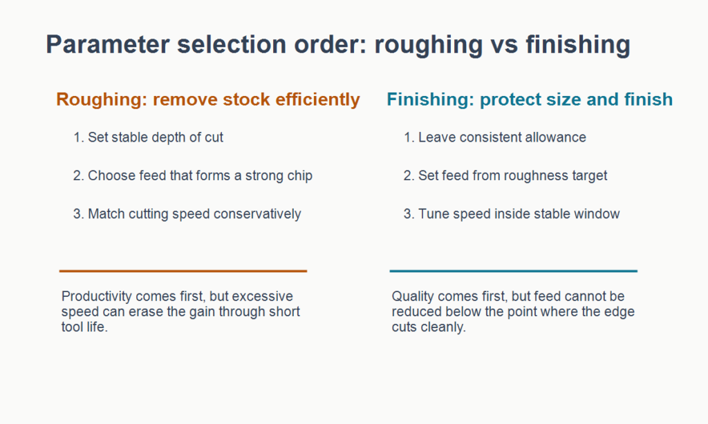
- Choose the largest stable depth of cut or engagement the setup can support.
- Select a feed per tooth that forms a real chip without overloading the flutes.
- Set cutting speed conservatively within the carbide grade, coating, and material range.
This order works because end mill roughing usually benefits from using the available flute length and machine power without burying the cutter. If rigidity is good, a deeper axial pass with controlled radial engagement may be more economical than several shallow conventional passes. It reduces repeated entries, shortens cycle time, and may keep cutting load more stable.
In steel roughing with solid carbide end mills, for example, a moderate surface speed with a stable chip load often gives better cost per part than an aggressive surface speed with fragile tool life. In aluminum, high speed can work well only when flute geometry and chip evacuation are right. In stainless steel, feed must stay high enough to avoid rubbing, while speed must be managed carefully because heat does not leave the cutting zone easily.
Finishing Strategy: Control the Last Pass
Finishing has a different target. The final pass must hold size, surface roughness, edge condition, and visual quality.
The usual sequence is:
- Leave a consistent finishing allowance.
- Set feed based on the required roughness, runout, corner radius, and end mill geometry.
- Fine-tune cutting speed to improve cutting action without causing fast wear or thermal growth.
Small depth of cut is normal in finishing, but it should still be large enough for the edge to cut cleanly. If the allowance is inconsistent, the tool alternates between rubbing and loading. That is a common cause of scattered size, visible marks, and unpredictable finish.
For end milling, finishing feed must be balanced with tool runout, flute count, radial engagement, stickout, and surface speed. A catalog finish value is meaningless if the holder runout makes one flute carry most of the cut or if the finishing allowance varies from wall to wall.
Material Changes the Starting Point
No universal parameter set works across common shop materials. Steel, alloy steel, stainless steel, cast iron, aluminum, and titanium behave differently under the cutting edge. A good parameter plan starts with the work material and then narrows the range based on tool grade and setup rigidity.
Workpiece material | Cutting-speed focus | Feed/depth-of-cut focus | Common caution |
Medium-carbon steel | Balance productivity and tool temperature | Use enough feed to avoid rubbing; rough with stable depth | Built-up edge at low speed, fast wear at excessive speed |
Alloy steel / 42CrMo-type materials | Manage heat and hardness variation | Avoid overload in hard spots; keep chip load consistent | Corner chipping if feed and engagement exceed tool toughness |
Stainless steel | Avoid rubbing and work hardening | Maintain chip thickness; use stable coolant and sharp geometry | Low feed can damage the surface for the next pass |
Cast iron | Control abrasion and edge wear | Use rigid setup and suitable carbide grade | Dust, abrasive wear, and edge breakdown |
Aluminum alloy | Use sharp tools and high chip evacuation | Feed can be high if chips clear cleanly | Built-up edge and chip welding if geometry/coolant is wrong |
Titanium alloy | Keep heat under control and avoid rubbing | Conservative speed, positive geometry, reliable chip load | Heat stays near the edge; tool life can drop quickly |
This is also why tooling buyers should look beyond price per end mill. The right carbide grade, coating, flute geometry, helix angle, corner protection, and edge preparation can widen the usable parameter window. A cheaper end mill that only runs safely in a narrow range may cost more in downtime and scrap.
Common Parameter Mistakes
One common mistake is assuming higher spindle speed always means faster machining. Spindle speed is only one part of the equation. If surface speed goes beyond what the tool and material can handle, tool wear accelerates and the job becomes more expensive.
Another mistake is slowing the feed too far to improve finish. A moderate feed reduction can help, but a feed that is too light may stop the edge from cutting. The result is rubbing, heat, work hardening, and a finish that still does not meet the drawing.
A third mistake is making every cut shallow in the name of safety. Shallow passes can be useful for weak parts, thin walls, or unstable fixturing. But in rigid roughing, too many shallow passes waste cycle time and increase entry/exit shocks.
The last mistake is copying parameters across materials. A setup that works in 45 steel may fail in stainless steel. A speed that is comfortable in aluminum may destroy a carbide edge in titanium. A flute geometry that clears aluminum chips well may not have the edge strength needed for harder alloy steel. Good shops build starting points by material family, operation type, tool diameter, flute count, and stickout, then adjust with measured evidence from the machine.
Matching Parameters With Tool Selection
Cutting parameters are never independent from end mill selection. Flute count, helix angle, core diameter, corner radius, edge preparation, carbide grade, coating, holder rigidity, and coolant delivery all affect the safe range.
For heavy roughing, choose an end mill with enough core strength, flute space, and corner protection for the material. Use a stable axial depth, controlled radial engagement, and a feed per tooth that makes a chip without packing the flutes. Keep cutting speed in a conservative range until tool life is proven.
For high-quality finishing, choose a geometry that supports the material and the wall/floor requirement. Feed should be set from the surface requirement, tool diameter, runout, and finishing allowance, not from habit. A small corner radius may strengthen the edge, but only if the drawing allows it.
For thin-wall parts or vibration-sensitive setups, reduce engagement and cutting force before chasing speed. Sometimes a lower depth of cut, lighter radial engagement, sharper tool, and adjusted tool path do more for stability than a simple rpm change.
A Practical Setup Checklist
Before releasing a new CNC program into production, check the cutting parameters in a structured way:
Setup question | Why it matters |
What is the actual cutting speed at the tool or workpiece diameter? | Prevents accidental overspeed from copied rpm values |
Is chip load high enough to cut instead of rub? | Protects tool life and avoids work hardening |
Is depth of cut matched to machine, holder, tool overhang, and workholding rigidity? | Reduces chatter, deflection, wall taper, and tool breakage |
Do flute count and flute space match the chip load and material? | Improves chip evacuation and edge stability |
Is the finishing allowance consistent? | Helps final pass hold size and surface roughness |
Are coolant and chip evacuation suitable for the material? | Prevents recutting, welding, and thermal damage |
Is tool life measured by parts, minutes, wear land, or finish limit? | Makes improvement work measurable instead of subjective |
Parameter setting becomes much easier when the team agrees on what failure looks like. Is the process limited by tool wear, surface roughness, chatter, cycle time, burrs, or dimensional drift? Each problem points to a different first adjustment.

Conclusion
Cutting speed, feed rate, and depth of cut are the foundation of CNC machining performance. Cutting speed drives heat and tool life. Feed controls chip thickness and surface pattern. Depth of cut controls engagement and load. The best result comes from balancing all three around the work material, tool geometry, machine rigidity, and production goal.
For roughing, use stable depth and feed before pushing speed. For finishing, control allowance and feed first, then tune speed inside a reliable tool-life window. This approach reduces blind trial cuts, protects carbide edges, improves part quality, and gives production teams a clearer path to lower cost per part.
HNCarbide develops carbide end mills and cutting tools for steel, cast iron, stainless steel, aluminum, and other demanding machining conditions. If your team is reviewing flute geometry, coating, tool diameter, or parameter windows for an end milling job, HNCarbide can help match the tool choice with a practical cutting strategy.




