
How Edge Condition Controls Carbide Insert Tool Life
Table of Contents
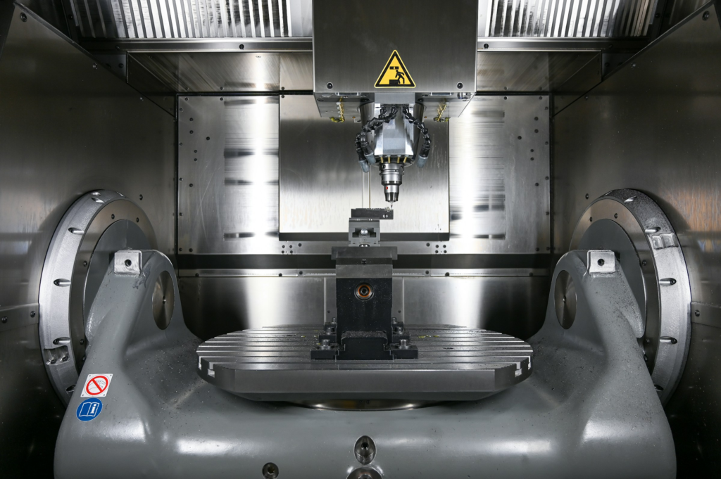
In many CNC shops, tool life is judged at the moment something obvious happens: the insert chips, the finish turns rough, the spindle load jumps, or the part dimension starts to drift. By that point, the cutting edge has usually been telling a quieter story for a while.
The real tool-life decision often happens earlier, as the edge changes from clean shearing to heavy rubbing. A fresh carbide insert does not stay “sharp” forever. Its edge radius grows, the contact area increases, heat builds faster, and the tool moves from a stable wear zone into a fast-consumption zone. Understanding that transition helps production teams avoid two expensive habits: changing inserts too early, and pushing worn inserts until they damage parts.
This guide looks at the cutting edge as a process variable. The goal is practical: know what a sharp edge gives you, recognize what a dull edge costs you, and set tool-change rules before the insert reaches the point where wear becomes hard to control.
Why a Sharp Edge Is the Tool-Life “Stable Window”
A sharp insert does not simply feel better in the cut. It changes the mechanics of chip formation.
When the edge radius is small and the geometry is still intact, the tool enters the material with less ploughing. More of the cutting energy goes into shearing the chip, and less is wasted in sliding friction between the tool, chip, and finished surface. That is why a new or properly prepared insert often produces a cleaner sound, lower cutting force, steadier spindle load, and better surface finish.
For tool life, this matters in three ways.
First, the cutting zone runs cooler. Carbide retains hot hardness better than many tool materials, but it is not immune to heat. Excessive temperature softens the binder phase, speeds chemical wear, and can weaken the coating/substrate system. A sharper edge keeps the process in a lower-temperature range for longer.
Second, force fluctuation is smaller. A stable edge cuts rather than hammers. Lower cutting force reduces mechanical stress at the cutting edge, especially in interrupted cuts such as milling, grooving, cross holes, cast skins, keyways, or turning over interrupted surfaces.
Third, the workpiece surface is less likely to be damaged by rubbing. A sharp edge is less likely to smear the material, work-harden the surface, or leave a raised burr that punishes the next pass. In stainless steel, nickel alloys, and some steels, this point is easy to miss. A dull edge can create a harder skin, then the next cut has to machine that skin, which accelerates wear again.
The best tool life is not produced by an infinitely sharp, fragile edge. It is produced by an edge that is sharp enough to cut cleanly and prepared well enough to survive the application.
Sharp Does Not Always Mean Needle-Sharp
One common misunderstanding is that a sharper insert is always better. In real carbide tooling, a controlled edge hone or edge radius is often intentional. A microscopically perfect knife edge may cut freely, but it may also chip quickly under CNC loads.
Edge preparation is the compromise between low cutting force and edge strength. Finishing aluminum may need a very free-cutting geometry with a small hone and polished rake face. Heavy roughing in steel may need a stronger honed edge that can handle load and interrupted contact. Stainless steel and high-temperature alloys often need a balance: enough sharpness to reduce rubbing, but enough edge support to resist notching, adhesion, and thermal stress.
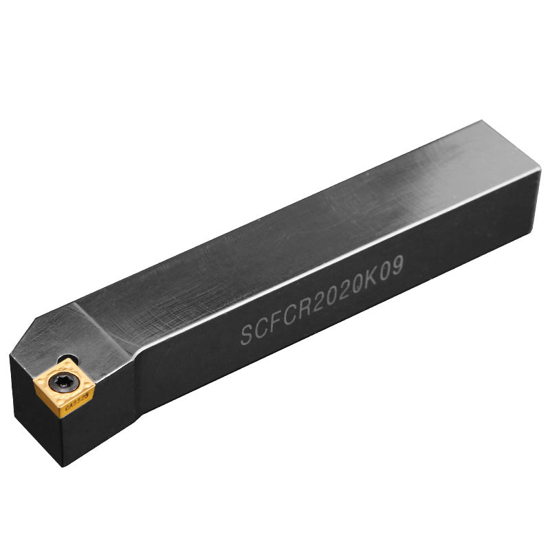
For buyers, this is why two inserts with the same ISO shape and nominal grade can behave differently. The coating, substrate, chipbreaker, edge hone, and consistency of preparation all affect how quickly the edge leaves the stable zone.
Edge condition | What it does well | Main risk | Typical fit |
Very sharp, light hone | Low force, clean finish, lower heat at light cuts | Micro-chipping under heavy or interrupted load | Aluminum finishing, small depths of cut, light finishing passes |
Controlled honed edge | Balanced cutting action and edge strength | May rub if feed is too light for the edge radius | General turning and milling in steels and stainless steels |
Strong honed or chamfered edge | Resists impact and edge breakage | Higher force and heat if used in light finishing | Roughing, interrupted cuts, tougher work materials |
Worn/dull edge | No real advantage except delaying a tool change | Heat, force, finish problems, sudden failure | Should be removed before the rapid-wear stage |
What Changes When the Edge Becomes Dull
As the insert wears, the edge radius grows and the cutting geometry changes. The tool begins to push more material ahead of the edge before the chip forms. The rake face sees more chip friction, and the flank face rubs harder against the newly machined surface.
This is the point where tool life starts to deteriorate faster than output.
Temperature rises faster
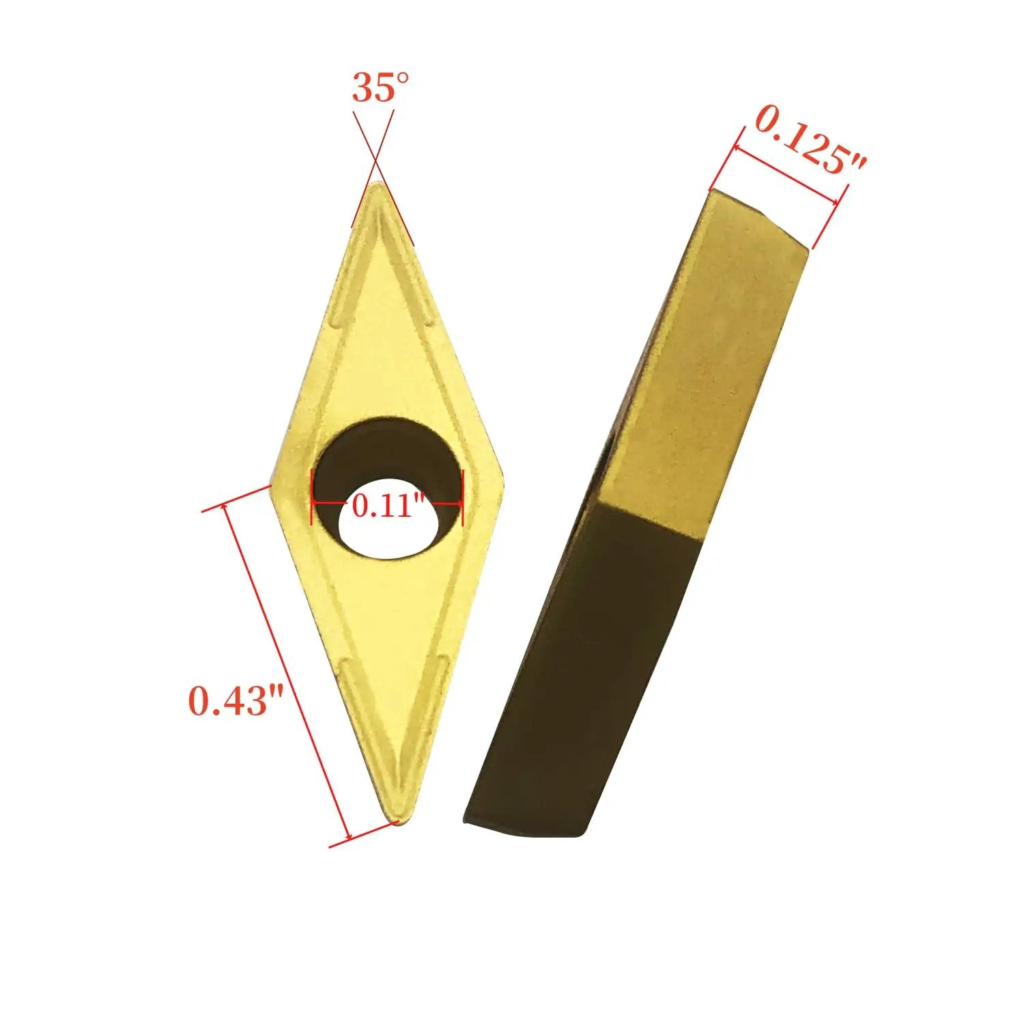
A dull edge has more contact area. More contact means more friction. More friction means more heat, and heat does not increase wear in a neat straight line. Once temperature gets high enough, coating oxidation, diffusion wear, adhesion, and carbide substrate weakening can all accelerate together.
This is why a tool may appear acceptable for most of its run, then degrade quickly near the end. The process has crossed a thermal and mechanical threshold.
Cutting force climbs
A dull edge acts more like a small rounded wedge pressing into the workpiece. Cutting force may rise substantially, and the increase is often seen first in feed force, spindle load, sound, or vibration. In stable continuous turning, the rise may be gradual. In milling or interrupted turning, the extra force can show up as edge frittering, chipping, or sudden insert failure.
Surface quality becomes part of the wear problem
Once the edge starts rubbing instead of cutting cleanly, the part surface becomes less predictable. Roughness increases, burrs become stronger, and dimensions drift as the tool wears. In work-hardening materials, the worn edge may leave a harder surface layer. The next pass then cuts a worse material condition than the previous pass, which feeds more wear back into the tool.
That feedback loop is one reason “just run the insert a little longer” can become more expensive than a planned tool change.
The Three Stages of Cutting Edge Tool Life
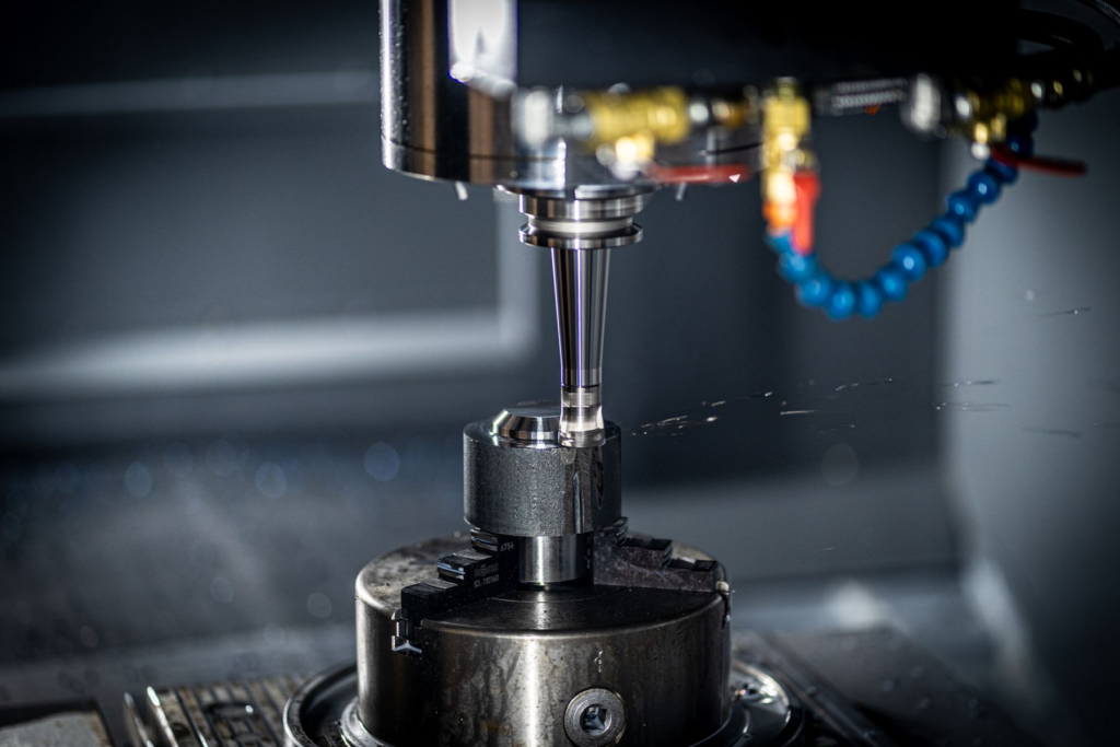
Tool life is often drawn as a wear curve. On the shop floor, it is better understood as three working zones.
Tool-life stage | Edge condition | Wear rate | Practical strategy |
Initial wear | Edge settles in; tiny defects or high spots polish away | Moderate at the start, usually short-lived | Confirm the insert is not chipping immediately; avoid judging life too early |
Normal wear | Edge remains stable, cutting action is predictable | Slow and manageable | Use this zone as the main production window |
Rapid wear | Edge is noticeably dull; rubbing and heat dominate | Fast, often nonlinear | Replace before this zone damages parts, holders, or machine stability |
Initial wear is not always bad. A new edge may polish slightly during the first few parts, especially when a honed insert is running in a stable cut. The problem is early chipping or flaking, which suggests the edge, grade, coating, or setup is wrong for the job.
Normal wear is the best economic zone. The insert is not new, but it is still cutting predictably. This is where production teams should collect part counts, cutting time, spindle load, surface finish readings, and wear observations.
Rapid wear is the zone to avoid. Once an edge enters this stage, every extra part may cost more in finish risk, dimensional correction, rework, and sudden failure than it saves in insert cost.
The Wear Modes That Turn a Sharp Edge Into a Dull One
Different wear patterns dull the edge in different ways. Knowing which pattern is dominant helps you adjust the process instead of guessing.
Flank wear: the normal tool-life yardstick
Flank wear develops on the clearance face where the tool rubs against the newly machined surface. It usually appears as a wear land behind the cutting edge. In many cutting-tool standards and shop-floor rules, flank wear width, often written as VB, is the primary tool-life criterion.
Uniform flank wear is usually the most predictable failure mode. If the wear land grows slowly and evenly, the process can be managed with a part-count or cutting-time tool-change rule. If it grows quickly, the first checks are cutting speed, grade hardness, coolant delivery, workpiece abrasiveness, and whether the feed is too light for the edge prep.
Crater wear: heat and chip flow on the rake face
Crater wear forms on the rake face, where the chip slides across the insert under high temperature and pressure. It is common in higher-speed steel machining and in operations where chip-tool contact is severe.
The danger is that crater wear weakens the edge from behind. The cutting edge may still look usable from the flank side, but the support under the edge is being eaten away. As the crater deepens, chipping becomes more likely.
Chipping, flaking, and breakage: when dullness becomes failure
Chipping is not gradual dulling. It is local fracture. It can happen early if the edge is too sharp or the setup is unstable, but it often becomes more likely after wear has already reduced edge strength.
Common triggers include interrupted cutting, excessive feed, long overhang, poor clamping, runout, chip recutting, thermal cracking, or an insert grade that is too hard and brittle for the operation. Once chipping starts, tool life becomes difficult to predict. A small missing edge can quickly become a larger break, especially in milling.
Wear form | Where it appears | What it usually means | First corrective move |
Uniform flank wear | Clearance face behind the edge | Normal abrasion and rubbing | Track VB, reduce speed if wear is too fast, confirm coolant and grade |
Rapid flank wear | Same area, but grows quickly | Excess heat, abrasive material, or rubbing from low chip load | Check surface speed, feed per tooth, edge hone, and coolant access |
Crater wear | Rake face under chip flow | High chip temperature and pressure | Reduce speed, improve chip control, select a coating/grade for heat |
Built-up edge | Material welded to the edge | Adhesion, low speed, poor lubrication, sticky work material | Adjust speed, improve lubrication, use sharper/polished geometry |
Micro-chipping | Cutting edge or corner | Impact, vibration, excessive load, weak edge support | Check runout, holder, workholding, entry strategy, and edge prep |
Sudden breakage | Insert corner or main edge | Tool pushed past stable limit or hit by severe overload | Stop using tool-change rules based only on visible breakage |
Process Signals That the Edge Is Leaving the Stable Zone
Most shops cannot inspect every insert under a microscope. Fortunately, a dulling edge leaves practical signals.
Spindle load begins to trend upward at the same cut. Sound becomes harsher or less consistent. Burrs grow stronger. Surface roughness changes even when the program has not changed. Part size drifts as the edge wears away. Chips may darken, curl differently, or weld to the rake face. In milling, vibration may appear near the same tool-life point each run.
None of these signs proves one wear mechanism by itself. Together, they tell you when to inspect the insert and adjust the tool-change point.
How to Keep the Edge in the Productive Zone Longer
The goal is not to preserve a brand-new edge forever. The goal is to slow the loss of useful sharpness and keep the insert in normal wear for as much of its life as possible.
Match cutting speed to heat tolerance
Cutting speed is often the first lever for temperature. Too high a speed can push the insert into rapid thermal wear. Too low a speed can promote built-up edge in some materials. The right speed depends on workpiece material, coating, grade, coolant method, and whether the cut is continuous or interrupted.
When flank wear or crater wear accelerates near the same point every run, reduce speed in controlled steps before making broad changes to the whole process.
Feed the edge instead of rubbing it
Very light feed may look safe, but it can make the insert rub against the workpiece instead of forming a healthy chip. The feed must be high enough for the edge radius and chipbreaker design. This is especially important with honed inserts, small depths of cut, and finishing operations.
If the part finish is poor at light feed, do not automatically assume the tool is too aggressive. The edge may be too strong or too dull for the actual chip thickness.
Use the right edge preparation
Edge prep should match the job. A free-cutting edge helps reduce force in aluminum, finishing passes, and thin-wall parts. A stronger hone protects the edge in roughing, scale, interrupted cutting, and harder steels.
For B2B tool buyers, consistency matters as much as the nominal geometry. If one insert runs 180 parts and the next fails at 70 parts under the same conditions, edge-prep consistency, coating adhesion, substrate quality, and batch control deserve attention.
Make coolant reach the actual cutting zone
Coolant only helps when it reaches the contact area. In turning, nozzle direction and pressure matter. In milling, flood coolant may cool the tool but fail to evacuate chips from deep pockets. In drilling and grooving, through-tool or high-pressure delivery can change the entire wear pattern.
For stainless steel, titanium, nickel alloys, and sticky low-carbon steels, lubrication and chip evacuation are often as important as cooling. A hot chip welded to the edge can destroy the “sharp” behavior even when the insert has plenty of carbide left.
Replace by evidence, not by panic
The most expensive tool-change rule is “run it until it breaks.” It feels economical because every insert is used completely, but it shifts cost into scrap parts, unstable dimensions, unplanned stops, holder damage, and operator firefighting.
A better rule is based on part count, cutting time, wear-land inspection, spindle-load trend, or surface-finish trend. The best change point is normally just before rapid wear begins, not when the insert is still nearly new and not when the edge is already failing.
A Simple Shop-Floor Tool-Life Checklist
Use this checklist when a carbide insert is wearing out sooner than expected.
Question | Why it matters | What to record |
Is the wear gradual or sudden? | Gradual wear can be planned; sudden failure points to impact, heat shock, or instability | Part count, cutting time, failure photo |
Is the edge rubbing or cutting? | Low chip load and excessive edge radius both increase heat | Feed, depth of cut, chip shape, surface finish |
Where is the main wear? | Flank, rake, notch, and corner wear point to different causes | Insert photo from flank and rake face |
Did load, sound, or finish change before failure? | These signals locate the tool-life knee | Spindle load trend, finish reading, size drift |
Is coolant reaching the edge? | Poor delivery can mimic a poor tool grade | Nozzle position, pressure, concentration |
Are inserts consistent from edge to edge? | High variation may indicate edge-prep or batch inconsistency | Tool batch, edge number, measured life |

Conclusion
The sharp-to-dull transition is the center of carbide insert tool life. A useful edge cuts with controlled heat, moderate force, and predictable wear. A dull edge rubs, runs hotter, loads the machine harder, and can turn normal wear into sudden chipping or breakage.
For CNC shops, the practical lesson is clear: do not manage tool life only by visible edge breakage. Watch the wear curve, record the process signals, and change inserts before the edge crosses into rapid wear. For tooling buyers, look beyond grade names and coating color. Edge preparation, coating consistency, substrate quality, and application support all affect how long an insert stays in its productive zone.
HNCarbide supports carbide insert and cutting tool selection for production machining teams that need stable tool life, reliable edge quality, and practical troubleshooting support across real workpiece materials.




