
Drill Bit Basics for CNC Shops: Manufacturing, Materials, Wear Problems, and Practical Fixes
Table of Contents
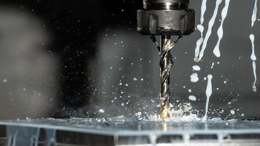
Drilling looks simple from outside the machine. The tool rotates, feeds into the workpiece, and leaves a hole. In real production, that small operation can decide whether a part runs smoothly or turns into a string of oversize holes, broken tools, damaged fixtures, and missed delivery dates.
Most drilling problems are not caused by one dramatic mistake. They usually come from a chain of small details: drill material, point geometry, flute finish, runout, coolant direction, chip evacuation, workholding, and how aggressively the tool is fed at entry and breakthrough. A purchasing team may see only a drill diameter and coating code, while the machinist sees the consequences in chips, noise, burrs, and tool life.
This guide summarizes practical drill bit knowledge for CNC shops and tooling buyers. It covers how solid carbide drills are typically made, how HSS and carbide differ, what features matter on the tool, and how to diagnose common failures such as point wear, margin chipping, built-up edge, and breakage.
Why Drill Quality Matters More Than the Tool Price
A drill is often one of the lowest-cost tools in the setup, but a bad drilling process can create expensive damage. A broken drill may scrap a part that already has milling, turning, heat treatment, or inspection cost in it. Poor hole straightness can force secondary reaming or boring. Unstable chip evacuation can slow a cycle that should have been routine.
For B2B buyers, the useful question is not simply “which drill is cheapest?” A better question is “which drill gives the lowest cost per acceptable hole in this machine, material, and production batch?” That calculation includes tool price, tool life, cycle time, scrap risk, downtime, regrinding potential, and whether the process can be repeated by different operators.
For engineers and production managers, drill selection should begin with the hole requirement. Diameter tolerance, depth-to-diameter ratio, surface finish, through or blind hole design, burr limits, and material condition all influence the tool choice. A general-purpose HSS drill may be enough for repair work or low-volume drilling. A coated solid carbide drill may be the practical choice for high-volume CNC production in alloy steel, cast iron, stainless steel, or abrasive materials.
How Solid Carbide Drills Are Typically Manufactured
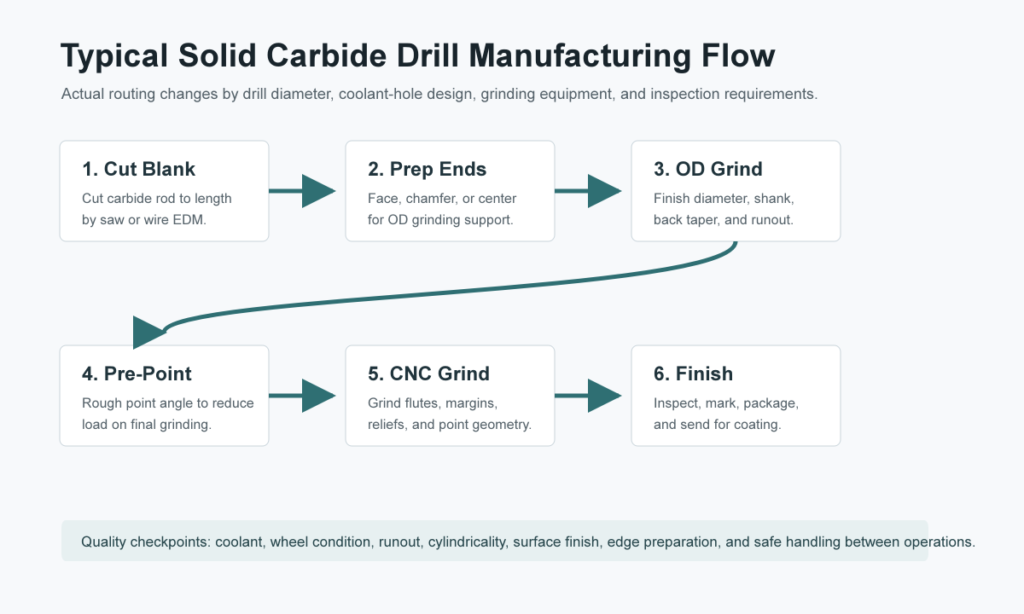
The exact process changes from supplier to supplier, especially for coolant-through drills, micro drills, and special step drills. Still, most solid carbide drill production follows a recognizable route.
First, carbide rod is cut to the required length. Depending on diameter and batch size, the shop may use a carbide rod cutting machine, wire EDM, or another controlled cutting method. The blank must be long enough for the cutting section, flute length, shank, possible neck relief, and grinding allowance.
Next, both ends of the blank are faced. The ends may also be chamfered, center-drilled, or prepared for the specific OD grinding fixture. This sounds like a small step, but it affects how well the blank is supported during cylindrical grinding. Poor support can show up later as runout, taper, or inconsistent shank size.
The blank then goes to OD grinding. On a high-precision cylindrical grinder, the manufacturer grinds the drill outside diameter, shank diameter, back taper or clearance sections, and any necked area. At this stage, cylindricality, surface finish, and radial runout must be controlled. If the OD is not stable, the final drill geometry cannot fully correct the problem.
Many shops rough-grind a pre-point before the blank goes to the five-axis CNC tool grinder. For example, a drill that will finish around a 140 deg point may be pre-ground slightly heavier. This reduces stock removal in the final point grinding operation and improves grinding efficiency.
The most geometry-intensive work happens on the CNC tool grinder. Flutes, margins, web thinning, primary and secondary reliefs, point geometry, chisel edge, and negative edge preparation can be ground here. If the drill has internal coolant holes, the grinding program must align the flutes and point with the coolant outlets. On some modern processes, the machine uses probing or vision systems to locate these features before grinding.
After grinding, some drills receive polishing, especially in the flutes. A smoother flute surface can improve chip evacuation and reduce built-up material in sticky workpiece materials. The finished tool is then inspected, laser marked with brand and size information, packed carefully to protect the cutting edges, and sent for coating when coating is required.
Manufacturing Details That Affect Performance
Several manufacturing details are invisible to buyers but obvious in tool performance. The first is heat control during grinding. Carbide can tolerate high cutting temperatures in use, but abusive grinding can still create thermal damage or microcracks. A good process separates rough and finish grinding, manages coolant, and avoids forcing too much stock removal into one pass.
Wheel condition matters as well. A loaded or glazed diamond wheel can rub instead of cut. That raises heat, reduces surface quality, and can leave a weaker edge. Dressing or opening the wheel at the right time is part of process control, not a cosmetic step.
Handling is another practical point. Finished drill edges are easy to chip before they ever reach the customer’s machine. Well-designed trays, separated pockets, and careful movement between grinding, marking, inspection, coating, and packing reduce edge damage. A drill with a chipped margin may look acceptable at a glance but fail early in the cut.
HSS vs Carbide Drill Materials
High-speed steel and cemented carbide are both common drill materials, but they are built for different strengths.
HSS is a tough tool steel designed to retain hardness at elevated temperature better than ordinary carbon tool steel. It is more forgiving under interrupted cutting, manual feeding, older equipment, and less rigid setups. It can also be easier to resharpen in many workshops. For maintenance, low-volume work, hand drilling, and less demanding materials, HSS remains useful because it balances toughness, cost, and ease of use.
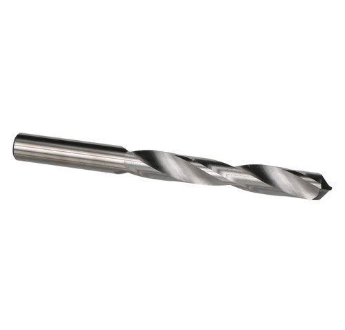
Carbide drills are usually based on tungsten carbide particles bonded with cobalt or another metallic binder. The material is much harder and more wear-resistant than HSS, and it keeps its cutting ability at higher temperature. In a rigid CNC setup, carbide can run much faster and hold hole quality more consistently. The tradeoff is brittleness. Carbide does not like heavy impact, poor alignment, excessive runout, or unstable workholding.
Material | Practical strengths | Practical limits | Best-fit use |
HSS drill | Tough, lower cost, easier to resharpen, forgiving in manual or older machines | Lower heat resistance and cutting speed than carbide | Maintenance drilling, small batches, general shop work, mild materials |
Cobalt HSS drill | Better hot hardness than standard HSS, still relatively tough | Not as rigid or wear-resistant as carbide | Stainless steel and tougher alloys in less rigid setups |
Solid carbide drill | High rigidity, high wear resistance, strong accuracy in stable CNC machines | Brittle under impact, sensitive to runout and poor holding | Production CNC drilling, precision holes, abrasive materials, higher speeds |
Coolant-through carbide drill | Direct cooling and chip flushing at the cutting edge | Needs suitable coolant pressure, filtration, and toolholder support | Deeper holes, stainless steels, alloy steels, high-volume production |
For buyers, the best choice is often not the most advanced material on the list. Carbide is a strong answer only when the machine, holder, coolant, and workholding can support it. HSS can be the better business choice when the setup is flexible, the batch is small, or the workpiece condition is unpredictable.
Geometry Features to Check Before Ordering
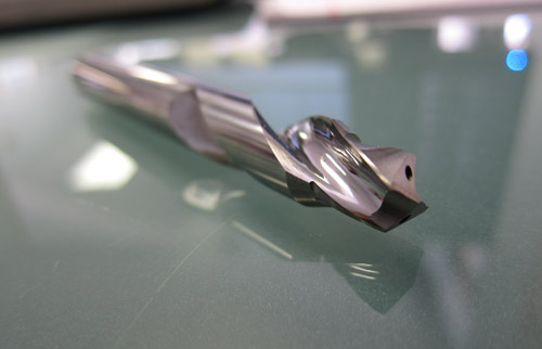
Drill geometry turns tool material into a usable cutting edge. Two drills made from the same carbide grade can behave very differently if their geometry does not match the job.
Point angle affects centering, cutting force, and how the drill enters the material. A 118 deg point is common on many general-purpose drills. A 135 deg or 140 deg point is often used in CNC metal drilling, especially when stronger edge support and smoother entry are needed. The right choice depends on material, hole depth, machine rigidity, and whether a pilot or spot operation is used.
The web and chisel edge influence thrust force. A thick web gives strength but increases axial load if the point is not thinned properly. Web thinning can reduce thrust and improve starting behavior, but excessive thinning can weaken the point.
Margins guide the drill in the hole. They help control diameter and straightness, but they also rub against the hole wall. If the margin is too aggressive, coolant is poor, or chips are re-cut, margins can wear or chip. Back taper reduces rubbing behind the margin and helps the drill avoid binding.
Flute design controls chip formation and evacuation. A polished flute can reduce friction and built-up material. Wider or parabolic flutes may help in deeper holes and ductile materials, while stronger core geometry may be preferred when rigidity and break resistance are more important.
Edge preparation is another hidden detail. A cutting edge that is too sharp may chip quickly in steel or interrupted exits. A negative land or small hone can strengthen the edge. If the preparation is too heavy, however, the drill may need more thrust and generate more heat.
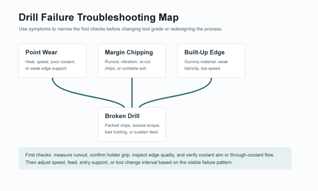
Common Drill Problems and Practical Fixes
When a drill fails, avoid changing several variables at once. Start with the symptom, inspect the tool under magnification if possible, and check the setup before blaming the tool grade.
Problem | Likely causes | Practical corrective actions |
Fast point wear | Cutting speed too high, poor coolant access, weak edge prep, excessive rubbing at entry | Reduce speed, improve coolant direction or through-coolant flow, verify point relief, consider stronger edge prep |
Margin chipping | Runout, weak holder grip, machine vibration, unstable breakthrough, chips packed in flutes | Measure runout near the point, use a more rigid holder, reduce overhang, improve chip evacuation, support the workpiece |
Built-up edge | Sticky low-carbon steel, aluminum, or ductile material welding to the cutting edge | Improve lubricity, use suitable coating or polished uncoated geometry for aluminum, raise speed cautiously, reduce contact time |
Broken drill | Chip clogging, excessive torque, wrong peck strategy, sudden workpiece movement, poor clamping | Shorten tool-change interval, improve coolant and chip control, check spindle and holder, reduce feed at risky entry or exit zones |
Oversize or rough hole | Runout, unequal cutting lips, worn margins, unstable fixture, re-cut chips | Check drill concentricity, inspect point symmetry, verify fixture support, improve coolant and chip evacuation |
Point Wear
Point wear often appears when heat is concentrated at the cutting edge. A drill point that looks rounded or polished may indicate excessive speed, poor coolant contact, insufficient relief, or too much rubbing before the tool begins to cut cleanly. In production, the fix may be as simple as reducing surface speed and improving coolant delivery. In deeper holes, external coolant may not be enough, and a coolant-through drill may be needed.
Feed also deserves attention. Many operators reduce feed when they see wear, but too little feed can make the drill rub instead of cut. If the chip is too thin, heat goes into the tool and workpiece instead of leaving with the chip. The better adjustment depends on chip shape, sound, spindle load, and material.
Margin Chipping
Chipping near the margin or land often points to instability. The drill may be running out of center, the holder may not grip evenly, or the workpiece may move under drilling thrust. Runout should be measured close to the drill point. A practical target for high-quality carbide drilling is often below 0.02 mm, and precision work may need tighter control.
If chipping occurs at breakthrough, the workpiece may be springing or the drill may lose support suddenly as it exits. A stronger holder, shorter overhang, pilot hole, more stable fixture, or feed reduction near exit can help. For difficult holes, a drill with stronger back taper, margin design, or edge preparation may be required.
Built-Up Edge
Built-up edge is common in materials that smear or weld to the cutting edge. Low-carbon steel, some stainless steels, and aluminum can produce this behavior when cutting temperature, pressure, and lubrication are poorly balanced. The symptom may be unstable hole size, poor finish, and a cutting edge that looks like it has material stuck to it.
Better lubrication can help, especially when the current coolant concentration is weak or the fluid does not reach the point. In aluminum, a polished uncoated drill can sometimes outperform a coated drill because chips slide more easily and adhesion is reduced. In steel, a suitable coating and correct speed/feed window may be more important.
Broken Drills
Broken drills often come from chip packing. When chips cannot escape, torque rises quickly. The operator may see only a sudden break, but the real cause began earlier with long stringy chips, poor coolant flow, excessive hole depth for the flute design, or a peck cycle that did not actually clear the chips.
Workholding matters too. If the part moves downward under thrust and springs back at breakthrough, the drill can be overloaded. A weak holder can let the drill slip. A worn spindle bearing or damaged slide can add vibration. Before switching to a tougher grade, confirm the mechanical setup.
A Practical Selection Checklist
Selection item | What to confirm | Why it matters |
Workpiece material | ISO group, hardness, condition, coating or scale, heat treatment | Material controls cutting speed, edge prep, coating, and coolant needs |
Hole specification | Diameter, depth, tolerance, finish, straightness, through or blind hole | The hole requirement decides whether HSS, carbide, reaming, or boring is needed |
Machine condition | Spindle runout, power, rigidity, coolant pressure, tool changer repeatability | Carbide delivers value only when the system can support it |
Toolholding | Collet quality, hydraulic or shrink-fit holder, overhang, clamping length | Poor holding causes runout, slipping, chipping, and breakage |
Chip evacuation | Flute type, coolant method, peck strategy, chip shape | Chip packing is one of the fastest ways to break a drill |
Tool finish | Flute polish, coating, edge prep, margin condition | These details influence heat, adhesion, and hole wall quality |
Batch economics | Tool price, regrind option, tool life, cycle time, scrap risk | The best drill is the one that lowers cost per acceptable hole |
Notes for Tooling Buyers
When sending an RFQ for drills, include more than diameter and length. A supplier can recommend a better tool if the request includes workpiece material and hardness, hole depth, through or blind hole design, tolerance, coolant pressure, machine type, holder type, and current problem symptoms.
If the shop already has a failing drill, share the failure mode. “Broken after 80 holes in 304 stainless, 8xD blind hole, external coolant only” is much more useful than “need stronger drill.” Photos of the worn edge, chips, and setup can shorten the diagnosis.
For repeat production, ask about regrinding and recoating. Some solid carbide drills can be reground several times if there is enough geometry allowance and edge damage is not severe. Regrinding is not free, but it can reduce tooling cost when the process is stable and the supplier can restore the original geometry accurately.

Conclusion
Good drilling is built from matched details. The drill material must fit the machine and workpiece. The geometry must support the hole requirement. The grinding process must protect the edge. The holder, coolant, feed, and chip evacuation must let the tool do its job.
For HNCarbide customers, the most useful starting point is a clear application description: material, hardness, hole size, depth, machine, coolant, and the problem you want to solve. With that information, a drill can be selected or customized around the real cost per hole, not just the price printed on the tool box.




