
Five Common CNC Lathe Toolholder Clamping Methods: D, P, M, W and S Types
Table of Contents
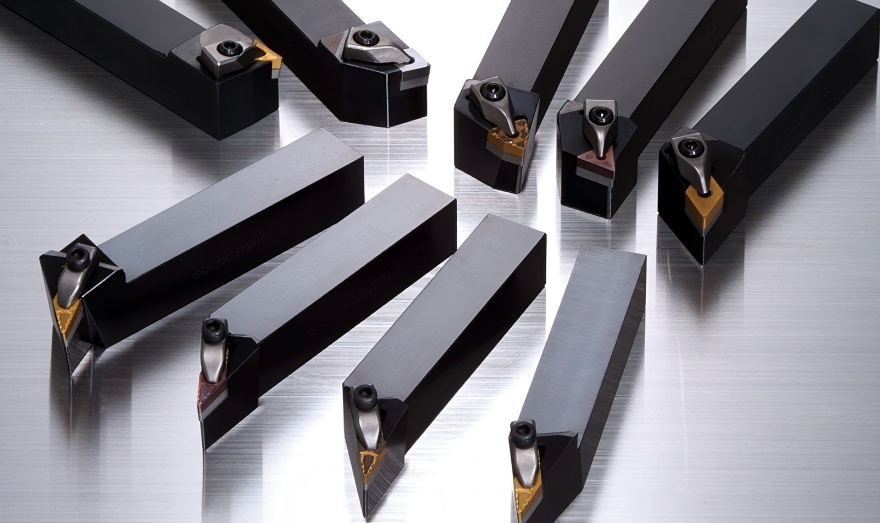
In CNC turning, the insert grade and chipbreaker usually get most of the attention. The clamping structure behind the insert can matter just as much. It affects how firmly the insert sits in the pocket, how well the edge resists vibration, how freely chips leave the cutting zone, and how quickly an operator can index a worn corner.
This is especially important for B2B buyers and production shops because two toolholders that accept similar inserts can behave very differently under load. A holder that works well for light finishing may lose stability in interrupted cuts. A heavy-duty holder may hold the insert beautifully, but slow down indexing or leave less room for chip evacuation.
This guide compares five common clamping methods used on CNC lathe turning toolholders: D type, P type, M type, W type and S type. The aim is not to rank one design as best for every job. The better question is: which clamping structure fits your insert style, cutting load, chip control requirement and maintenance habits?
Quick comparison of the five clamping types
Clamping type | Common structure | Typical insert style | Best fit | Main caution |
D type | Top clamp or clamp plate | Negative-rake inserts | Rigid general turning, batch production, stable external turning | Clamp can occupy some chip-flow space above the insert. |
P type | Internal lever clamping | Negative-rake inserts | Heavy-duty turning where chip evacuation matters | Lever mechanism must be kept clean and in good condition. |
M type | Eccentric screw plus auxiliary clamp | Negative-rake inserts | Cost-sensitive general-purpose turning | Lower ultimate clamping force than heavier systems. |
W type | Wedge clamping with center location | Heavy-duty negative-rake applications | High-rigidity roughing, high load, stable machines | More complex indexing and higher cleanliness requirement. |
S type | Direct screw clamping through the insert hole | Positive-rake inserts and some dedicated negative inserts | Light turning, boring, small-space machining, good chip clearance | Lower load capacity than strong clamp or wedge systems. |
Why the clamping method changes cutting performance
The insert needs two things at the same time: accurate location and reliable support under cutting force. If the pocket, screw, lever or clamp lets the insert move even slightly, the operator may see chatter, poor finish, corner chipping, damaged seats or inconsistent tool life.
The clamping method also affects chip flow. Any part placed above the rake face, such as a top clamp, can reduce the open space available for chips. That may not matter in many external turning jobs, but it can become noticeable when machining stainless steel, ductile materials, deep shoulders or internal features where chips already have a narrow exit path.
Maintenance is part of the decision as well. A simple screw clamp is easy to understand and service. A lever or wedge system can deliver excellent holding strength, but chips, fine dust and coolant residue must not interfere with the moving parts. In a clean, disciplined production cell, this is rarely a problem. In rough shop-floor conditions, it deserves attention.
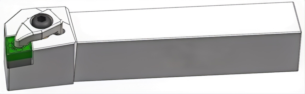
D type clamping: top clamp for strong, simple holding
D type clamping uses a top clamp plate to press down on the insert from above. It is commonly used with negative-rake turning inserts and remains one of the classic clamping structures in CNC turning. The insert is held against the pocket location faces while the clamp applies force across the top surface.
The main advantage is rigidity. Because the clamp contacts a relatively broad area, the insert can be held firmly under medium and heavy cutting loads. The clamping force helps push the insert into the toolholder seat, reducing the chance of micro-movement during continuous turning.
D type holders are also practical for production. The structure is easy to understand, the parts are not overly delicate, and indexing is usually straightforward. For shops running repeated batches of steel, cast iron or general alloy parts, this balance of strength and convenience is a major reason D type holders remain common.
The tradeoff is chip clearance above the insert. The top clamp does not usually block chips completely, but it does occupy part of the space near the rake face. In applications where chips curl upward aggressively or need a very open path, this can be less ideal than lever or screw clamping with an unobstructed cutting area.
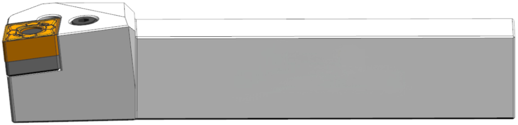
P type clamping: lever locking for heavy-duty turning and open chip flow
P type clamping uses an internal lever mechanism. Instead of pressing on the insert from the top, the mechanism pulls the insert into its locating surfaces from the side or through the insert hole, depending on the holder design. It is generally paired with negative-rake inserts and is often selected for heavier turning work.
The open rake face is the first practical benefit. With no external top clamp sitting over the insert, chips can leave the cutting zone more freely. This helps when machining materials that form long or springy chips, and it is useful when the part geometry leaves little extra space around the cutting edge.
P type clamping also gives strong seating when the lever and pocket are in good condition. The insert is drawn tightly against the holder’s location faces, which supports stable cutting under heavier loads and interrupted cuts. Operators often like this design because indexing can be smooth while the insert still seats repeatably.
The main caution is maintenance. The lever system has internal parts and contact surfaces that must stay clean. Fine chips, dust, dried coolant or damage inside the mechanism can reduce clamping reliability. For high-volume shops, a simple inspection routine usually prevents problems: clean the pocket, check lever movement and replace worn screws or pins before they fail during production.
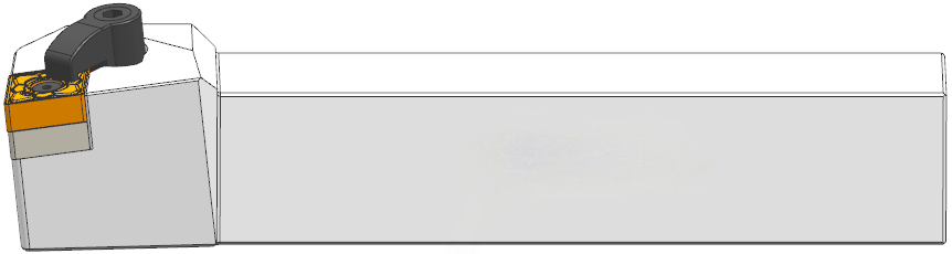
M type clamping: economical compound clamping for general use
M type clamping is widely used because it gives a practical compromise between cost, availability and day-to-day usability. The design commonly combines eccentric screw positioning with an auxiliary clamp. The eccentric screw helps push or locate the insert against the pocket, while the clamp adds holding force.
For buyers, the appeal is clear: the structure is simple, replacement parts are easy to understand, and the holder price is usually competitive. M type holders are common in distribution channels and fit many standard negative-rake turning inserts. For light and medium turning, they often provide enough stability without the cost of a more complex heavy-duty clamping system.
The limitation appears when cutting loads rise. Compared with stronger lever, top-clamp or wedge systems, M type clamping has less reserve holding force. It may not be the best choice for severe interrupted cuts, high-depth roughing or applications where the insert is exposed to repeated impact.
Indexing can also take a little more time because the operator may need to loosen and reposition more than one contact element. That is not a serious issue for small batches, repair work or general turning, but it matters in production cells where every tool change is counted.
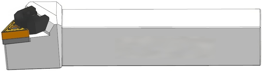
W type clamping: wedge force for maximum rigidity
W type clamping is a high-rigidity wedge structure. A center pin or locating feature positions the insert, while wedge blocks are tightened from the side. As the wedge moves, its angled surface converts screw tightening into lateral pressure against the insert. The result is a strong, controlled clamping force.
This design suits demanding turning applications where insert movement cannot be tolerated. Heavy roughing, higher cutting force, interrupted stock and rigid machine setups are typical reasons to consider wedge clamping. When the wedge faces, insert pocket and center location are clean, the insert can sit with very little play.
The structure also resists deformation well. Because the force is distributed through the wedge and pocket, the holder can maintain accurate positioning over long production runs. That matters when a shop is trying to protect both the insert edge and the toolholder seat during heavy cuts.
The price for this stability is complexity. Wedge components require careful installation, cleaning and inspection. Chips or dirt under a wedge can affect positioning. Indexing is usually slower than simpler systems, and manufacturing cost is higher. W type clamping is therefore easiest to justify when the job genuinely needs the extra rigidity.
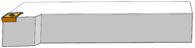
S type clamping: direct screw locking for open access and lighter loads
S type clamping uses a screw through the insert mounting hole to lock the insert directly to the toolholder. The structure is simple, compact and free from external clamps. It is widely used with positive-rake inserts and can also appear in some dedicated negative-rake designs.
Its biggest benefit is access. Because there is no clamp above the insert, the cutting zone stays open. This is valuable in small-diameter boring, internal profiling, light finishing and other jobs where space is limited. Chip flow is usually clean, and the operator has a clear view of the insert corner.
S type clamping also keeps the toolholder design compact. For boring bars and small holders, that can be more important than maximum clamping force. The insert can be indexed quickly, and there are fewer separate clamping parts to manage.
The weakness is load capacity. A center screw applies concentrated holding force, but it does not provide the same broad support as a clamp plate or wedge system. In heavy roughing, severe interruption or unstable external turning, an S type holder may not give enough resistance to insert movement. It works best when the cutting load is moderate, the insert geometry is sharp, and the setup does not demand brute-force clamping.
Application guide by machining condition
Machining condition | Better clamping choices | Why it fits |
General external turning on steel | D type or M type | D gives stronger support; M keeps cost low for routine work. |
Heavy roughing or interrupted cuts | P type, W type or strong D type | These structures provide better resistance to insert movement under impact. |
Stainless steel with difficult chip flow | P type or S type when the load is light enough | Open rake-face access helps chips evacuate instead of packing around a clamp. |
Small boring or internal finishing | S type | Compact structure and open cutting zone suit limited space. |
High-volume production with frequent indexing | D type or P type | Both can combine repeatable location with efficient insert changes. |
Cost-sensitive mixed workshop use | M type | Good general-purpose coverage when cutting loads are not extreme. |
High-rigidity roughing on stable machines | W type | Wedge locking provides strong seating for demanding cuts. |
Common clamping-related problems and corrections
Problem seen in production | Possible clamping-related cause | First correction to try |
Insert corner chips early | Insert is not fully seated, clamping force is low, or holder is too light for the cut | Clean the pocket, inspect screws and seats, then consider a stronger clamping type. |
Chatter appears after indexing | Chip or burr under the insert, uneven clamp pressure, worn screw | Remove the insert, clean the pocket and check contact marks before changing cutting data. |
Long chips pack around the insert | Top clamp reduces chip-flow space or chipbreaker is outside its working range | Improve chipbreaker/feed first; if space is the issue, consider P or S type clamping. |
Insert position varies after each change | Damaged locating surface, worn lever/wedge/screw, mixed insert-holder compatibility | Inspect the location faces and replace worn clamping parts. |
Screw or clamp wears quickly | Overtightening, poor lubrication of screw threads, impact load beyond holder design | Use correct tightening practice and match holder type to cutting load. |
Buyer checklist before choosing a toolholder clamping type
When purchasing CNC lathe toolholders, avoid selecting only by shank size and insert code. The clamping method should match the job.
Check item | What to confirm |
Insert geometry | Positive or negative insert, center hole style, insert thickness and compatible pocket design. |
Cutting load | Finishing, medium turning, roughing, interrupted cut or heavy-duty production. |
Chip evacuation | Whether chips need an open rake face or whether a top clamp will be acceptable. |
Indexing frequency | How often operators change edges and how much downtime the process can tolerate. |
Maintenance discipline | Whether the shop can keep lever and wedge mechanisms clean and inspected. |
Holder cost vs. downtime | Whether a lower-cost holder is still economical if it causes tool movement or slow indexing. |
Machine rigidity | Whether the lathe, turret, workholding and overhang can make use of a heavy-duty holder. |

Conclusion
D, P, M, W and S type clamping systems all have a place in CNC turning. D type clamping offers strong, simple support for negative inserts. P type lever clamping keeps the rake face open while giving heavy-duty seating. M type clamping is economical and versatile for general work. W type wedge clamping is the high-rigidity choice when the cut is demanding. S type screw clamping is compact and clean, especially for positive inserts, internal turning and lighter loads.
For most shops, the best toolholder lineup includes more than one clamping style. Use the economical general-purpose holder where the job allows it, and move to a stronger or more open clamping structure when cutting load, chip flow or repeatability demands it.
HNCarbide supports carbide turning insert and toolholder selection for production turning, boring, profiling and general CNC machining. If you are comparing clamping methods for a specific material or operation, start with the real cutting condition first. The holder should serve the process, not just match the insert code.




