
Climb Milling vs. Conventional Milling: How to Choose the Right Cutting Direction
Table of Contents
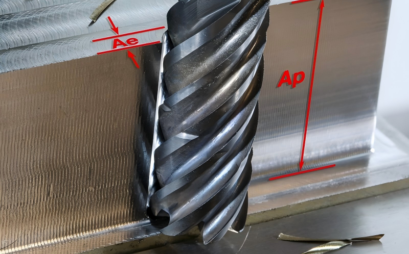
Milling direction looks simple until a job starts leaving chatter marks, pulling a thin wall out of shape, or chipping a cutter on the first pass across a casting skin. In many shops, the discussion gets reduced to a quick rule: use climb milling on CNC machines and conventional milling on older manual machines. That rule is useful, but it is not enough.
The real decision depends on the relationship between cutter rotation and feed direction. Change the toolpath and the same rotating cutter can move from climb milling to conventional milling. Change the machine condition, stock surface, or finishing requirement, and the preferred direction may change again.
This guide explains the difference in plain shop-floor terms, then turns it into a practical selection method for CNC programmers, machinists, production managers, and tooling buyers.
What Is Climb Milling?
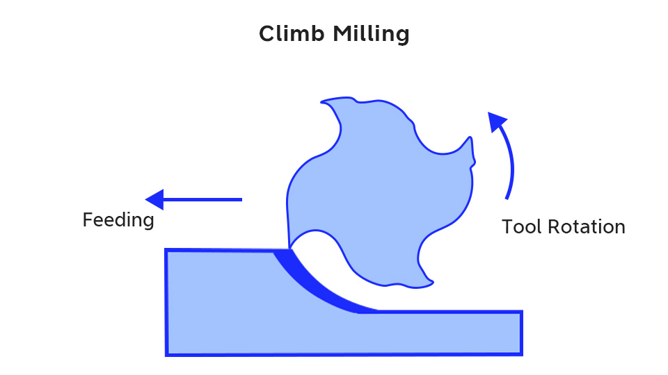
Climb milling, also called down milling, happens when the cutter rotation at the cutting point moves in the same direction as the feed. The chip starts thick and becomes thinner as the tooth exits the cut.
That thick-to-thin chip formation is the key. The cutting edge bites immediately instead of rubbing before it cuts. Less rubbing usually means less heat at the edge, lower tendency toward work hardening, better surface finish, and longer tool life when the setup is rigid enough.
Climb milling also tends to push the workpiece downward into the table during many peripheral milling cuts. That can help with thin-wall parts or lightly supported work, provided the part is clamped well and the machine does not have enough backlash for the cutter to pull the table forward.
On modern CNC machining centers with ball screws, good servo control, and stable fixturing, climb milling is often the first choice for finishing and many semi-finishing operations. It is especially useful when surface finish and dimensional consistency matter more than simply roughing away stock as fast as possible.
What Is Conventional Milling?
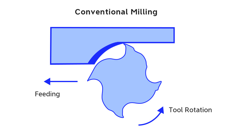
Conventional milling, also called up milling, happens when the cutter rotation at the cutting point moves against the feed direction. The chip starts nearly at zero thickness and grows thicker as the tooth moves through the material.
This thin-to-thick chip formation changes the behavior of the cut. At entry, the edge may rub before it gets enough chip load to cut cleanly. That rubbing can increase heat, accelerate edge wear, and create a poorer finish. In work-hardening materials, rubbing at the start of the cut can also harden the surface before the edge fully engages.
So why use conventional milling at all? Because it is more forgiving in several real-world situations. It is safer on machines with noticeable backlash because the cutter is less likely to pull the table into the cut. It can also be useful when cutting through hard scale, oxide layers, forged skin, or casting skin, because the edge enters more gradually instead of striking the hardest layer at maximum chip thickness.
The Chip Thickness Difference
The difference between climb and conventional milling is not a naming detail. It changes how the cutting edge enters material, how heat forms, how the force acts on the workpiece, and how the tool wears.
Factor | Climb milling | Conventional milling |
Feed and cutter motion | Same direction at the cutting point | Opposite direction at the cutting point |
Chip thickness | Starts thick, exits thin | Starts thin, exits thick |
Edge behavior at entry | Cuts immediately with less rubbing | May rub before cutting fully |
Surface finish tendency | Usually better on rigid CNC setups | Often rougher due to rubbing and chip flow |
Tool life tendency | Often longer in stable conditions | Often shorter in finishing, but safer in some rough stock |
Machine requirement | Low backlash and good rigidity | More tolerant of backlash |
Typical use | CNC finishing, side milling, stable roughing | Manual milling, hard skin removal, unstable setups |
For carbide end mills and indexable milling cutters, this difference can decide whether the edge wears gradually or fails suddenly. Carbide handles compressive load well, but it does not like uncontrolled impact, chatter, or edge chipping. The milling direction must work with the tool grade, coating, edge prep, and holder rigidity rather than against them.
Why Climb Milling Is Often Preferred on CNC Machines
Modern CNC milling favors climb milling because the machine can control feed motion accurately and resist backlash. When the table and servo system hold position well, the advantages of climb milling become easier to capture.
First, the tool does less rubbing. The tooth enters with a real chip load, so the edge spends less time sliding across the surface. That helps reduce heat and wear at the cutting edge.
Second, finish is usually better. In side milling and profile finishing, climb milling tends to leave a cleaner wall because the cutting action is more decisive and the chip is carried behind the cut instead of being pushed ahead of the edge.
Third, the cutting force often helps press the workpiece down. This can be useful in thin-wall machining, light finishing, and parts where vibration shows up as wall marks. It does not replace good fixturing, but it can make a stable setup behave more quietly.
Fourth, climb milling often supports smoother chip evacuation. Chips tend to move away from the finished surface, which reduces the chance of recutting chips and scratching the wall. This is especially useful on side walls, shoulders, and finishing passes where a small chip mark can become a visible quality issue.
Where Climb Milling Can Cause Trouble
Climb milling is not a magic default. If the machine has backlash, the cutter can pull the table or workpiece forward. That sudden motion can cause overcutting, chatter, tool breakage, or a damaged part. This is why conventional milling remains common on older manual mills and on machines with worn screws or loose feed mechanisms.
Climb milling also hits the surface at maximum chip thickness. If the stock has a hard oxide layer, casting skin, forged scale, or sand-contaminated surface, that first impact can chip the edge. In those cases, conventional milling or a sacrificial roughing pass may protect the tool better.
Another risk is poor workholding. Because climb milling can pull the work into the cutter, weak clamping or thin unsupported stock may move. On a rigid CNC machine this is usually manageable, but only if the fixture, tool stickout, and engagement are under control.
The practical point is simple: climb milling rewards stability. It punishes looseness.
When Conventional Milling Is the Better Choice
Conventional milling is still useful when the setup needs a more cautious entry into the cut.
It is often a safer starting point in these situations:
– Manual milling machines or older machines with measurable backlash.
– Roughing castings, forgings, flame-cut stock, or parts with hard scale.
– Setups with limited rigidity where sudden cutter pull-in would be risky.
– Early roughing passes where surface finish is less important than protecting the tool and machine.
– Specific side milling cases in hardened or abrasive material where testing shows better edge security.
Conventional milling can also be used deliberately before switching to climb milling. For example, a shop may remove the hard outer skin of a casting with conventional milling, then finish the clean base material with climb milling. That combination often makes more sense than forcing one strategy through the entire job.
Toolpath Direction Matters More Than Many People Think
A common misunderstanding is that the spindle rotation alone decides whether the cut is climb or conventional. It does not. The decision comes from the relative direction between cutter rotation and feed at the contact point.
This is why CAM toolpath strategy matters. A bidirectional zig-zag roughing path may alternate between climb milling and conventional milling on every pass. That can be efficient for material removal, but it also changes cutting force direction, tool load, chip flow, and finish from pass to pass.
A one-way finishing path, by contrast, can keep the cutter in climb milling for the whole wall. It may take slightly more non-cutting motion, but the cut is more consistent. For precision walls, thin features, and visible surfaces, that consistency is often worth the extra travel.
Contour direction matters as well. With a typical right-hand cutter and clockwise spindle rotation, outside profiles and inside pockets do not behave the same way. Many CNC programmers use climb milling for an outside profile by feeding clockwise around the part, while climb milling inside a pocket generally requires the opposite contour direction. CAM software can manage this, but the programmer still needs to verify the strategy instead of trusting a label.
Choosing by Application
Application or condition | Better starting choice | Why |
CNC finishing on clean steel or aluminum stock | Climb milling | Better wall finish, less rubbing, more consistent edge engagement |
Thin-wall side milling on a rigid CNC setup | Climb milling | Cutting force can help press the part down and reduce rubbing |
Manual knee mill with backlash | Conventional milling | Reduces risk of cutter pull-in and overcutting |
Cast or forged surface with hard skin | Conventional milling first | Edge enters gradually instead of striking the hard layer at full chip thickness |
Bidirectional roughing where cycle time matters | Mixed, with monitoring | Efficient, but expect alternating force and finish behavior |
Final profile pass on a critical wall | One-way climb milling | Consistent direction improves surface and size control |
Roughing unstable stock or weak workholding | Conventional or reduced-engagement climb test | Safety depends on fixture, backlash, and cutter pull-in risk |
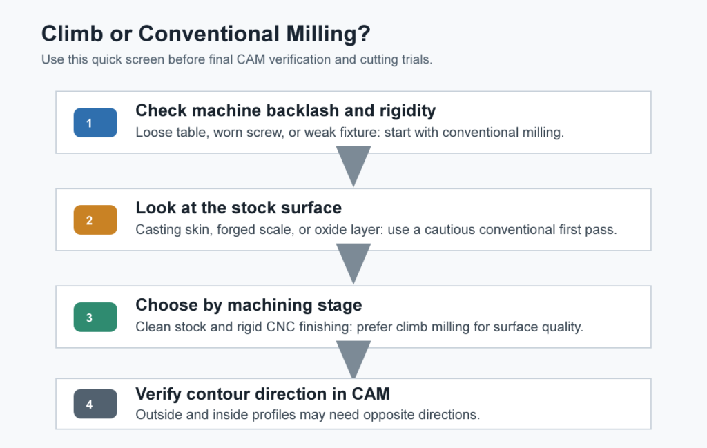
Before finalizing the CAM program, use a simple screening sequence: check backlash and rigidity first, check whether the stock has a hard surface layer second, then decide whether the operation is roughing, semi-finishing, or finishing. If the machine is rigid and the material surface is clean, climb milling is usually the better finishing direction. If the setup is loose or the first pass must break through scale, conventional milling is often the safer starting point.
Tooling Considerations for Carbide Cutters
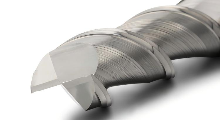
Carbide tools benefit from stable chip formation. A solid carbide end mill with the right flute geometry can perform very well in climb milling because the edge cuts cleanly and chips leave the zone more easily. In aluminum, polished flutes and suitable rake help prevent chip welding. In steels, coatings such as AlTiN, TiAlN, or AlCrN are often selected for heat and wear resistance, but coating alone cannot compensate for chatter or poor engagement.
For roughing, variable pitch end mills and chipbreaker geometries can help control vibration and chip size. For finishing, a sharp, stable edge and low runout are more important than aggressive stock removal. In either case, milling direction should match the tool’s intended use.
If a cutter chips early in climb milling, do not assume climb milling is wrong. Check radial engagement, tool stickout, holder runout, material skin, spindle load, and fixturing. If the setup is rigid and the material is clean, reducing engagement or changing the cutter geometry may solve the issue. If the machine has backlash or the stock surface is abrasive, conventional milling may be the correct first pass.
Troubleshooting Direction-Related Problems
Problem seen in the cut | Likely direction-related cause | Practical response |
Cutter grabs or table jumps | Climb milling on a machine with backlash | Use conventional milling, repair backlash, or move to a controlled CNC setup |
Chipped edge on first pass over casting | Climb milling hits hard skin at maximum chip thickness | Use conventional roughing pass or remove skin with a dedicated operation |
Poor wall finish in finishing pass | Conventional milling rubbing or chip recutting | Try one-way climb finishing with correct stock allowance |
Chatter marks on thin wall | Alternating force from bidirectional path or weak support | Use one-way climb pass, reduce radial engagement, improve support |
Work hardening in stainless | Rubbing at low chip thickness, often in conventional entry | Maintain proper chip load and consider climb milling on a rigid setup |
Burrs on exit edge | Toolpath direction and chip flow pushing material | Adjust climb/conventional side, cutter sharpness, and finishing allowance |
A Practical Selection Method
Start with the machine. If it has meaningful backlash or a loose feed system, conventional milling is usually the safer default. If it is a modern CNC machine in good condition, climb milling becomes the normal first choice for clean material and finishing.
Next, look at the stock surface. Clean bar stock, pre-machined blanks, and stable aluminum plates usually favor climb milling. Castings, forgings, flame-cut edges, oxidized surfaces, and scaled material deserve more caution. A conventional roughing pass can protect the cutter before climb finishing.
Then decide by machining stage. Roughing may prioritize tool security, chip evacuation, and cycle time. Semi-finishing begins to care about force direction and wall stability. Finishing should usually use a consistent direction, often climb milling, so the last pass leaves a predictable surface.
Finally, verify the toolpath. Do not rely only on a CAM operation name. Check whether the actual contact point is climb or conventional, especially on pockets, islands, outside contours, and zig-zag strategies.

Conclusion
Climb milling and conventional milling are not simply “modern” versus “old-fashioned” methods. They are different ways of forming a chip, loading the cutter, and controlling the workpiece. Climb milling usually gives better tool life and surface quality on rigid CNC machines with clean material. Conventional milling remains useful for backlash-prone machines, rough stock with hard skin, and cautious first passes.
The best shops treat milling direction as part of the whole process: machine condition, material surface, workholding, cutter geometry, coating, engagement, and toolpath strategy. For B2B tooling buyers, this is also a reminder that a carbide end mill should not be selected by diameter and coating alone. HNCarbide can help match cutter geometry and carbide grade to the way the part will actually be milled.




