
Cross-Hole Drilling Problems: Feed, Coolant, Tool Support, and Burr Control
Table of Contents
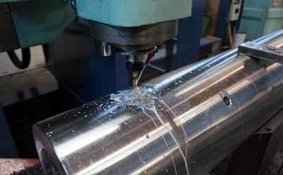
Cross holes look simple on a print. One hole breaks into another. The part may be a mold insert with water-cooling channels, a crankshaft with oil passages, a hydraulic block, a valve body, or a fixture component with intersecting ports. On the machine, the job is less tidy.
A drill cuts best when the cutting lips stay supported and the load stays balanced. In cross-hole drilling, that support disappears for part of the rotation. The drill enters a curved opening, loses contact on one side, starts cutting again on the opposite wall, and often exits into another void. That is why a job that ran well in a straight blind hole can suddenly produce chipped edges, rough walls, burrs, oversize holes, broken drills, or a sound that makes the operator reach for the feed hold.
The answer is not always to give up on the part or move the job to a different process. Most cross-hole problems come from a small group of causes: interrupted cutting, poor chip evacuation, too much tool overhang, unstable entry geometry, and a tool design that was never meant for that kind of break-through. This guide focuses on the practical controls a shop can adjust before scrap and tool breakage become routine.
Why cross holes are hard on drills
In ordinary drilling, both cutting lips share the work. The chisel edge starts the hole, the margins help guide the tool, and the flutes carry chips away. Even then, deep holes need careful control because chips form inside the workpiece instead of in open space.
Cross holes disturb that balance. When the drill reaches the intersecting bore, one lip may lose contact before the other. The tool sees a sudden change in thrust and radial force. If the drill is long, slender, or poorly supported, it can deflect. If the cutting edge is already worn, the shock at break-through can chip the edge. If chips fall into the intersecting cavity and get pulled back into the cutting zone, they may scratch the bore or damage the margin.
The exit side can be just as troublesome. The drill does not always break through cleanly into the far wall of the intersecting hole. It may grab, chatter, or leave a burr that later blocks coolant, traps oil sludge, or breaks loose inside the part. In mold cooling channels and engine oil passages, that loose burr is more than a cosmetic defect.
Cross-hole condition | What the drill experiences | Common result |
Drill passes through the center of a round cross bore | Momentary loss of support, then re-entry into the far wall | Moderate vibration, possible exit burr |
Drill enters an off-center intersecting bore | Uneven cutting load and longer unsupported contact | Hole drift, chatter, lip chipping |
Drill enters at 45 degrees or 30 degrees | Longer angled break-through zone | More deflection and higher burr risk |
Deep hole over 10xD before the intersection | More overhang and weaker chip evacuation | Packing, torque rise, poor finish |
Small hole breaks into a larger cavity | Chips can drop, roll, and recut | Scratched bore, edge damage, shorter tool life |
Start with feed control at the intersection
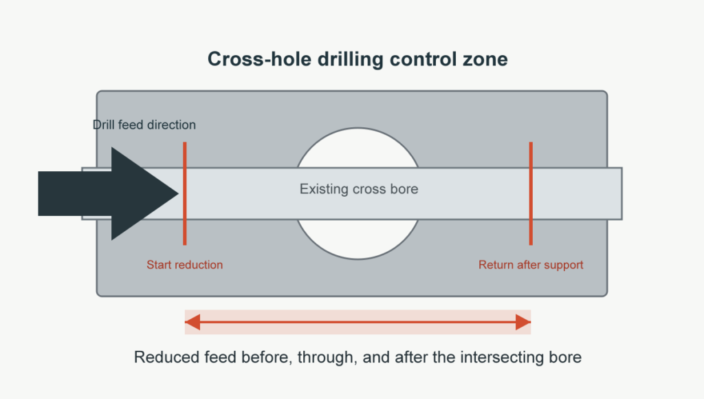
The first adjustment is usually feed. A full feed rate may be fine while the drill is cutting solid material, but it can be too aggressive when the drill reaches the cross hole. Many shops start by reducing feed by 25-75 percent as the drill approaches, enters, and exits the intersecting bore. A 50 percent feed reduction is a reasonable starting point, then the process can be tuned from the sound, chip shape, spindle load, and finished hole quality.
The program does not need to run slowly through the entire hole.
A better pattern is often:
Tool position | Programming approach | Reason |
Stable entry in solid material | Use normal proven feed and speed | Keeps cycle time under control |
1-2 diameters before the cross hole | Reduce feed before the drill loses support | Lowers shock load on the cutting edge |
Passing through the intersecting bore | Maintain reduced feed and avoid sudden acceleration | Reduces chatter and deflection |
Re-entering the far wall | Keep feed reduced until the drill is fully supported again | Helps protect the lips and margins |
After the interrupted zone | Return to normal feed if chips and load are stable | Recovers productivity |
Speed may also need attention, but feed is normally the cleaner first move. Lowering spindle speed can reduce vibration in some cases, especially with gun drills and long drills. A lower withdrawal speed may also help prevent whipping when a long tool backs out of the hole. Still, cutting too slowly can create rubbing, heat, and work hardening in stainless steel, heat-resistant alloys, and other difficult materials. If the drill starts polishing instead of cutting, slowing down has gone too far.
The geometry of the intersection matters. A drill crossing the centerline of a large, round bore sees a more predictable interruption than a drill entering an off-center curved wall. A shallow 30-degree intersection usually needs more caution than a 90-degree intersection because the drill spends more time with partial support. In those cases, a longer reduced-feed zone is usually safer than a sudden feed drop at the exact break-through point.
Keep chips from becoming a second cutting tool
Chip evacuation decides many cross-hole jobs. A chip that leaves cleanly is harmless. A chip that packs in the flute, falls into the intersecting hole, or gets pushed ahead of the cutting edge becomes a second cutting tool. It rubs the bore, marks the surface, and can chip the drill edge.
Through-coolant is strongly preferred for deep or intersecting holes. It delivers coolant to the cutting edge, helps control heat, and pushes chips away from the cutting zone. The coolant system must provide enough pressure and flow for the drill diameter. Pressure without flow may not move the chips. Flow without filtration can send fine particles back through the tool and accelerate wear.
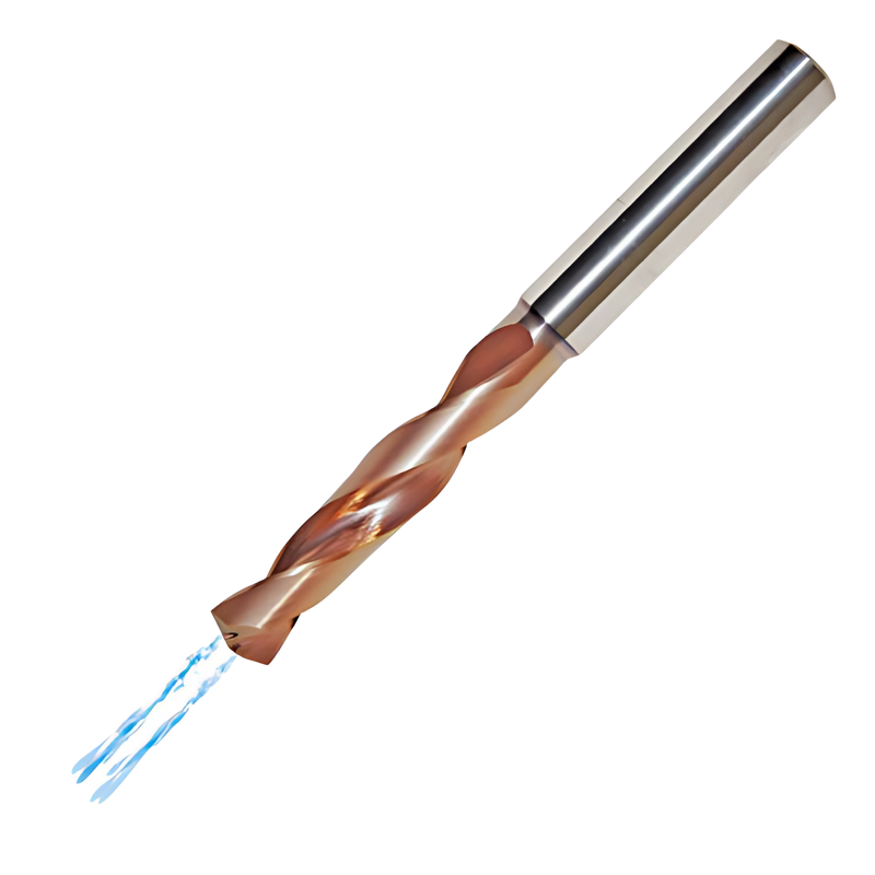
When a smaller hole breaks into a larger hole, chips often have room to drop out of the flute path. That sounds helpful, but it can create a new problem: loose chips collect in the cavity and get dragged back across the edge as the drill re-enters. High-pressure internal coolant, a clean exit path, and a planned flushing cycle can make the difference between a stable process and a hole full of scratches.
For deep holes, operators still learn a lot from chip shape and sound. Short, consistent chips suggest a healthier cut. Long stringy chips, blue chips, powdery chips, or sudden changes in sound deserve attention. Shops with spindle load, torque, coolant pressure, acoustic, or vibration monitoring have an advantage, but the process should not depend only on alarms. The program and coolant delivery should already be built to survive the interruption.
Use the shortest drill that can do the job
Rigidity is cheap insurance. A shorter drill deflects less, vibrates less, and gives the cutting edges a better chance of staying aligned as the tool passes through the interrupted zone. If the hole can be made with a shorter length series, choose it. If the part requires a long reach, reduce every avoidable source of overhang in the holder, fixture, and setup.
This is especially important when drilling toward a large cross bore. The larger the intersecting hole, the wider the unsupported zone. The drill point may contact the far side of the cross bore before the margins regain full guidance. Ideally, the drill center and chisel area contact before the outside lip is forced sideways. If the side of the drill contacts first, the tool can be pushed off path.
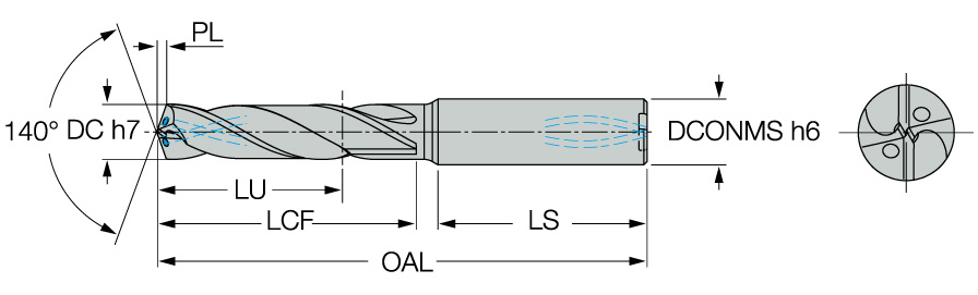
Tool length is not the only stiffness issue. Check holder runout, spindle condition, bushing support if used, turret alignment on lathes, and fixture rigidity. A good carbide drill can still fail if one lip does most of the work. For long holes, even small setup errors become visible at the intersection.
Match the drill type to the interruption
Different drill styles react differently to cross holes. Solid carbide drills give strong accuracy and rigidity, but the cutting edges can chip if shock loading is high. Indexable drills are economical for larger diameters, though they may need careful feed control because insert geometry and body stiffness vary widely. Crown drills and replaceable-tip drills can be attractive in production because worn cutting edges are replaced without changing the whole body.
Gun drills and other deep-hole tools deserve special attention. They rely on guide pads, coolant flow, and stable support along the bore. When they cross an open space, vibration can rise quickly. Slower feed through the intersection, lower withdrawal speed, strong coolant flow, and a controlled pilot or guide strategy can help. In some cases, the toolmaker may add guide-pad support or adjust the head design for the interrupted section.
Drill choice | Where it can work well | Watch-outs in cross holes |
Solid carbide drill | Accurate small and medium holes on stable CNC machines | Edge chipping if feed is too high at break-through |
Through-coolant carbide drill | Deeper holes, stainless steel, alloy steel, production parts | Needs enough coolant pressure, flow, and filtration |
Indexable drill | Larger rough holes where a finishing step follows | May deflect or leave a poorer finish in unstable intersections |
Replaceable-tip or crown drill | Repeat production where tip changes must be fast | Interface quality and body condition affect repeatability |
Gun drill | Long straight holes, mold cooling channels, oil passages | Needs strong guidance, coolant control, and careful crossing strategy |
Custom drill | High-value parts or repeated cross-hole failures | Higher initial cost, but often lower cost per accepted part |
Burrs, hole drift, and finish problems
Burrs are almost expected in cross-hole drilling, but the size and location can often be controlled. The first step is to reduce vibration and side loading. Feed reduction, better support, sharper edges, and stronger coolant all help. If the burr still matters functionally, plan a secondary deburring operation instead of hoping the drill will leave a clean intersection every time.
For hydraulic and coolant passages, internal burrs are risky because they are hard to see and hard to remove. Thermal deburring, abrasive flow machining, special brushes, back spot-facing tools, or designed access points may be needed. The right method depends on material, passage size, cleanliness requirement, and whether the burr is attached firmly or loosely.
Hole drift usually points to support and geometry. Check whether the drill is entering a curved surface, whether the holes are offset, and whether the intersection angle creates a long unsupported cut. If location is critical, use a pilot strategy, a guided bushing, a shorter drill, or a staged process. If the print only needs a fluid passage, the process window may be wider, but chip control and burr control still matter.
When a custom tool is worth discussing
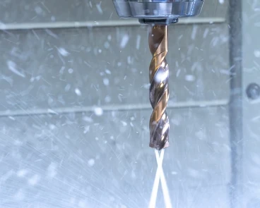
If the part repeats, the material is expensive, or the intersection is severe, involve the tool supplier early. Custom geometry can solve problems that feed reduction alone cannot. Possible changes include a stronger cutting-edge preparation, coating changes, a different carbide grade, coolant-hole adjustment, guide-pad changes on a gun drill, or a drill length and body design made for the actual hole sequence.
Custom tooling is not automatically the expensive option. A standard drill that breaks unpredictably, creates scrap, or forces a slow manual deburring step may cost more per accepted part than a tool designed around the intersection. The decision should be based on real numbers: tool life, cycle time, scrap risk, deburring time, inspection burden, and delivery pressure.
A practical troubleshooting sequence
When a cross-hole job starts causing trouble, avoid changing five things at once. Work through the process in a controlled way.
Problem seen on the part or tool | Likely cause | First corrective move |
Chipped cutting lips at break-through | Feed too high during unsupported cutting | Reduce feed through the intersecting zone and inspect edge prep |
Rough bore after the cross hole | Chips recutting or coolant not reaching the edge | Improve through-coolant flow, filtration, and chip flushing |
Oversize or shifted hole | Drill deflection, long overhang, off-center intersection | Shorten the drill, reduce overhang, improve guidance |
Heavy internal burr | Vibration, dull edge, aggressive exit feed | Use reduced exit feed and plan internal deburring if required |
Sudden torque rise | Chip packing in flute or cavity | Stop and inspect chip shape, coolant pressure, and evacuation path |
Work hardening or rubbing | Feed/speed reduced too far for the material | Restore enough chip load or change tool geometry/coating |
Cross-hole drilling is rarely solved by one magic parameter. It is a balance: slow down enough to protect the drill during the interruption, but keep enough cutting action to avoid rubbing. Use enough coolant to move chips, but confirm the chips have somewhere to go. Choose a rigid tool, but do not assume carbide stiffness can overcome poor support.

Conclusion
Cross holes are difficult because the drill is asked to cut without steady support. That is the core issue behind the noise, burrs, edge damage, chip packing, and hole drift. Once the problem is viewed that way, the fixes become more practical: reduce feed through the interrupted zone, keep coolant and chips under control, use the shortest rigid drill possible, and consider custom geometry when the part repeats or the intersection is severe.
For shops machining mold cooling channels, crankshaft oil passages, hydraulic blocks, and other intersecting-hole parts, the goal is not simply to get the drill through the hole once. The goal is a repeatable process that protects the tool, keeps the passage clean, and avoids hidden burrs that can cause trouble later.
HNCarbide works with carbide drilling and holemaking applications where tool geometry, coating, coolant delivery, and process stability all affect cost per part. If cross-hole drilling keeps damaging tools or slowing production, it is worth reviewing the full setup before assuming the part is the problem.




