
Carbide End Mill Structure and Its Role in Modern CNC Machining
Table of Contents
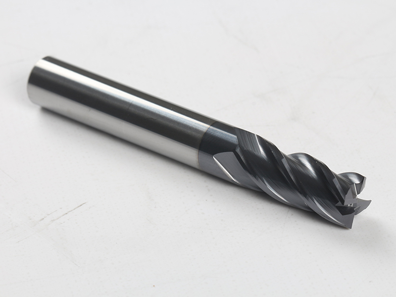
A carbide end mill looks simple on a tool cart: a round shank, a few spiral flutes, a sharp end, and often a colored coating. On the machine, it is anything but simple. The same cutter influences dimensional accuracy, surface finish, cycle time, spindle load, scrap risk, and tool cost per part. For a CNC shop, choosing the wrong end mill is rarely just a tooling mistake. It can show up as chatter in a pocket, burrs on a finished wall, unexpected tool breakage in stainless steel, or a quote that no longer makes money.
This guide explains the structure of solid carbide end mills and why they hold such an important position in modern CNC machining. The focus is practical: what the material grade, flute geometry, coating, machine setup, and cutting parameters mean when a production manager or machining engineer has to make a reliable choice.
Why Carbide End Mills Matter in CNC Production
End mills are used for side milling, slotting, pocketing, profiling, ramping, finishing, and 3D contouring. In many machining centers they are among the most frequently changed tools in the magazine. A solid carbide end mill combines high hardness, good hot strength, and precise ground geometry, which allows it to run faster than high speed steel in many industrial conditions.
That speed advantage matters because cycle time is often more expensive than the tool itself. A carbide cutter that costs several times more than an HSS cutter may still lower the cost per part if it holds size longer, removes material faster, and reduces tool changes. The tradeoff is that carbide is less forgiving. A loose holder, long overhang, weak workholding, poor chip evacuation, or a careless feed and speed change can chip the cutting edge quickly.
The Material Core: Tungsten Carbide and Cobalt Binder
The phrase solid carbide usually refers to cemented carbide, a sintered composite made mainly from tungsten carbide particles and a metallic cobalt binder. Tungsten carbide provides the hardness, wear resistance, and thermal stability. Cobalt binds the carbide grains together and adds toughness, helping the tool survive impact and vibration.
The balance between hardness and toughness is a design decision. Fine or submicron carbide grains can produce a sharper, more wear-resistant edge for finishing, hardened materials, and smaller-diameter tools. Higher cobalt content generally improves toughness for interrupted cuts, less rigid setups, and roughing, but too much binder can reduce hot hardness and wear resistance. Lower cobalt content can improve abrasion resistance, but the edge becomes less tolerant of shock.
This is why two end mills with the same diameter, flute count, and coating can behave differently. The carbide grade underneath the coating determines how much edge strength the tool has before geometry and coating even enter the conversation.
Geometry: Where Cutting Behavior Is Designed
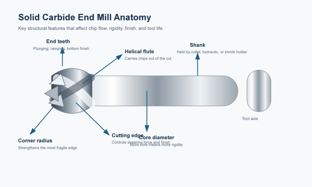
The geometry of a carbide end mill controls cutting force, chip formation, chip evacuation, heat flow, and tool stability. Shops often start with flute count because it is easy to see, but flute count is only one part of the system.
Flute Count and Chip Space
Two-flute end mills leave more room for chips. They are common in aluminum, plastics, and slotting operations where chips are long and need space to clear. Three-flute tools are often used as a bridge between chip clearance and edge strength, especially in aluminum and some mixed-material work. Four-flute and higher-flute tools increase core strength and allow higher feed rates in side milling, finishing, steel, stainless steel, and harder materials, but they leave less chip space.
A common shop-floor error is using too many flutes in a full-width slot. The tool may look stronger, but packed chips can drive heat into the edge, weld material to the flute, and break the cutter.
Helix Angle, Pitch, and Vibration Control
A lower helix angle generally gives a stronger edge and can help in harder or tougher materials. A higher helix angle shears more smoothly, reduces cutting force, and is often useful in aluminum and finishing operations. Variable helix and variable pitch designs disturb the regular vibration pattern created by repeated tooth engagement. In high-speed machining, that difference can turn an unstable process into a repeatable one.
End Style and Corner Protection
Square end mills create flat bottoms and sharp shoulders. Ball nose end mills are used for 3D contouring, molds, dies, and smooth sculpted surfaces. Corner radius end mills strengthen the most vulnerable part of the tool and are often preferred for roughing, hard materials, and aerospace-style pocketing where sharp corners are not required.
End mill feature | What it changes | Typical use |
2 flutes | More chip space, lower core strength | Aluminum, plastics, slotting, pocket roughing |
4+ flutes | Higher rigidity and feed capacity, less chip space | Steel, stainless steel, finishing, side milling |
High helix | Lower cutting force and smoother shearing | Aluminum, finishing, thin-wall work |
Variable helix/pitch | Reduces harmonic chatter | High-speed machining, long reach, unstable cuts |
Corner radius | Protects the corner from chipping | Roughing, hard materials, production milling |
How Carbide End Mills Are Made
Most solid carbide end mills begin as sintered carbide rods. The rod quality, grain uniformity, straightness, and internal defects all affect the finished tool. Multi-axis CNC tool grinders then use diamond wheels to form the flutes, gash, relief, rake, helix, and end geometry. Advanced geometries, such as variable helix, variable pitch, chip splitters, polished flutes, and complex corner radii, demand tighter grinding control and usually increase cost.
After grinding, many tools receive edge preparation and PVD coating. Edge prep matters because a perfectly sharp but fragile edge may chip immediately in steel, while an edge that is too honed can rub in aluminum or micro-machining. Good manufacturing is not only about making a tool sharp. It is about making the edge predictable.
Carbide End Mills vs. HSS End Mills
High speed steel still has a place. It is tougher, less expensive, and more forgiving in manual machines, low-speed equipment, or one-off jobs where tool cost matters more than cycle time. Carbide becomes the stronger choice when the machine has enough rigidity and spindle speed to use its hardness and heat resistance.
In production CNC work, the decision should be based on total machining cost, not purchase price. Faster cutting speeds, longer tool life, fewer offsets, and fewer tool changes can outweigh a higher tool price. In a low-rigidity setup, the opposite may be true: a brittle carbide tool can chip before it pays for itself.
Factor | Solid carbide end mill | HSS end mill |
Wear resistance | High; keeps edge longer in abrasive or hard materials | Lower; dulls faster under heat and abrasion |
Heat resistance | Strong at higher cutting speeds | Softens sooner at elevated temperature |
Toughness | Less forgiving under vibration or shock | More forgiving in unstable cuts |
Cost | Higher purchase price | Lower purchase price |
Best fit | Rigid CNC machines, production runs, hard or abrasive materials | Manual work, special forms, low-speed machines, small batches |
Matching the Tool to the Workpiece Material
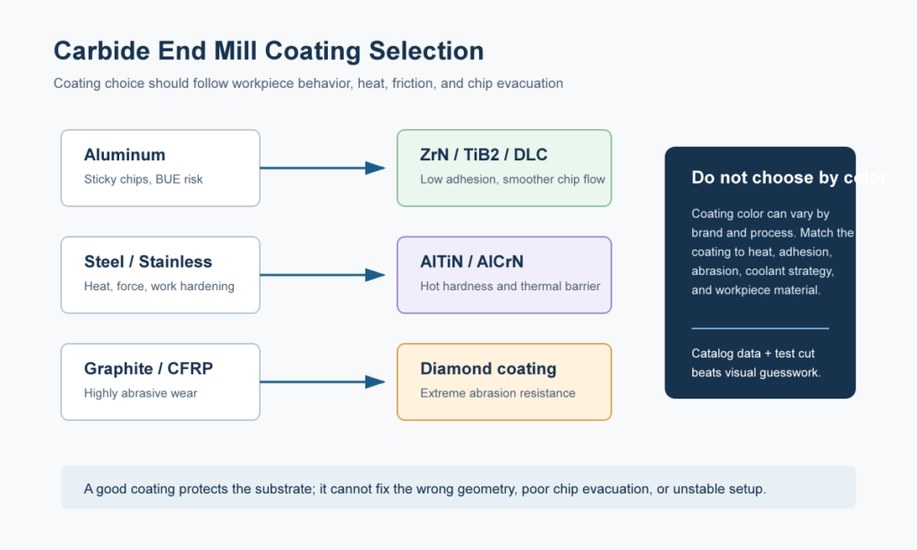
Material matching is where many tool failures begin. Aluminum wants sharp edges, polished flutes, high helix geometry, and coatings with low aluminum affinity, such as ZrN, TiB2, DLC, or sometimes no coating at all. Steel usually needs a stronger edge, enough flute count for productive feed rates, and heat-resistant coatings such as AlTiN or AlCrN. Stainless steel creates work-hardening and heat problems, so positive cutting action, stable engagement, coolant strategy, and chip evacuation are important. Titanium and nickel alloys require conservative engagement, strong cores, corner protection, and careful heat control.
Workpiece material | Tool selection focus | Common mistake to avoid |
Aluminum | 2-3 flutes, polished flutes, sharp rake, high helix, ZrN/TiB2/DLC or uncoated | Using a sticky high-temperature steel coating that encourages built-up edge |
Carbon and alloy steel | 4+ flutes, stronger core, corner radius, AlTiN or AlCrN | Running too slow and rubbing, or too aggressive in a weak holder |
Stainless steel | 3-5 flutes, variable geometry, sharp but supported edge, good coolant | Letting the tool dwell and work-harden the surface |
Titanium and nickel alloys | Strong core, corner radius, controlled engagement, high-performance coating | Overheating the edge with poor chip thinning or weak coolant strategy |
Graphite/composites | Abrasion-resistant grades or diamond coating when appropriate | Using a general steel tool and expecting normal wear life |
Coatings: Useful, but Not Magic
Coatings protect the carbide substrate by improving wear resistance, reducing friction, or acting as a thermal barrier. TiN is a basic general-purpose coating. TiCN can help with abrasive wear in some steels and cast iron. AlTiN and AlCrN are common in high-temperature steel, stainless, titanium, and dry or semi-dry machining. ZrN, TiB2, and DLC are often chosen for aluminum and non-ferrous materials because they reduce sticking. CVD diamond is used for graphite, ceramics, and abrasive composites, but it is not suitable for ferrous metals.
The coating must match the cut. A heat-resistant coating can perform well in dry steel milling because it pushes heat into the chip. The same coating may perform poorly in gummy aluminum if it increases built-up edge. Coating color is also not a reliable technical standard; manufacturers may tune color for branding.
Cutting Parameters: Start with Physics, Then Adjust for the Setup
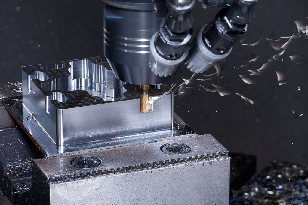
Cutting speed, spindle speed, chip load, feed rate, axial depth of cut, radial width of cut, coolant, and tool overhang all interact. The starting point should come from a manufacturer chart or a proven shop standard for the exact tool family and material.
The basic calculations are simple. RPM equals surface speed multiplied by 3.82, divided by cutter diameter in inches. Feed rate equals RPM multiplied by chip load per tooth and flute count. The harder part is deciding whether the machine, holder, workholding, and tool length can support the calculated value.
For example, a 1/2 in four-flute coated carbide end mill in 4140 steel might start around 350 SFM and 0.0028 in chip load per tooth, giving about 2,674 RPM and roughly 30 IPM. A long-reach holder, thin wall, or less rigid machine may require a reduction. A high-efficiency milling path with light radial engagement may allow higher feed due to chip thinning. The catalog number is only the beginning; the cut geometry decides the final parameter.
Troubleshooting Common Carbide End Mill Problems
When a carbide end mill fails, the visible damage often points to the process problem. A broken tool may come from excessive chip load, chip packing, long overhang, or a worn edge that was left in the cut too long. Chipped corners often point to vibration, interrupted impact, weak edge geometry, or a missing corner radius. Rapid flank wear can come from too much speed, too little feed, poor coating choice, or abrasive material. Chatter usually means the tool, holder, workpiece, or cutting parameters are exciting a vibration mode.
Problem | Likely cause | Practical correction |
Tool breakage | Chip packing, high feed, long overhang, worn tool | Improve chip evacuation, reduce load, shorten setup, replace tool earlier |
Edge chipping | Vibration, interrupted cut, weak edge, poor holder rigidity | Use stronger geometry, corner radius, better holder, adjusted speed/feed |
Fast wear | Excessive speed, rubbing, wrong coating, abrasive material | Reduce SFM, restore chip load, choose material-specific coating |
Chatter | Low rigidity or resonant parameters | Shorten overhang, change RPM, reduce radial/axial engagement, use variable pitch |
Poor finish | Worn tool, chatter, excessive feed, chip recutting | Replace tool, clear chips, tune feed, improve coolant or air blast |
Burrs | Dull edge, unsuitable geometry, wrong finishing pass | Use sharper finishing tool, change lead-in/out, add spring pass if needed |
The Strategic Role of Carbide End Mills in Modern CNC Shops
The importance of carbide end mills has grown as CNC machining has moved toward higher spindle speeds, tighter tolerances, smaller batch sizes, more difficult alloys, and more automated production. A modern machining center may run unattended or with limited operator intervention. In that environment, tool reliability is not a convenience. It protects the machine, the part, and the production schedule.
Carbide end mills also sit at the intersection of CAM strategy and shop economics. Adaptive clearing, trochoidal milling, peel milling, high-speed finishing, and 5-axis contouring all rely on stable tool engagement. The cutter must be selected together with the toolpath, holder, coolant plan, and inspection requirement. A low-cost general-purpose end mill may work well for a simple fixture plate. It may be the wrong choice for titanium pockets, medical components, mold finishing, or hardened die work.
What to Check Before Buying Carbide End Mills
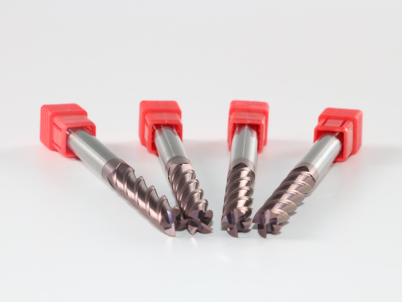
For tooling buyers and production managers, the best purchase is not always the tool with the longest specification sheet. Ask whether the supplier can recommend geometry by material, provide reliable starting parameters, maintain repeatable batches, support coating choices, and explain failure modes when a tool does not perform as expected. Consistency is especially important for repeat production. A tool that performs well once but changes behavior from batch to batch is hard to manage on a production floor.
A practical evaluation should include the workpiece material, hardness, operation type, tool diameter, flute length, reach, holder type, coolant strategy, machine rigidity, target finish, and expected tool life. Test in a controlled way, record the actual parameters, and compare cost per part rather than tool price alone.
Future Trends: Smarter Tools and More Specific Geometry
The next step for carbide end mills is not one single breakthrough. It is a steady move toward more application-specific substrates, nano-grain carbide, tougher high-temperature coatings, better edge preparation, and tool designs matched to modern CAM paths. Sensors and data-driven tool monitoring are also becoming more relevant in high-value manufacturing, where vibration, spindle load, and thermal patterns can help predict tool wear before a part is lost.
Additive manufacturing may influence some cutting tool designs, especially where internal coolant channels or hybrid structures create real performance advantages. For standard solid carbide end mills, precision grinding and coating technology will remain central, but the surrounding process data will become more important.

Conclusion
A carbide end mill is a small component in the CNC machining system, but it carries a large share of the process risk. Its material grade determines the hardness-toughness balance. Its geometry controls chip flow, force, vibration, and surface finish. Its coating changes wear and heat behavior. Its final performance depends on the machine, holder, coolant, toolpath, and operator discipline.
For shops machining steel, stainless steel, aluminum, titanium, molds, dies, or precision components, the best results come from treating carbide end mills as engineered tools rather than consumables. HNCarbide supports this approach with carbide cutting tools designed for practical production needs, helping CNC teams match tool structure to real machining conditions.




